2006 MERCEDES-BENZ SPRINTER boot
[x] Cancel search: bootPage 24 of 2305

3.7 USING THE DRBIIIT
Refer to the DRBIIItuser guide for instructions
and assistance with reading trouble codes, erasing
trouble codes, and other DRBIIItfunctions.
3.8 DRBIIITERROR MESSAGES
Under normal operation, the DRBIIItwill dis-
play one of only two error messages: user-requested
WARM Boot or User-Requested COLD Boot. If the
DRBIIItshould display any other error message,
record the entire display and call the STAR Center.
This is a sample of such an error message display:
ver: 2.14
date: 26 Jul93
file: key_iff.cc
date: Jul26 1993
line: 548
err: 0xi
User-Requested COLD Boot
Press MORE to switch between this display
and the application screen.
Press F4 when done noting information.
3.9 DRBIIITDOES NOT POWER UP
(BLANK SCREEN)
If the LED's do not light or no sound is emitted at
start up, check for loose cable connections or a bad
cable. Check the vehicle battery voltage (data link
connector cavity 16). A minimum of 11 volts is
required to adequately power the DRBIIIt. Check
for proper grounds at DLC cavities 4 and 5.
If all connections are proper between the
DRBIIItand the vehicle or other devices, and the
vehicle battery is fully charged, an inoperative
DRBIIItmay be the result or a faulty cable or
vehicle wiring.
3.10 DISPLAY IS NOT VISIBLE
Low temperatures will affect the visibility of the
display. Adjust the contrast to compensate for this
condition.
4.0 DISCLAIMERS, SAFETY,
WARNINGS
4.1 DISCLAIMERS
All information, illustrations, and specifications
contained in this manual are based on the latest
information available at the time of publication.
The right is reserved to make changes at any time
without notice.
4.2 SAFETY
4.2.1 TECHNICIAN SAFETY INFORMATION
WARNING: WHEN OPERATING, ENGINES
PRODUCE AN ODORLESS GAS CALLED
CARBON MONOXIDE. INHALING CARBON
MONOXIDE GAS CAN RESULT IN SLOWER
REACTION TIMES AND CAN LEAD TO
PERSONAL INJURY OR DEATH. WHEN THE
ENGINE IS OPERATING, KEEP SERVICE
AREAS WELL VENTILATED OR ATTACH THE
VEHICLE EXHAUST SYSTEM TO THE SHOP
EXHAUST REMOVAL SYSTEM.
Set the parking brake and block the wheel before
testing or repairing the vehicle. It is especially
important to block the wheels on front-wheel drive
vehicles; the parking brake does not hold drive
wheels.
When servicing a vehicle, always wear eye pro-
tection, and remove any metal jewelry such as
rings, watchbands or bracelets that might make an
inadvertent electrical contact.
When diagnosing a body system problem, it is
important to follow approved procedures where
applicable. These procedures can be found in this
11
GENERAL INFORMATION
Page 325 of 2305

read opposite switch states.Note: The BS and
BLS are in the same switch housing.
BRAKE LAMP SWITCH (BLS):This switch pre-
pares the CAB for a possible antilock event. The
CAB uses an output state voltage from the BLS
when the brake pedal is either depressed/released.
The Fused Ignition Switch Output circuit supplies
12 volts to the BLS. A depressed brake pedal will
close the BLS circuit and the BLS Output circuit
supplies 12 volts at the CAB. When the driver
releases the brake pedal, the BLS Output circuit
voltage drops to 0 volts and the CAB senses the
brake pedal state. This tells the CAB what position
the brake pedal is currently in to make an ABS
event possible. When using the DRBIIItin Inputs/
Outputs, the BS and BLS will read opposite switch
states.Note: The BS and BLS are in the same
switch housing.
TRACTION CONTROL SYSTEM SWITCH
(TCSS):This switch signals the CAB to either turn
ON or OFF the TCS. The driver can toggle the
TCSS, which receives 12 volts from the D (+) Relay
Output circuit. Depending on the position of the
TCSS, open or closed, the CAB receives the TCSS
state voltage on the TCS Switch Sense circuit.
When 12 volts are applied to the TCS Switch Sense
circuit, the TCS is OFF. When no voltage is present,
the TCS is ON.
WHEEL SPEED SENSORS AND TONE
WHEELS:The Bosch 5.7 system uses one passive
WSS on each wheel. The sensor measures the wheel
speed by monitoring a rotating tone wheel. As the
teeth of the tone wheel move through the magnetic
field of the sensor an AC voltage and amperage is
generated. This signal frequency increases or de-
creases proportionally to the speed of the wheel.
The CAB monitors this signal to check for a sudden
change in single or multiple wheel decelerations. If
the deceleration of one or more wheels is not within
a predetermined amount, the CAB takes control for
antilock action through the HCU. Each WSS has a
magnetic inductive pick up coil (WSS) that is
mounted to a fixed component. There is an air gap
between the tone wheel and the speed sensor as-
sembly. Diagnostically, the coils of the Wheel Speed
Sensors have the same amount of resistance. When
measured across the CAB harness connector termi-
nals, the resistance should be between 1100 - 1800
ohms. Refer to service manual for WSS replacement
and air gap specifications.
Correct ABS operation is dependent on Tone
Wheel speed signal from the WSS. The vehicle
wheels and tires should all be the same size and
type to get accurate signals. In addition, all tires
should be at recommended tire pressures.3.7.5 SELF TESTS
The system software includes several self tests
that are performed every time the ignition is turned
on and the vehicle is driven. Some of the self tests
occur immediately, while others occur under normal
driving conditions while not in antilock operation.
The CAB checks continuously for a missing or
erratic WSS signals/circuits, tone wheels, solenoids,
pump motor or solenoid relay by performing several
tests such as: dynamic, static, ohmic, voltage drop,
and timed response. If any component exhibits a
fault during testing, the CAB will request to illumi-
nate the ABS and TCS warning indicators.
As an additional check of the ESP system, a road
test procedure is available on the DRBIIIt. This
test should be carried out when any ESP component
is replaced in order to ensure proper function. Since
the wheel speed sensors are required inputs to the
ESP, this test should also be performed if the wheel
speed sensors are replaced.
First, the brakes are applied with the vehicle
stationary. Then, the vehicle is driven at approxi-
mately 6 MPH. The driver has to make left and
right turns, with a minimum 90 degree steering
turning angle. If the indicator lamp goes out, every-
thing is in order. If the lamp remains illuminated,
the DRBIIItwill display the fault codes that are
causing the test to fail. The road test function is set
in the ESP control module, and can only be deacti-
vated once there are no more fault codes detected.
The Steering Angle Sensor must be initialized. A
procedure is carried out using the DRBIIItto
ensure that the module detects the exact position of
the sensor. The sensor must be calibrated any time
wheel alignment is changed, the steering column is
removed and re-installed, or the sensor is replaced.
3.8 USING THE DRBIIIT
Refer to the DRBIIItuser 's guide for instructions
and assistance with reading diagnostic trouble
codes, erasing diagnostic trouble codes and other
DRBIIItfunctions.
3.9 DRBIIITERROR MESSAGES
Under normal operation, the DRBIIItwill dis-
play one of only two error messages:
Ð User-Requested WARM Boot or User-Requested
COLD Boot.
If the DRBIIItshould display any other error
message, record the entire display and call the
STAR Center for information and assistance. This
is a sample of such an error message display:
4
GENERAL INFORMATION
Page 326 of 2305

ver: 2.14
date: 26 Jul93
file: key_iff.cc
date: Jul 26 1993
line: 548
err: 0x1
User-Requested COLD Boot
Press MORE to switch between this display
and the application screen.
Press F4 when done noting information.
3.9.1 DRBIIITDOES NOT POWER UP
(BLANK SCREEN)
If the LED's do not light or no sound is emitted at
start up, check for loose cable connections or a bad
cable. Check the vehicle battery voltage (data link
16-way connector cavity 16). A minimum of 11 volts
is required to adequately power the DRBIIIt. Also
check for a good ground at DLC.
If all connections are proper between the
DRBIIItand the vehicle or other devices, and the
vehicle battery is fully charged, an inoperative
DRBIIItmay be the result or a faulty cable or
vehicle wiring.
3.9.2 DISPLAY IS NOT VISIBLE
Low temperatures will affect the visibility of the
display. Adjust the contrast to compensate for this
condition.
4.0 DISCLAIMERS, SAFETY,
WARNINGS
4.1 DISCLAIMERS
All information, illustrations, and specifications
contained in this manual are based on the latestinformation available at the time of publication.
The right is reserved to make changes at any time
without notice.
4.2 SAFETY
4.2.1 TECHNICIAN SAFETY INFORMATION
WARNING: ENGINES PRODUCE CARBON
MONOXIDE THAT IS ODORLESS, CAUSES
SLOWER REACTION TIME, AND CAN LEAD
TO SERIOUS INJURY. WHEN THE ENGINE IS
OPERATING, KEEP SERVICE AREAS WELL
VENTILATED OR ATTACH THE VEHICLE
EXHAUST SYSTEM TO THE SHOP EXHAUST
REMOVAL SYSTEM.
Set the parking brake and block the wheels before
testing or repairing the vehicle. It is especially
important to block the wheels on front-wheel drive
vehicles; the parking brake does not hold the front
drive wheels.
When servicing a vehicle, always wear eye pro-
tection, and remove any metal jewelry such as
watchbands or bracelets that might make an inad-
vertent electrical contact.
When diagnosing an antilock brake or adjustable
pedals system problem, it is important to follow
approved procedures where applicable. These pro-
cedures can be found in the service manual. Follow-
ing these procedures is very important to safety of
individuals performing diagnostic tests.
4.2.2 VEHICLE PREPARATION FOR
TESTING
Make sure the vehicle being tested has a fully
charged battery. If it does not, false diagnostic codes
or error messages may occur.
4.2.3 SERVICING SUB-ASSEMBLIES
Some components of the antilock brake and trac-
tion control are intended to be serviced in assembly
only. Attempting to remove or repair certain sub-
components may result in personal injury and/or
improper system operation. Only those components
with approved repair and installation procedures in
the service manual should be serviced.
5
GENERAL INFORMATION
Page 724 of 2305

SCOPE OF WORK FOR MAINTENANCE SERVICE
Oil Service
²Engine: Oil change and filter replacement
Check fluid levels of the following system, refill as neces-
sary.
²If fluid is lost, trace and eliminate cause - as a
separate order.
²Power-assisted steering
Lubrication work:
²Trailer tow hitch (original equipment)
Maintenance
²ASSYST maintenance computer reset
Function check
²Signalling system, warning and indicator lamps
²Headlamps, exterior lighting
²Windshield wipers, windshield washer system
Check for leaks and damage
²Check for abrasion points and ensure that lines
are correctly routed!
²All lines and hoses, sensor cables
²Rubber boots on front axle drive shafts, rubber
boots on front axle suspension ball joints, shock
absorbers
²Check fluid levels for the following systems, cor-
rect as necessary
NOTE: Should there be a loss of fluid which cannot
be explained by regular use, trace and eliminate the
cause.
²Engine cooling system. Check corrosion inhibi-
tor/antifreeze, refill as necessary.
²Hydraulic brake system
²Battery
²Windshield washer system
Engine
²Fuel filter renewal - Every oil service
²Air cleaner with maintenance indicator:
²Check degree of contamination.
²Air cleaner filter element renewed as necessary.
Chassis and body
²Trailer coupling: Check operation, play and
retaining fixtures
²Secondary rubber springs: Visual check
²Tire pressures: Correct as necessary, including
spare tire
²Check thickness of brake pads
²Brake test
²Check condition of steering mechanism
²Heating/ventilation dust filter renewal
ADDITIONAL MAINTENANCE WORK
Automatic transmission once only at 80,000 miles / 128000
km
²Oil and filter change
During every second maintenance service
²Air cleaner without maintenance indicator:
²Air cleaner filter element renewal
²Check poly-V-belt for wear and signs of damage
During every fourth maintenance service
²Change rear axle fluid
ADDITIONAL MAINTENANCE WORK AFTER YEARS
Every 2 years
²Change brake fluid.
Every 3 years
²Air cleaner filter element renewal (note installa-
tion date)
Every 15 years or 100,000 miles
²Coolant renewal
²Note coolant composition
INTERNATIONAL SYMBOLS
DESCRIPTION
DaimlerChrysler Corporation uses international
symbols to identify engine compartment lubricant
and fluid inspection and fill locations (Fig. 3).
Fig. 3 INTERNATIONAL SYMBOLS
VALUBRICATION & MAINTENANCE 0 - 9
Page 752 of 2305

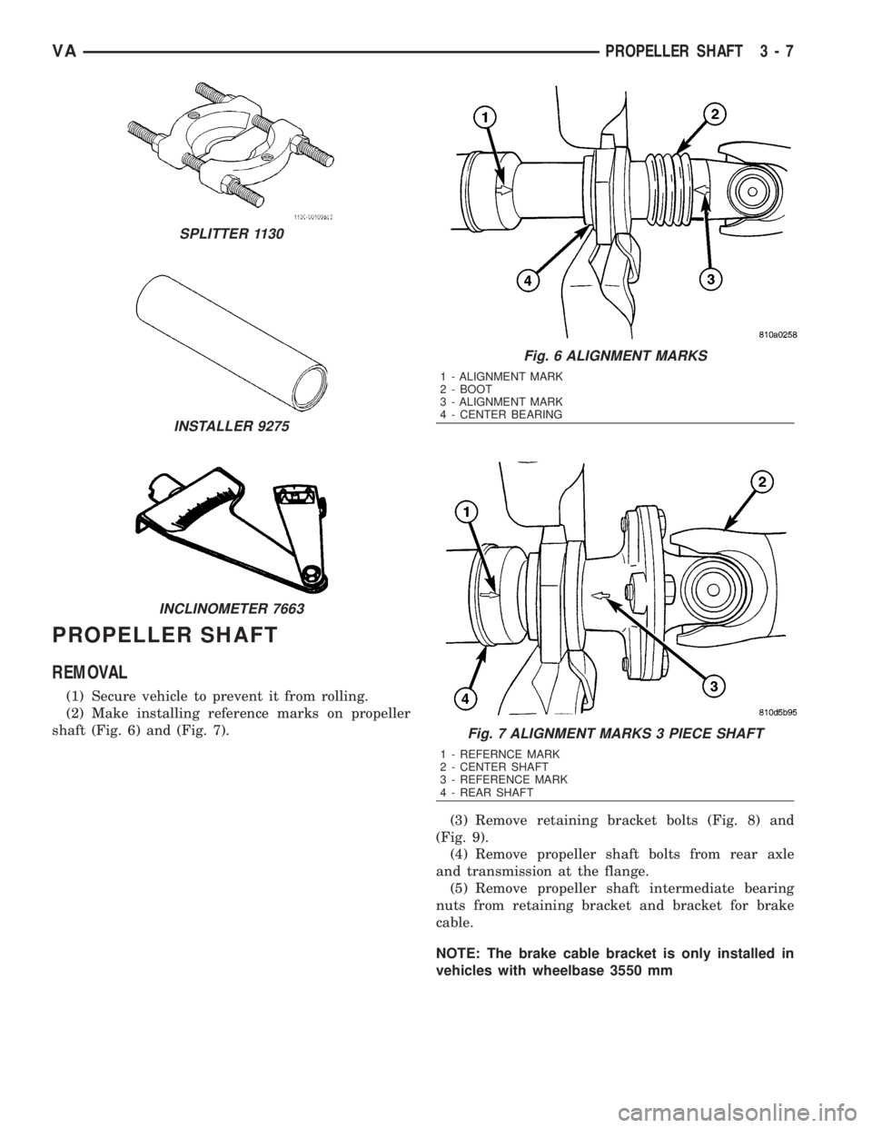
PROPELLER SHAFT
REMOVAL
(1) Secure vehicle to prevent it from rolling.
(2) Make installing reference marks on propeller
shaft (Fig. 6) and (Fig. 7).
(3) Remove retaining bracket bolts (Fig. 8) and
(Fig. 9).
(4) Remove propeller shaft bolts from rear axle
and transmission at the flange.
(5) Remove propeller shaft intermediate bearing
nuts from retaining bracket and bracket for brake
cable.
NOTE: The brake cable bracket is only installed in
vehicles with wheelbase 3550 mm
SPLITTER 1130
INSTALLER 9275
INCLINOMETER 7663
Fig. 6 ALIGNMENT MARKS
1 - ALIGNMENT MARK
2 - BOOT
3 - ALIGNMENT MARK
4 - CENTER BEARING
Fig. 7 ALIGNMENT MARKS 3 PIECE SHAFT
1 - REFERNCE MARK
2 - CENTER SHAFT
3 - REFERENCE MARK
4 - REAR SHAFT
VAPROPELLER SHAFT 3 - 7
Page 754 of 2305

(6) Remove shaft from the vehicle.
INSTALLATION
(1) Install propeller shaft intermediate bearing/
bearings to support and tighten nuts to 105 N´m (77
ft. lbs.).
(2) Install propeller shaft intermediate bearing
support/supports to frame floor and tighten bolts to
95 N´m (70 ft. lbs.).
(3) Install propeller shaft intermediate bearing
with retaining bracket and bracket for brake cable.
NOTE: The bracket is only installed on vehicles
with wheelbase 3550 mm.
(4) Install propeller shaft to rear axle and trans-
mission flange with installation marks are aligned.
Tighten bolts to 70 N´m (66 ft. lbs.).
(5) Install retaining bracket and tighten bolts to
100 N´m (74 ft. lbs.).
CENTER BEARING
REMOVAL
(1) Remove propeller shaft.
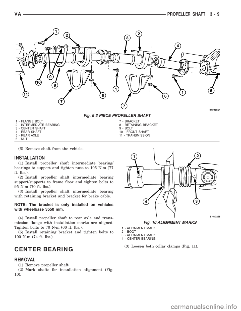
(2) Mark shafts for installation alignment (Fig.
10).(3) Loosen both collar clamps (Fig. 11).
Fig. 9 3 PIECE PROPELLER SHAFT
1 - FLANGE BOLT 7 - BRACKET
2 - INTERMEDIATE BEARING 8 - RETAINING BRACKET
3 - CENTER SHAFT 9 - BOLT
4 - REAR SHAFT 10 - FRONT SHAFT
5 - REAR AXLE 11 - TRANSMISSION
6 - NUT
Fig. 10 ALIGNMENT MARKS
1 - ALIGNMENT MARK
2 - BOOT
3 - ALIGNMENT MARK
4 - CENTER BEARING
VAPROPELLER SHAFT 3 - 9
Page 755 of 2305

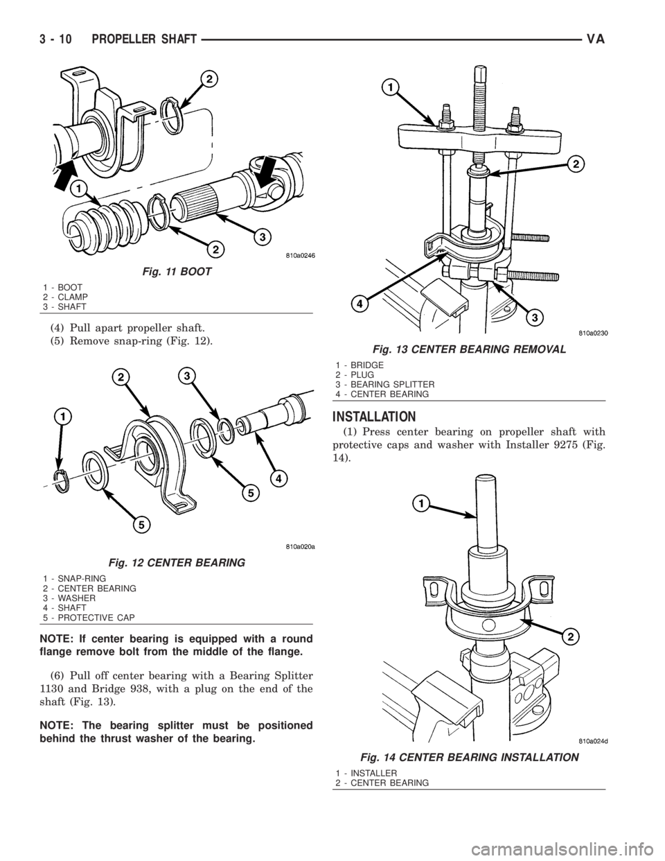
(4) Pull apart propeller shaft.
(5) Remove snap-ring (Fig. 12).
NOTE: If center bearing is equipped with a round
flange remove bolt from the middle of the flange.
(6) Pull off center bearing with a Bearing Splitter
1130 and Bridge 938, with a plug on the end of the
shaft (Fig. 13).
NOTE: The bearing splitter must be positioned
behind the thrust washer of the bearing.
INSTALLATION
(1) Press center bearing on propeller shaft with
protective caps and washer with Installer 9275 (Fig.
14).
Fig. 11 BOOT
1 - BOOT
2 - CLAMP
3 - SHAFT
Fig. 12 CENTER BEARING
1 - SNAP-RING
2 - CENTER BEARING
3 - WASHER
4 - SHAFT
5 - PROTECTIVE CAP
Fig. 13 CENTER BEARING REMOVAL
1 - BRIDGE
2 - PLUG
3 - BEARING SPLITTER
4 - CENTER BEARING
Fig. 14 CENTER BEARING INSTALLATION
1 - INSTALLER
2 - CENTER BEARING
3 - 10 PROPELLER SHAFTVA
Page 756 of 2305

NOTE: If center bearing is equipped with a round
flange install new bolt in middle of the flange and
tighten to 95 N´m (70 ft. bls.).
(2) Install snap-ring.
(3) Coat propeller shaft spline with universal
grease.
(4) Push rubber boot onto propeller shaft.
(5) Push together propeller shaft. Pay attention to
alignment markings for installation position.
(6) Ensure rubber seal is correctly installed and
attachnewcollar clamps.
(7) Install propeller shaft.
VAPROPELLER SHAFT 3 - 11