2006 MERCEDES-BENZ SPRINTER boot
[x] Cancel search: bootPage 1738 of 2305
LINKAGE
TABLE OF CONTENTS
page page
LINKAGE
DIAGNOSIS AND TESTING - OUTER TIE ROD
END ................................9
SPECIFICATIONS - TORQUE CHART.........9
SPECIAL TOOLS
FRONT SUSPENSION..................10TIE ROD END
REMOVAL.............................10
INSTALLATION.........................10
LINKAGE
DIAGNOSIS AND TESTING - OUTER TIE ROD
END
NOTE: If the outer tie rod end is equipped with a
lubrication fitting, grease the joint then road test
the vehicle before performing test.
(1) Raise the front of the vehicle. Place safety floor
stands under both lower control arms as far outboard
as possible. Lower the vehicle to allow the stands to
support some or all of the vehicle weight.
(2) Remove the front tires.
(3) Mount a dial indicator solidly to the vehicle
steering knuckle and then zero the dial indicator.(4) Position indicator plunger on the topside of the
outer tie rod end.
NOTE: The dial indicator plunger must be perpen-
dicular to the machined surface of the outer tie rod
end.
(5) Position a pry bar in order to pry downwards
on the outer tie rod end.
(6) If the travel exceeds 0.5 mm (0.020 in.), replace
the outer tie rod end (Refer to 19 - STEERING/
LINKAGE/TIE ROD END - REMOVAL).
(7) If the outer tie rod end is within specs reinstall
the front tires (Refer to 22 - TIRES/WHEELS/
WHEELS - STANDARD PROCEDURE).
SPECIFICATIONS - TORQUE CHART
TORQUE SPECIFICATIONS
DESCRIPTION N´m Ft. Lbs. In. Lbs.
Outer Tie Rod End Nut 130 96 Ð
Outer Tie Rod End Lock-
ing Nut50 37 Ð
Steering Gear Boot
Clamp7Ð62
VALINKAGE 19 - 9
Page 1957 of 2305
(3) Install bracket onto check and install bracket
bolt/nut.
(4) Tighten bracket bolt/nut to 6 N´m (53 in. lbs.).
(5) Install check bracket onto a-pillar.
(6) Apply Loctitet243 sealant check strap bolts
and install bolts.
(7) Tighten the M8 bolts to 35 N´m (26 ft. lbs.) or
tighten the M6 bolts to 10 N´m (89 in. lbs.).
(8) Install trim panel. (Refer to 23 - BODY/DOOR -
FRONT/TRIM PANEL - INSTALLATION)
(9) Connect battery negative cable.
DOOR
REMOVAL
(1) Disconnect and isolate battery negative cable.
(2) Remove mirror. (Refer to 23 - BODY/EXTERI-
OR/SIDE VIEW MIRROR - REMOVAL)
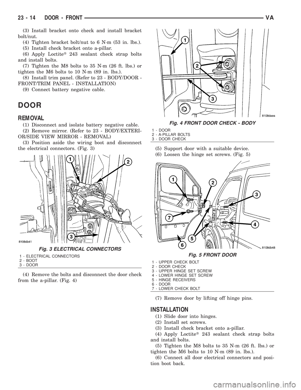
(3) Position aside the wiring boot and disconnect
the electrical connectors. (Fig. 3)
(4) Remove the bolts and disconnect the door check
from the a-pillar. (Fig. 4)(5) Support door with a suitable device.
(6) Loosen the hinge set screws. (Fig. 5)
(7) Remove door by lifting off hinge pins.
INSTALLATION
(1) Slide door into hinges.
(2) Install set screws.
(3) Install check bracket onto a-pillar.
(4) Apply Loctitet243 sealant check strap bolts
and install bolts.
(5) Tighten the M8 bolts to 35 N´m (26 ft. lbs.) or
tighten the M6 bolts to 10 N´m (89 in. lbs.).
(6) Connect all door electrical connectors and posi-
tion boot back.
Fig. 3 ELECTRICAL CONNECTORS
1 - ELECTRICAL CONNECTORS
2 - BOOT
3 - DOOR
Fig. 4 FRONT DOOR CHECK - BODY
1 - DOOR
2 - A-PILLAR BOLTS
3 - DOOR CHECK
Fig. 5 FRONT DOOR
1 - UPPER CHECK BOLT
2 - DOOR CHECK
3 - UPPER HINGE SET SCREW
4 - LOWER HINGE SET SCREW
5 - HINGE RECEIVERS
6 - DOOR
7 - LOWER CHECK BOLT
23 - 14 DOOR - FRONTVA
Page 1992 of 2305
RADIATOR CROSSMEMBER
REMOVAL
(1) Remove grille. (Refer to 23 - BODY/EXTERI-
OR/GRILLE - REMOVAL)
(2) Remove headlamps. (Refer to 8 - ELECTRI-
CAL/LAMPS/LIGHTING - EXTERIOR/FRONT
LAMP UNIT - REMOVAL)
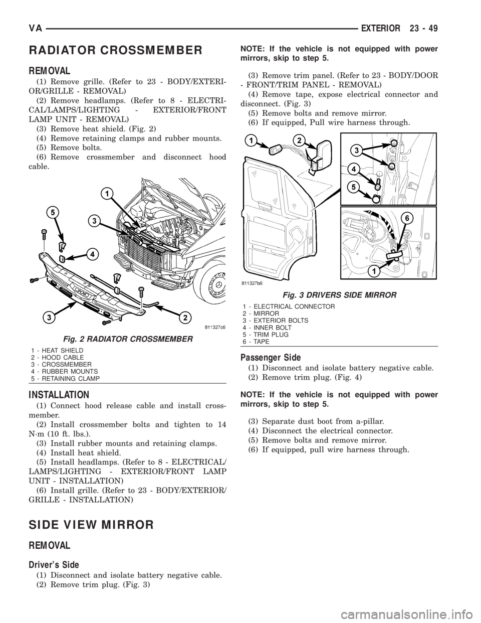
(3) Remove heat shield. (Fig. 2)
(4) Remove retaining clamps and rubber mounts.
(5) Remove bolts.
(6) Remove crossmember and disconnect hood
cable.
INSTALLATION
(1) Connect hood release cable and install cross-
member.
(2) Install crossmember bolts and tighten to 14
N´m (10 ft. lbs.).
(3) Install rubber mounts and retaining clamps.
(4) Install heat shield.
(5) Install headlamps. (Refer to 8 - ELECTRICAL/
LAMPS/LIGHTING - EXTERIOR/FRONT LAMP
UNIT - INSTALLATION)
(6) Install grille. (Refer to 23 - BODY/EXTERIOR/
GRILLE - INSTALLATION)
SIDE VIEW MIRROR
REMOVAL
Driver's Side
(1) Disconnect and isolate battery negative cable.
(2) Remove trim plug. (Fig. 3)NOTE: If the vehicle is not equipped with power
mirrors, skip to step 5.
(3) Remove trim panel. (Refer to 23 - BODY/DOOR
- FRONT/TRIM PANEL - REMOVAL)
(4) Remove tape, expose electrical connector and
disconnect. (Fig. 3)
(5) Remove bolts and remove mirror.
(6) If equipped, Pull wire harness through.
Passenger Side
(1) Disconnect and isolate battery negative cable.
(2) Remove trim plug. (Fig. 4)
NOTE: If the vehicle is not equipped with power
mirrors, skip to step 5.
(3) Separate dust boot from a-pillar.
(4) Disconnect the electrical connector.
(5) Remove bolts and remove mirror.
(6) If equipped, pull wire harness through.
Fig. 2 RADIATOR CROSSMEMBER
1 - HEAT SHIELD
2 - HOOD CABLE
3 - CROSSMEMBER
4 - RUBBER MOUNTS
5 - RETAINING CLAMP
Fig. 3 DRIVERS SIDE MIRROR
1 - ELECTRICAL CONNECTOR
2 - MIRROR
3 - EXTERIOR BOLTS
4 - INNER BOLT
5 - TRIM PLUG
6 - TAPE
VAEXTERIOR 23 - 49
Page 1993 of 2305
INSTALLATION
Driver's Side
(1) If equipped, pull wire harness through door.
(2) Install mirror and bolts.
(3) Tighten the bolts to 25 N´m (18 ft. lbs.).
NOTE: If vehicle is not equipped with power mir-
rors, skip to step 6.
(4) Connect electrical connector and replace tape.
(5) Install trim panel. (Refer to 23 - BODY/DOOR -
FRONT/TRIM PANEL - INSTALLATION)
(6) Install trim plug.
(7) Connect battery negative cable.
Passenger Side
(1) If equipped, pull wire harness through door.
(2) Install mirror and bolts.
(3) Tighten the bolts to 25 N´m (18 ft. lbs.).
NOTE: If vehicle is not equipped with power mir-
rors, skip to step 6.
(4) Connect the electrical connector.
(5) Connect dust boot to a-pillar.
(6) Install trim plug.
(7) Connect battery negative cable.
SIDE VIEW MIRROR - GLASS
REMOVAL
(1) Disconnect and isolate battery negative cable.
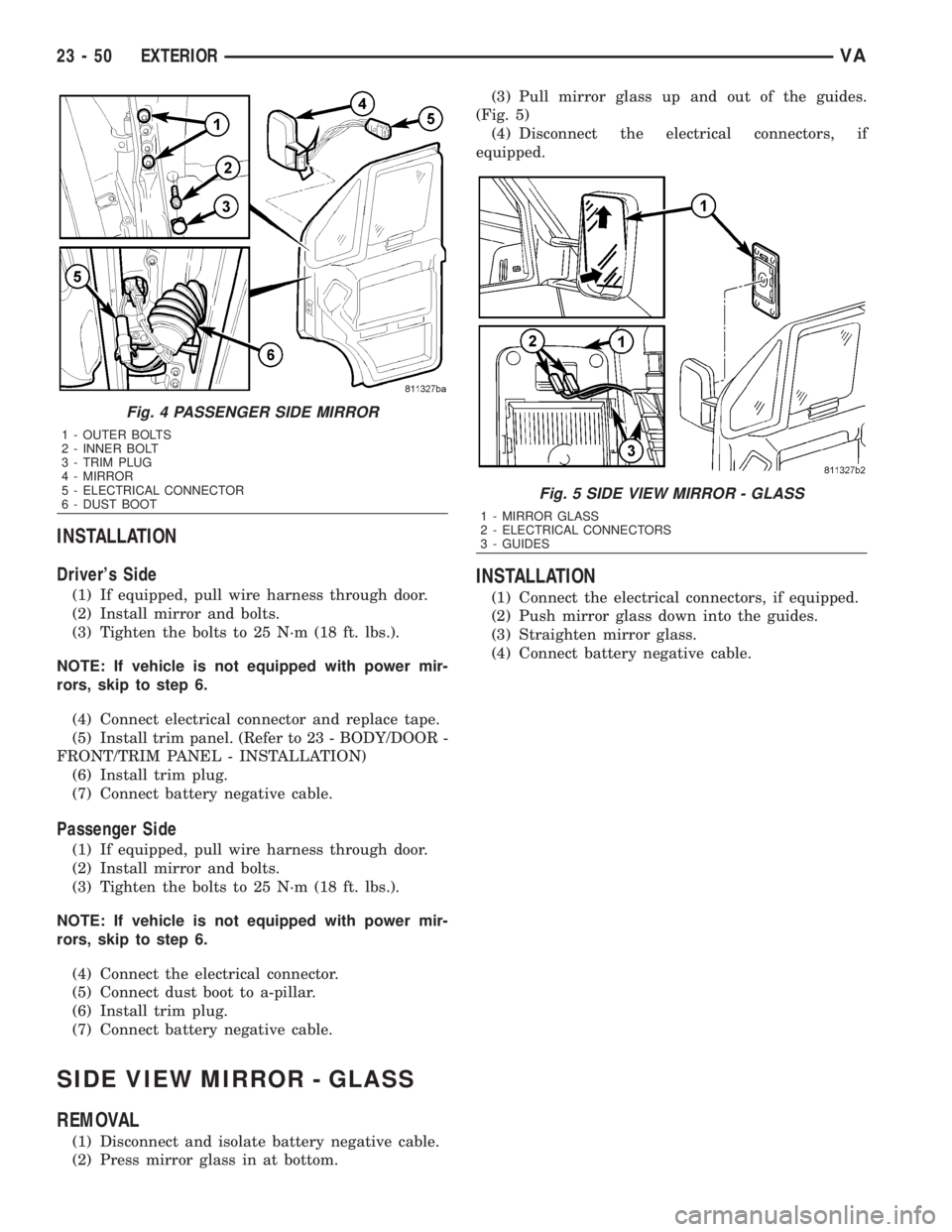
(2) Press mirror glass in at bottom.(3) Pull mirror glass up and out of the guides.
(Fig. 5)
(4) Disconnect the electrical connectors, if
equipped.
INSTALLATION
(1) Connect the electrical connectors, if equipped.
(2) Push mirror glass down into the guides.
(3) Straighten mirror glass.
(4) Connect battery negative cable.
Fig. 4 PASSENGER SIDE MIRROR
1 - OUTER BOLTS
2 - INNER BOLT
3 - TRIM PLUG
4 - MIRROR
5 - ELECTRICAL CONNECTOR
6 - DUST BOOT
Fig. 5 SIDE VIEW MIRROR - GLASS
1 - MIRROR GLASS
2 - ELECTRICAL CONNECTORS
3 - GUIDES
23 - 50 EXTERIORVA
Page 2170 of 2305
Emergency running function
If DTCs occur, safe-driving conditions must be re-
tained but full functionality of the transmission will
be limited to avoid damaging the automatic trans-
mission. In the event of certain DTCs the TCM
switches to emergency running. The TCM will store
the appropriate DTC codes and solenoids will be
de-energized (turned off)
The transmission effects will be:
²The last gear shifted remains in that position
²The modulating pressure and shift pressure in-
crease to maximum value
²The torque converter clutch is disengaged
(turned off)
Shifting manually after a DTC detection
NOTE: The vehicle can still be shifted
manually to 2nd or reverse gear.
To accomplish these shifts you must
Stop the vehicle
Turn the ignition off
Start the engine
Place the selector lever into D for 2nd gear
Place the selector lever into R for reverse gear
The emergency running function is retained until
the DTC is eliminated or the stored DTC code is
erased.
Stored (Intermittent) DTCs can be reset by cy-
cling the ignition switch
3.3.3 TROUBLE CODE ERASURE
Diagnostic Trouble Codes can be erased in two
ways. The first is to erase the DTC with the DRBIII
or scan tool. The second is if the DTC is no longer
present, the DTC is reset by the TCM (after an
ignition cycle), which will place the DTC in an
intermittent status (Stored DTC).
When there are no diagnostic trouble codes
stored in memory, the DRBIIItwill display
(NO DTC's DETECTED(
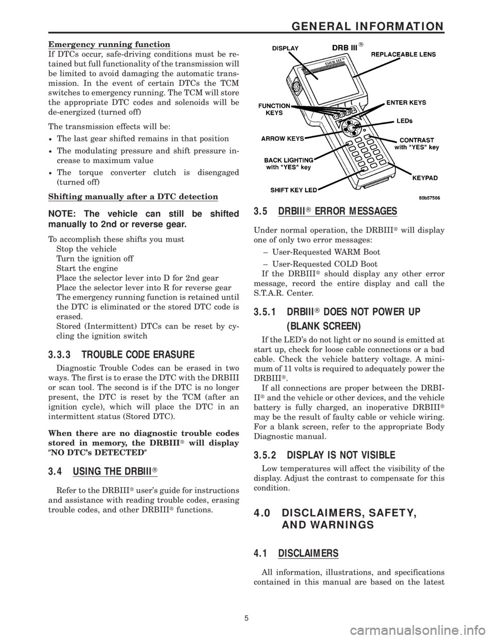
3.4 USING THE DRBIIIT
Refer to the DRBIIItuser's guide for instructions
and assistance with reading trouble codes, erasing
trouble codes, and other DRBIIItfunctions.
3.5 DRBIIITERROR MESSAGES
Under normal operation, the DRBIIItwill display
one of only two error messages:
± User-Requested WARM Boot
± User-Requested COLD Boot
If the DRBIIItshould display any other error
message, record the entire display and call the
S.T.A.R. Center.
3.5.1 DRBIIITDOES NOT POWER UP
(BLANK SCREEN)
If the LED's do not light or no sound is emitted at
start up, check for loose cable connections or a bad
cable. Check the vehicle battery voltage. A mini-
mum of 11 volts is required to adequately power the
DRBIIIt.
If all connections are proper between the DRBI-
IItand the vehicle or other devices, and the vehicle
battery is fully charged, an inoperative DRBIIIt
may be the result of faulty cable or vehicle wiring.
For a blank screen, refer to the appropriate Body
Diagnostic manual.
3.5.2 DISPLAY IS NOT VISIBLE
Low temperatures will affect the visibility of the
display. Adjust the contrast to compensate for this
condition.
4.0 DISCLAIMERS, SAFETY,
AND WARNINGS
4.1 DISCLAIMERS
All information, illustrations, and specifications
contained in this manual are based on the latest
5
GENERAL INFORMATION