2006 MERCEDES-BENZ SPRINTER manual transmission
[x] Cancel search: manual transmissionPage 17 of 2305

loads are connected to cables and mounted in a
storage case. The cables can be directly connected to
some airbag system connectors. Jumpers are used
to convert the load tool cable connectors to the other
airbag system connectors. The adapters are con-
nected to the module harness connector to open
shorting clips and protect the connector terminal
during testing. When using the load tool follow all of
the safety procedures in the service information for
disconnecting airbag system components. Inspect
the wiring, connector and terminals for damage or
misalignment. Substitute the airbag load tool in
place of a Driver or Passenger Airbag, seat belt
tensioner, clockspring (use a jumper if needed).
Then follow all of the safety procedures in the
service information for connecting airbag system
components. Read the module active DTCs. If the
module reports NO ACTIVE DTCs the defective
components has been removed from the system and
should be replaced. If the DTC is still active, con-
tinue this process until all components in the circuit
have been tested. Then disconnect the module con-
nector and connect the matching adapter to the
module connector. With all airbags disconnected
and the adapter installed the squib wiring can be
tested for open and shorted conditions.
3.1.6 DIAGNOSTIC TROUBLE CODES
Airbag diagnostic trouble codes consist of active
and stored codes. If more than one code exists,
diagnostic priority should be given to the active
codes. Each diagnostic trouble code is diagnosed by
following a specific testing procedure. The diagnos-
tic test procedures contain step-by-step instructions
for determining the cause of the trouble codes. It is
not necessary to perform all of the tests in this book
to diagnose an individual code. Always begin by
reading the diagnostic trouble codes with the
DRBIIIt. This will direct you to the specific test(s)
that must be performed. In certain test procedures
within this manual, diagnostic trouble codes are
used as a diagnostic tool.
3.1.6.1 ACTIVE CODES
If the lamp remains on, there could be an active
DTC in the system. The code becomes active as soon
as the malfunction is detected or key-on, whichever
occurs first. An active trouble code indicates an
on-going malfunction. This means that the defect is
currently there every time the airbag control mod-
ule checks that circuit or component. Some DTCs,
Internal Module and squib DTCs, will keep the
indicator illuminated even if they are no longer
active. If the lamp is on and no active codes are
present, cycling the ignition switch off and then on
will refresh the lamp state. It is impossible to erase
an active code.
3.1.6.2 STORED CODES
Airbag codes are automatically stored in the
ACM's memory as soon as the malfunction is de-
tected. A stored code indicates there was an active
code present at some time. Stored diagnostic trou-
ble code will remain stored until erased by the DRB.
If a malfunction is not active while performing a
diagnostic test procedure, the active code diagnostic
test will not locate the source of the problem. In this
case, the stored code can indicate an area to inspect.
Maintain a safe distance from all airbags while
performing the following inspection. If no obvious
problems are found, erase stored codes, and with
the ignition on wiggle the wire harness and connec-
tors, rotate the steering wheel from stop to stop.
Recheck for codes periodically as you work through
the system. This procedure may uncover a malfunc-
tion that is difficult to locate.
3.2 COMMUNICATION
3.2.1 COMMUNICATION K-LINES
The K-Lines are a group of circuits that connect
each control module to the Data Link Connector
(DLC). Each control module is connected to the DLC
with a single K-Line. The DRBIIItuses the K-Line
to communicate with each control module. With the
use of the K-Lines the DRBIIItis able to read each
control modules DTCs, sensor displays, I/Os etc. If
DRBIIItcommunications with a particular control
module is lost, one of the possible causes could be a
fault in the module's K-Line.
NOTE: It is important to note the DRBIIIT
uses the K-Lines for diagnostic and
monitoring functions and is no way
connected to the CAN data bus network.
The following modules that use the K-line on this
vehicle are:
²Airbag Control Module (ACM)
²Automatic Temperature Control (ATC)
²Cabin Heater Module (CHM)
²Central Timer Module (CTM)
²Controller Antilock Brake (CAB)
²Engine Control Module (ECM)
²Heater Booster Module (HBM)
²Instrument Cluster (IC)
²Shifter Assembly (SA)
²Security System Module (SSM)
²Sentry Key Remote Entry Module (SKREEM)
²Transmission Control Module (TCM)
4
GENERAL INFORMATION
Page 316 of 2305

DIAGNOSTIC TEST PROCEDURES — TELL US!
DaimlerChrysler Corporation is constantly working to provide the technician the best diagnostic manuals possible.
Your comments and recommendations regarding the diagnostic manuals and procedures are appreciated.
To best understand your suggestion, please complete the form giving us as much detail as possible.
ModelYearBody TypeEngine
TransmissionVehicle MileageMDH
Diagnostic ProcedureBook No.Page
Comments/recommendations (if necessary, draw sketch)
Name
Submitted by:
Address
City/State/Zip
Business Phone #
All comments become property of DaimlerChrysler Corporation and may be used without compensation.
Page 410 of 2305

DIAGNOSTIC TEST PROCEDURES — TELL US!
DaimlerChrysler Corporation is constantly working to provide the technician the best diagnostic manuals possible.
Your comments and recommendations regarding the diagnostic manuals and procedures are appreciated.
To best understand your suggestion, please complete the form giving us as much detail as possible.
ModelYearBody TypeEngine
TransmissionVehicle MileageMDH
Diagnostic ProcedureBook No.Page
Comments/recommendations (if necessary, draw sketch)
Name
Submitted by:
Address
City/State/Zip
Business Phone #
All comments become property of DaimlerChrysler Corporation and may be used without compensation.
Page 420 of 2305

TABLE OF CONTENTS - Continued
P2259-TORQUE REDUCTION MESSAGE FROM HVAC- SWITCH SIGNAL
PLAUSIBILITY.........................................................196
P229-INSTRUMENT CLUSTER MESSAGE - AMBIENT TEMPERATURE SIGNAL
PLAUSIBILITY.........................................................197
P2306-SENSOR SUPPLY 2 VOLTAGE IS TOO HIGH.........................198
P2306-SENSOR SUPPLY 2 VOLTAGE IS TOO LOW.........................200
P2332-SENSOR SUPPLY 3 VOLTAGE IS TOO LOW.........................203
P2332-SENSOR SUPPLY 3 VOLTAGE IS TOO HIGH.........................206
P2333-S/C VEHICLE SPEED PLAUSIBILITY................................209
P2338-S/C EXCESSIVE ACCELERATION..................................209
P2338-S/C EXCESSIVE DECELERATION..................................209
P2339-ECM CHECKSUM ERROR #1......................................211
P2339-ECM CHECKSUM ERROR #2......................................211
P2339-ECM INVALID CODING............................................211
P2339-ECM INVALID DATA..............................................211
P2344-KICKDOWN SWITCH PLAUSIBILITY................................212
P2347-AUTOMATIC TRANSMISSION CODED AS MANUAL TRANSMISSION.....213
P2347-CAN BUS CIRCUIT INTERUPTION..................................213
P2347-MANUAL TRANSMISSIO CODED AS AUTO TRANSMISSION............213
P2347-WRITE ERROR TO EEPROM......................................213
P2351-ECM SUPPLY VOLTAGE TOO LOW.................................214
P2359-BOOST PRESSURE TOO HIGH....................................216
P2359-BOOST PRESSURE TOO LOW.....................................216
P2511-EGR VALVE SIGNAL CIRCUIT SHORTED TO GROUND................218
P2527-EGR VALVE SIGNAL CIRCUIT OPEN CIRCUIT........................218
P2527-EGR VALVE SIGNAL CIRCUIT SHORTED TO GROUND................218
P2514-CRANKCASE VENT HEATER OPEN CIRCUIT........................221
P2514-CRANKCASE VENT HEATER SHORTED TO GROUND.................221
P2514-CRANKCASE VENT HEATER SHORTED TO VOLTAGE.................221
P2521-IMPROPER START ATTEMPT......................................224
P2527-EGR VALVE SIGNAL CIRCUIT SHORTED TO VOLTAGE................225
P2531-FUEL INJECTOR 1 READ TOO LARGE..............................227
P2531-FUEL INJECTOR 1 READ TOO LARGE..............................227
P2531-FUEL INJECTOR 1 READ TOO SMALL..............................227
P2531-FUEL INJECTOR 1 READ TOO SMALL..............................227
P2532-FUEL INJECTOR 2 READ TOO LARGE..............................227
P2532-FUEL INJECTOR 2 READ TOO LARGE..............................227
P2532-FUEL INJECTOR 2 READ TOO SMALL..............................227
P2532-FUEL INJECTOR 2 READ TOO SMALL..............................227
P2533-FUEL INJECTOR 3 READ TOO LARGE..............................227
P2533-FUEL INJECTOR 3 READ TOO LARGE..............................227
P2533-FUEL INJECTOR 3 READ TOO SMALL..............................227
P2533-FUEL INJECTOR 3 READ TOO SMALL..............................227
P2534-FUEL INJECTOR 4 READ TOO LARGE..............................227
P2534-FUEL INJECTOR 4 READ TOO LARGE..............................227
P2534-FUEL INJECTOR 4 READ TOO SMALL..............................227
P2534-FUEL INJECTOR 4 READ TOO SMALL..............................227
P2535-FUEL INJECTOR 5 READ TOO LARGE..............................227
P2535-FUEL INJECTOR 5 READ TOO LARGE..............................227
P2535-FUEL INJECTOR 5 READ TOO SMALL..............................227
P2535-FUEL INJECTOR 5 READ TOO SMALL..............................227
P2606-CMP/CKP SYNCHRONIZATION ERROR.............................229
*CHECKING THE FUEL PRESSURE SENSOR CIRCUITS.....................232
ix
Page 427 of 2305

supply circuits). Refer to the appropriate wiring
diagrams to identify shared circuits.
abs brake message plausibility 1
abs brake message plausibility 2
abs brake signal can message implausible
abs can brake signal plausibility
abs can message missing or incorrect
abs dtc external quantity control fault present
abs steering angle sensor can message implausible
1
abs steering angle sensor can message implausible
2
acc pedal position sensor 1 ckt plausibility
acc pedal position sensor 1 ckt signal voltage too
high
acc pedal position sensor 1 ckt signal voltage too low
acc pedal position sensor 2 circuit plausibility
acc pedal position sensor 2 ckt signal voltage too
high
acc pedal position sensor 2 ckt signal voltage too low
acm circuit fault
acm circuit short to voltage
ambient air temperature signal voltage too high
ambient air temperature signal voltage too low
app sensor plausibility
atmospheric pressure sensor plausibility with boost
pressure sensor
atmospheric pressure sensor signal voltage too high
atmospheric pressure sensor signal voltage too low
automatic transmission coded as manual transmis-
sion
boost pressure servo motor circuit excessive current
boost pressure servo motor circuit open circuit
boost pressure servo motor circuit short circuit
boost pressure servo motor circuit short to ground
boost pressure servo motor excessive current
boost pressure servo motor open circuit
boost pressure servo motor short to ground
boost pressure servo motor short to ground
boost pressure servo motor short to voltage
boost pressure too high
boost pressure too low
camshaft position sensor circuit open circuit
camshaft position sensor circuit open or short cir-
cuit
can bus circuit interuption
can data bus -bus circuit fault
can message error
*checking the fuel pressure sensor circuits
*checking the fuel pressure solenoid circuits
*checking the fuel quantity solenoid circuits
*checking the power and grounds
ckp plausibility
cmp/ckp synchronization error
crankcase vent heater excessive current
crankcase vent heater open circuit
crankcase vent heater shorted to ground
crankcase vent heater shorted to voltagecrankshaft position sensor circuit lost signal
crankshaft position sensor circuit signal plausibil-
ity
crankshaft position sensor plausibility
cylinder #1 injector open circuit
cylinder #2 injector open circuit
cylinder #3 injector open circuit
cylinder #4 injector open circuit
cylinder #5 injector open circuit
cylinder 1-injector circuit excessive current
cylinder 1-injector circuit open or shorted to ground
cylinder 1-injector circuit shorted to voltage
cylinder 1-injector circuit shorted to ground
cylinder 2-injector circuit excessive current
cylinder 2-injector circuit open or shorted to ground
cylinder 2-injector circuit shorted to ground
cylinder 2-injector circuit shorted to voltage
cylinder 3-injector circuit excessive current
cylinder 3-injector circuit open or shorted to ground
cylinder 3-injector circuit shorted to ground
cylinder 3-injector circuit shorted to voltage
cylinder 4-injector circuit excessive current
cylinder 4-injector circuit open or shorted to ground
cylinder 4-injector circuit shorted to ground
cylinder 4-injector circuit shorted to voltage
cylinder 5-injector circuit excessive current
cylinder 5-injector circuit open or shorted to ground
cylinder 5-injector circuit shorted to ground
cylinder 5-injector circuit shorted to voltage
ecm a/d converter high
ecm a/d converter low
ecm a/d converter plausibility
ecm checksum error #1
ecm checksum error #2
ecm incorrect value
ecm injection quantity error
ecm injector monitoring 1
ecm injector monitoring 2
ecm injector monitoring 3
ecm injector monitoring 4
ecm injector output stage #1
ecm injector output stage #1 short circuit
ecm injector output stage #2
ecm injector output stage #2 short circuit
ecm injector undervoltage
ecm internal error
ecm internal error
ecm internal error
ecm internal error
ecm internal error 1
ecm internal error 1
ecm internal error 1
ecm internal error 1
ecm internal error 1
ecm internal error 2
ecm internal error 2
ecm internal error 2
ecm internal error 3
4
GENERAL INFORMATION
Page 429 of 2305

fuel rail pressure malfunction rail pressure too high
fuel rail pressure malfunction rail pressure too low
fuel temperature sensor circuit signal voltage too
high
fuel temperature sensor circuit signal voltage too
low
fuel temperature sensor plausibility
general leakage
glow plug #1 circuit excessive current
glow plug #1 circuit open circuit
glow plug #1 circuit short to ground
glow plug #1 circuit short to voltage
glow plug #2 circuit excessive current
glow plug #2 circuit open circuit
glow plug #2 circuit short to ground
glow plug #2 circuit short to voltage
glow plug #3 circuit excessive current
glow plug #3 circuit open circuit
glow plug #3 circuit short to ground
glow plug #3 circuit short to voltage
glow plug #4 circuit excessive current
glow plug #4 circuit open circuit
glow plug #4 circuit short to ground
glow plug #4 circuit short to voltage
glow plug #5 circuit excessive current
glow plug #5 circuit open circuit
glow plug #5 circuit short to ground
glow plug #5 circuit short to voltage
glow plug control circuit preglow fault
glow plug control circuit preglow short to ground
glow plug control circuit preglow short to voltage
glow plug control module circuit open circuit
glow plug control module circuit shorted to ground
glow plug control module circuit shorted to voltage
or open
glow plug control module fault
glow plug indicator error
glow plug module communication error
glow plug module -communication error
glow plug module -excess current
glow plug module excessive current error
glow plug module -incorrect timer
glow plug module -internal fault
glow plug module timer error
ignition voltage -voltage error
immobilizer
immobilizer
immobilizer
immobilizer
immobilizer can message error
improper start attempt
injection fault excessive engine speed
injection fault -excessive temperature
injection fault -quantity error
injection fault -torque limit
injector 1 injection time above limit
injector 1 injection time below limit
injector 2 injection time above limitinjector 2 injection time below limit
injector 3 injection time above limit
injector 3 injection time below limit
injector 4 injection time above limit
injector 4 injection time below limit
injector 5 injection time above limit
injector 5 injection time below limit
injector bank error
injector bank error
injector circuit fault
injector circuit fault
injector circuit low side shorted to ground
injector circuit low side shorted to ground
injector circuit shorted to ground or voltage
injector circuit shorted to ground or voltage
instrument cluster message -ambient temperature
signal plausibility
instrument cluster message plausibility
intake air temp sensor circuit signal voltage too high
intake air temp sensor circuit signal voltage too low
intake air temp sensor signal voltage too high
intake air temp sensor signal voltage too low
intake pressure sensor can message error
intake pressure sensor circuit fault
intake pressure sensor intake restriction
intake pressure sensor open circuit
intake pressure sensor plausibility
intake pressure sensor plausibility
intake pressure sensor signal voltage too high
intake pressure sensor signal voltage too high
intake pressure sensor signal voltage too high
intake pressure sensor signal voltage too low
intake pressure sensor signal voltage too low
intake pressure sensor signal voltage too low
internal error counter fault
internal error engine shut off
internal error engine voltage monitoring
internal error engine voltage monitoring
internal voltage error
kickdown switch plausibility
lateral accelerator sensor plausibilty
leakage cylinder #1
leakage cylinder #2
leakage cylinder #3
leakage cylinder #4
leakage cylinder #5
maf sensor signal plausibility
manual transmissio coded as auto transmission
mass air flow sensor negative deviation
mass air flow sensor plausibility
mass air flow sensor plausibility air mass too high
mass air flow sensor plausibility air mass too high
mass air flow sensor plausibility air mass too low
mass air flow sensor plausibility air mass too low
mass air flow sensor plausibility signal ratio error
mass air flow sensor plausibility signal ratio too
large
mass air flow sensor plausibility signal ratio too
6
GENERAL INFORMATION
Page 636 of 2305

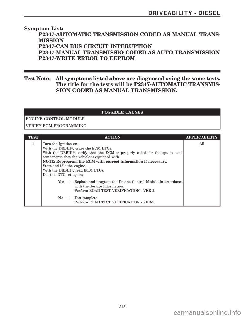
Symptom List:
P2347-AUTOMATIC TRANSMISSION CODED AS MANUAL TRANS-
MISSION
P2347-CAN BUS CIRCUIT INTERUPTION
P2347-MANUAL TRANSMISSIO CODED AS AUTO TRANSMISSION
P2347-WRITE ERROR TO EEPROM
Test Note: All symptoms listed above are diagnosed using the same tests.
The title for the tests will be P2347-AUTOMATIC TRANSMIS-
SION CODED AS MANUAL TRANSMISSION.
POSSIBLE CAUSES
ENGINE CONTROL MODULE
VERIFY ECM PROGRAMMING
TEST ACTION APPLICABILITY
1 Turn the Ignition on.
With the DRBIIIt, erase the ECM DTCs.
With the DRBIIIt, verify that the ECM is properly coded for the options and
components that the vehicle is equipped with.
NOTE: Reprogram the ECM with correct information if necessary.
Start and idle the engine.
With the DRBIIIt, read ECM DTCs.
Did this DTC set again?All
Ye s!Replace and program the Engine Control Module in accordance
with the Service Information.
Perform ROAD TEST VERIFICATION - VER-2.
No!Test complete.
Perform ROAD TEST VERIFICATION - VER-2.
213
DRIVEABILITY - DIESEL
Page 702 of 2305

DIAGNOSTIC TEST PROCEDURES — TELL US!
DaimlerChrysler Corporation is constantly working to provide the technician the best diagnostic manuals possible.
Your comments and recommendations regarding the diagnostic manuals and procedures are appreciated.
To best understand your suggestion, please complete the form giving us as much detail as possible.
ModelYearBody TypeEngine
TransmissionVehicle MileageMDH
Diagnostic ProcedureBook No.Page
Comments/recommendations (if necessary, draw sketch)
Name
Submitted by:
Address
City/State/Zip
Business Phone #
All comments become property of DaimlerChrysler Corporation and may be used without compensation.