2006 MERCEDES-BENZ SPRINTER manual transmission
[x] Cancel search: manual transmissionPage 1087 of 2305
²Grounds and ground connectors are identified
with a ªGº and follow the same series numbering as
the in-line connectors.
²Splices are identified with an ªSº and follow the
same series numbering as the in-line connectors.
²Component connectors are identified by the com-
ponent name instead of a number. Multiple connec-
tors on a component use a C1, C2, etc. identifier.
LOCATIONS
Section 8W-91 contains connector/ground/splice
location illustrations. The illustrations contain the
connector name (or number)/ground number/splice
number and component identification. Connector/
ground/splice location charts in section 8W-91 refer-
ence the figure numbers of the illustrations.
The abbreviation T/O is used in the component
location section to indicate a point in which the wir-
ing harness branches out to a component. The abbre-
viation N/S means Not Shown in the illustrations
WARNINGS - GENERAL
WARNINGSprovide information to prevent per-
sonal injury and vehicle damage. Below is a list of
general warnings that should be followed any time a
vehicle is being serviced.
WARNING: ALWAYS WEAR SAFETY GLASSES FOR
EYE PROTECTION.
WARNING: USE SAFETY STANDS ANYTIME A PRO-
CEDURE REQUIRES BEING UNDER A VEHICLE.
WARNING: BE SURE THAT THE IGNITION SWITCH
ALWAYS IS IN THE OFF POSITION, UNLESS THE
PROCEDURE REQUIRES IT TO BE ON.
WARNING: SET THE PARKING BRAKE WHEN
WORKING ON ANY VEHICLE. AN AUTOMATIC
TRANSMISSION SHOULD BE IN PARK. A MANUAL
TRANSMISSION SHOULD BE IN NEUTRAL.
WARNING: OPERATE THE ENGINE ONLY IN A
WELL-VENTILATED AREA.
WARNING: KEEP AWAY FROM MOVING PARTS
WHEN THE ENGINE IS RUNNING, ESPECIALLY THE
FAN AND BELTS.
WARNING: TO PREVENT SERIOUS BURNS, AVOID
CONTACT WITH HOT PARTS SUCH AS THE RADIA-TOR, EXHAUST MANIFOLD(S), TAIL PIPE, CATA-
LYTIC CONVERTER AND MUFFLER.
WARNING: DO NOT ALLOW FLAME OR SPARKS
NEAR THE BATTERY. GASES ARE ALWAYS
PRESENT IN AND AROUND THE BATTERY.
WARNING: ALWAYS REMOVE RINGS, WATCHES,
LOOSE HANGING JEWELRY AND AVOID LOOSE
CLOTHING.
DIAGNOSIS AND TESTING
WIRING HARNESS
TROUBLESHOOTING TOOLS
When diagnosing a problem in an electrical circuit
there are several common tools necessary. These tools
are listed and explained below.
²Jumper Wire - This is a test wire used to con-
nect two points of a circuit. It can be used to bypass
an open in a circuit.
WARNING: NEVER USE A JUMPER WIRE ACROSS
A LOAD, SUCH AS A MOTOR, CONNECTED
BETWEEN A BATTERY FEED AND GROUND.
²Voltmeter - Used to check for voltage on a cir-
cuit. Always connect the black lead to a known good
ground and the red lead to the positive side of the
circuit.
CAUTION: Most of the electrical components used
in today's vehicles are Solid State. When checking
voltages in these circuits, use a meter with a 10 -
megohm or greater impedance rating.
²Ohmmeter - Used to check the resistance
between two points of a circuit. Low or no resistance
in a circuit means good continuity.
CAUTION: Most of the electrical components used
in today's vehicles are Solid State. When checking
resistance in these circuits use a meter with a 10 -
megohm or greater impedance rating. In addition,
make sure the power is disconnected from the cir-
cuit. Circuits that are powered up by the vehicle's
electrical system can cause damage to the equip-
ment and provide false readings.
²Probing Tools - These tools are used for probing
terminals in connectors (Fig. 4). Select the proper
size tool from Special Tool Package 6807, and insert
it into the terminal being tested. Use the other end
of the tool to insert the meter probe.
8W - 01 - 6 8W-01 WIRING DIAGRAM INFORMATIONVA
Page 1616 of 2305
CAUTION: Oil thread and head contact surfaces of
bolts that retain the crankshaft bearing caps;
tighten bolts from inside to outside, beginning at
the fit bearing. Rotate crankshaft to check clear-
ance.
(1) Install crankshaft.
CAUTION: The crankshaft bearing caps are num-
bered consecutively, beginning with the first crank-
shaft bearing cap at the front of the engine.
Attention must be paid to the way the crankshaft
bearing caps fit. If correctly installed, the lug, or
raised boss, on the crankshaft bearing cap is point-
ing to the left when viewed in the direction of travel
(intake side).
(2) Install the crankshaft bearing caps. Tighten
bolts in two stages. 55N´m (40.5 lbs. ft.), then 90É.
(3) Install the pistons (Refer to 9 - ENGINE/EN-
GINE BLOCK/PISTON & CONNECTING ROD -
INSTALLATION).
(4) Install the end cover (Refer to 9 - ENGINE/EN-
GINE BLOCK/CRANKSHAFT OIL SEAL - REAR -
INSTALLATION).
(5) Install the timing case cover (Refer to 9 -
ENGINE/VALVE TIMING/TIMING BELT / CHAIN
COVER(S) - INSTALLATION).
(6) Install the engine (Refer to 9 - ENGINE -
INSTALLATION).
(7) Fill the crankcase with the correct engine oil,
to the proper level. Refer to the owners manual for
specifications.
(8) Fill the cooling system with the proper coolant,
to the proper level (Refer to 7 - COOLING/ENGINE/
COOLANT - STANDARD PROCEDURE).
(9) Connect the negative battery cable.
WARNING: USE EXTREME CAUTION WHEN THE
ENGINE IS OPERATING. DO NOT STAND IN A
DIRECT LINE WITH THE FAN. DO NOT PUT YOUR
HANDS NEAR THE PULLEYS, BELTS, OR FAN. DO
NOT WEAR LOOSE CLOTHES.
(10) Start engine and inspect for leaks. Care must
be taken to observe the fuel system warning (Refer to
14 - FUEL SYSTEM - WARNING).
CRANKSHAFT OIL SEAL -
REAR
REMOVAL
This must be done with the transmission removed
from the vehicle.
(1) Disconnect the negative battery cable.
(2) Raise and support the vehicle.
(3) Drain the engine oil.NOTE: Loosen all of the oil pan bolts to assure that
the oil pan gasket is not damaged when removing
the rear main oil seal and end cover assembly.
NOTE: Inspect the oil pan gasket for damage. If the
oil pan gasket is damaged, remove the oil pan and
replace the oil pan gasket.
(4) Loosen the oil pan bolts.
(5) Remove the flywheel.
CAUTION: Care must be taken when removing the
rear main seal and adaptor assembly. Failure to do
so will result in damage to the oil pan gasket.
(6) Remove the rear main seal/adaptor retaining
bolts and carefully pry the adaptor from the crank-
case at the adaptor shoulders (Fig. 33).
VAENGINE 9 - 41
Page 1911 of 2305
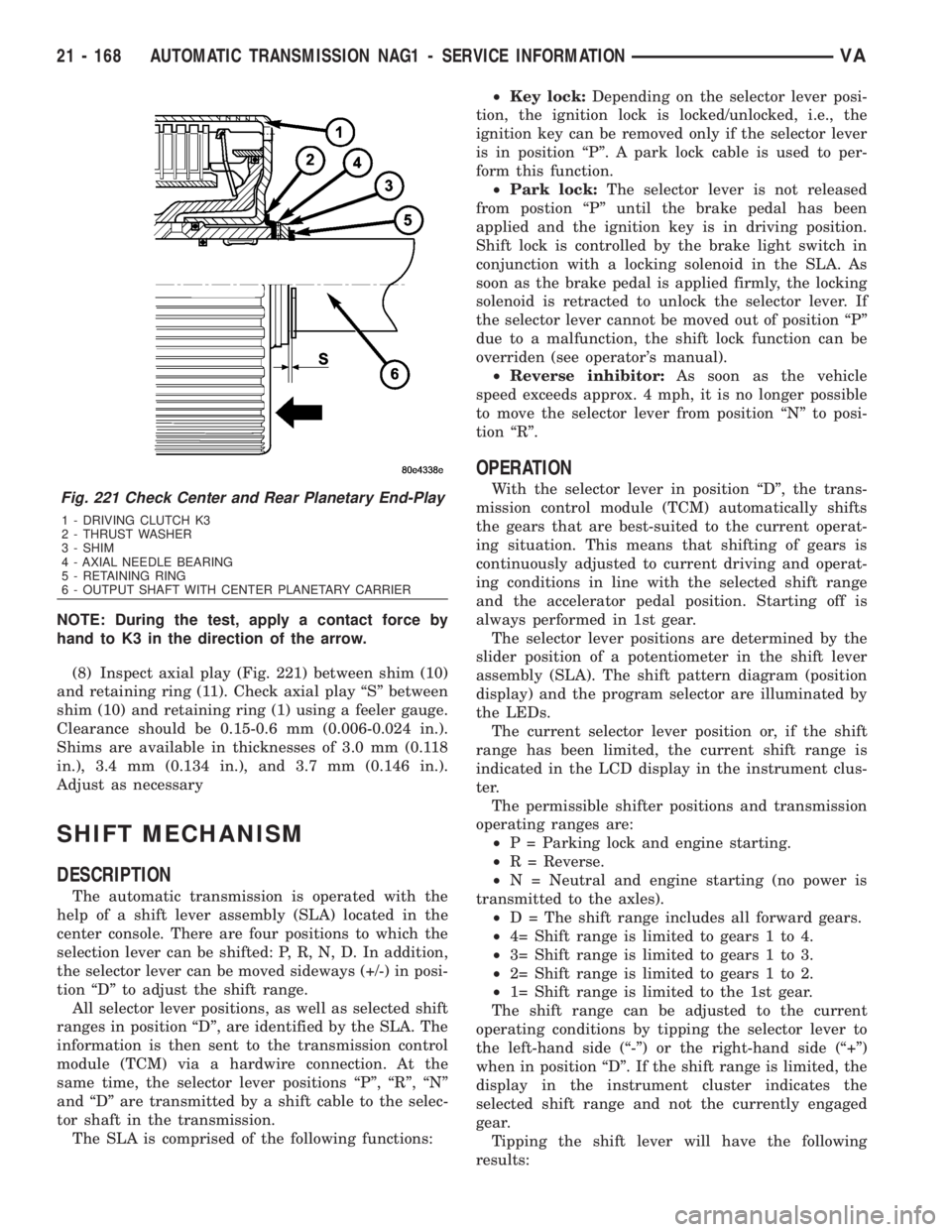
NOTE: During the test, apply a contact force by
hand to K3 in the direction of the arrow.
(8) Inspect axial play (Fig. 221) between shim (10)
and retaining ring (11). Check axial play ªSº between
shim (10) and retaining ring (1) using a feeler gauge.
Clearance should be 0.15-0.6 mm (0.006-0.024 in.).
Shims are available in thicknesses of 3.0 mm (0.118
in.), 3.4 mm (0.134 in.), and 3.7 mm (0.146 in.).
Adjust as necessary
SHIFT MECHANISM
DESCRIPTION
The automatic transmission is operated with the
help of a shift lever assembly (SLA) located in the
center console. There are four positions to which the
selection lever can be shifted: P, R, N, D. In addition,
the selector lever can be moved sideways (+/-) in posi-
tion ªDº to adjust the shift range.
All selector lever positions, as well as selected shift
ranges in position ªDº, are identified by the SLA. The
information is then sent to the transmission control
module (TCM) via a hardwire connection. At the
same time, the selector lever positions ªPº, ªRº, ªNº
and ªDº are transmitted by a shift cable to the selec-
tor shaft in the transmission.
The SLA is comprised of the following functions:²Key lock:Depending on the selector lever posi-
tion, the ignition lock is locked/unlocked, i.e., the
ignition key can be removed only if the selector lever
is in position ªPº. A park lock cable is used to per-
form this function.
²Park lock:The selector lever is not released
from postion ªPº until the brake pedal has been
applied and the ignition key is in driving position.
Shift lock is controlled by the brake light switch in
conjunction with a locking solenoid in the SLA. As
soon as the brake pedal is applied firmly, the locking
solenoid is retracted to unlock the selector lever. If
the selector lever cannot be moved out of position ªPº
due to a malfunction, the shift lock function can be
overriden (see operator's manual).
²Reverse inhibitor:As soon as the vehicle
speed exceeds approx. 4 mph, it is no longer possible
to move the selector lever from position ªNº to posi-
tion ªRº.
OPERATION
With the selector lever in position ªDº, the trans-
mission control module (TCM) automatically shifts
the gears that are best-suited to the current operat-
ing situation. This means that shifting of gears is
continuously adjusted to current driving and operat-
ing conditions in line with the selected shift range
and the accelerator pedal position. Starting off is
always performed in 1st gear.
The selector lever positions are determined by the
slider position of a potentiometer in the shift lever
assembly (SLA). The shift pattern diagram (position
display) and the program selector are illuminated by
the LEDs.
The current selector lever position or, if the shift
range has been limited, the current shift range is
indicated in the LCD display in the instrument clus-
ter.
The permissible shifter positions and transmission
operating ranges are:
²P = Parking lock and engine starting.
²R = Reverse.
²N = Neutral and engine starting (no power is
transmitted to the axles).
²D = The shift range includes all forward gears.
²4= Shift range is limited to gears 1 to 4.
²3= Shift range is limited to gears 1 to 3.
²2= Shift range is limited to gears 1 to 2.
²1= Shift range is limited to the 1st gear.
The shift range can be adjusted to the current
operating conditions by tipping the selector lever to
the left-hand side (ª-º) or the right-hand side (ª+º)
when in position ªDº. If the shift range is limited, the
display in the instrument cluster indicates the
selected shift range and not the currently engaged
gear.
Tipping the shift lever will have the following
results:Fig. 221 Check Center and Rear Planetary End-Play
1 - DRIVING CLUTCH K3
2 - THRUST WASHER
3 - SHIM
4 - AXIAL NEEDLE BEARING
5 - RETAINING RING
6 - OUTPUT SHAFT WITH CENTER PLANETARY CARRIER
21 - 168 AUTOMATIC TRANSMISSION NAG1 - SERVICE INFORMATIONVA
Page 1912 of 2305
²Tipping the selector lever toward ª-º one
time after another:The shift range is reduced in
descending sequence by one gear each time, i.e., from
D-4-3-2-1.Iftheselected limitation of the shift
range would result in a downshift causing excessive
engine speed, the shifting is not executed and the
engaged gear as well as the shift range remain
unchanged. This is to prevent the engine from over-
speeding. Engine retardation is low with the selector
lever in position ªDº. To make use of the full braking
power of the engine, ªmanualº downshifting by tip-
ping the lever towards the left-hand side is recom-
mended. If this has been done, subsequent upshifting
must be carried out manually as well.
²Tipping the selector lever toward ª-º and
holding it in this position:The currently engaged
gear in range ªDº is indicated in the instrument clus-
ter display and the shift range is limited to this gear.
²Tipping the selector lever toward ª+º one
time after another:The shift range is increased by
one gear each time and the increased shift range is
displayed in the instrument cluster; possibly, the
transmission upshifts to a faster gear.
²Tipping the selector lever toward ª+º sev-
eral times:The shift range is increased by one gear
each time the lever is tipped until the shift range
ends up in ªDº.
²Tipping the selector lever toward ª+º and
holding it in this position:The shift range is
extended immediately to ªDº, shift ranges are indi-
cated in ascending sequence; possibly, the transmis-
sion upshifts to a faster gear due to the extension of
the shift range.
REMOVAL
(1) Move selector lever to position ªDº.
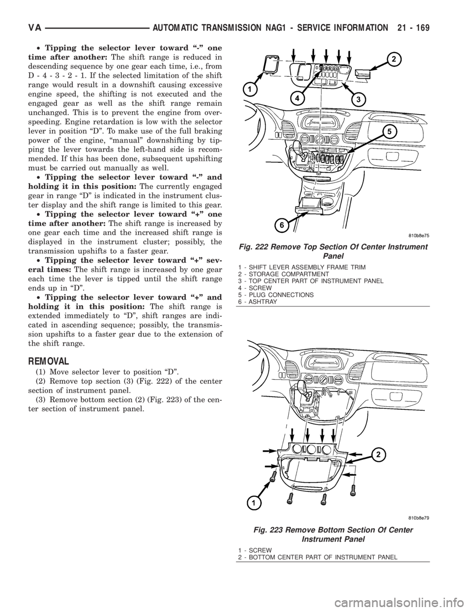
(2) Remove top section (3) (Fig. 222) of the center
section of instrument panel.
(3) Remove bottom section (2) (Fig. 223) of the cen-
ter section of instrument panel.
Fig. 222 Remove Top Section Of Center Instrument
Panel
1 - SHIFT LEVER ASSEMBLY FRAME TRIM
2 - STORAGE COMPARTMENT
3 - TOP CENTER PART OF INSTRUMENT PANEL
4 - SCREW
5 - PLUG CONNECTIONS
6 - ASHTRAY
Fig. 223 Remove Bottom Section Of Center
Instrument Panel
1 - SCREW
2 - BOTTOM CENTER PART OF INSTRUMENT PANEL
VAAUTOMATIC TRANSMISSION NAG1 - SERVICE INFORMATION 21 - 169
Page 2100 of 2305
SYSTEM EMPTY
(1) Evacuate the refrigerant system to the lowest
degree of vacuum possible (approximately 28 in Hg.)
(Refer to 24 - HEATING & AIR CONDITIONING/
PLUMBING - STANDARD PROCEDURE - REFRIG-
ERANT SYSTEM EVACUATE). Determine if the
system holds a vacuum for 15 minutes. If vacuum is
held, a leak is probably not present. If system will
not maintain vacuum level, proceed to Step 2.
(2) Prepare and dispense 0.284 kilograms (10
ounces) of R-134a refrigerant into the evacuated
refrigerant system (Refer to 24 - HEATING & AIR
CONDITIONING/PLUMBING - STANDARD PRO-
CEDURE - REFRIGERANT SYSTEM CHARGE) and
proceed to Step 1 of the System Low procedure.
SYSTEM LOW
(1) Position the vehicle in a wind free work area.
This will aid in detecting small leaks.
(2) Operate the heating-A/C system with the
engine at idle under the following conditions for at
least five minutes.
²Doors or windows open
²Transmission in Park
²A/C-heater controls set to outside air, full cool,
panel mode, high blower and with A/C compressor
engaged
CAUTION: A leak detector only designed for R-12
refrigerant will not detect leaks in a R-134a refriger-
ant system.
(3) Shut the vehicle Off and wait 2-7 minutes.
Then use an electronic leak detector that is designed
to detect R-134a refrigerant and search for leaks. Fit-
tings, lines or components that appear to be oily usu-
ally indicate a refrigerant leak. To inspect the A/C
evaporator for leaks, insert the leak detector probe
into the drain tube opening or an air outlet. A dye for
R-134a is available to aid in leak detection. Use only
DaimlerChrysler approved refrigerant dye.
STANDARD PROCEDURE
REFRIGERANT SYSTEM SERVICE EQUIPMENT
WARNING: Eye protection must be worn when ser-
vicing an A/C refrigerant system. Turn off (rotate
clockwise) all valves on the equipment being used,
before connecting to or disconnecting from the
refrigerant system. Failure to observe these warn-
ings may result in possible personal injury.
WARNING: Refer to the applicable warnings and
cautions for this system before performing the fol-
lowing operation (Refer to 24 - HEATING & AIR
CONDITIONING/PLUMBING - WARNINGS) and (Referto 24 - HEATING & AIR CONDITIONING/PLUMBING -
CAUTIONS). Failure to follow the warnings and cau-
tions could result in possible personal injury or
death.
When servicing the air conditioning system, a
R-134a refrigerant recovery/recycling/charging sta-
tion that meets SAE Standard J2210 must be used.
Contact an automotive service equipment supplier for
refrigerant recovery/recycling/charging equipment.
Refer to the operating instructions supplied by the
equipment manufacturer for proper care and use of
this equipment.
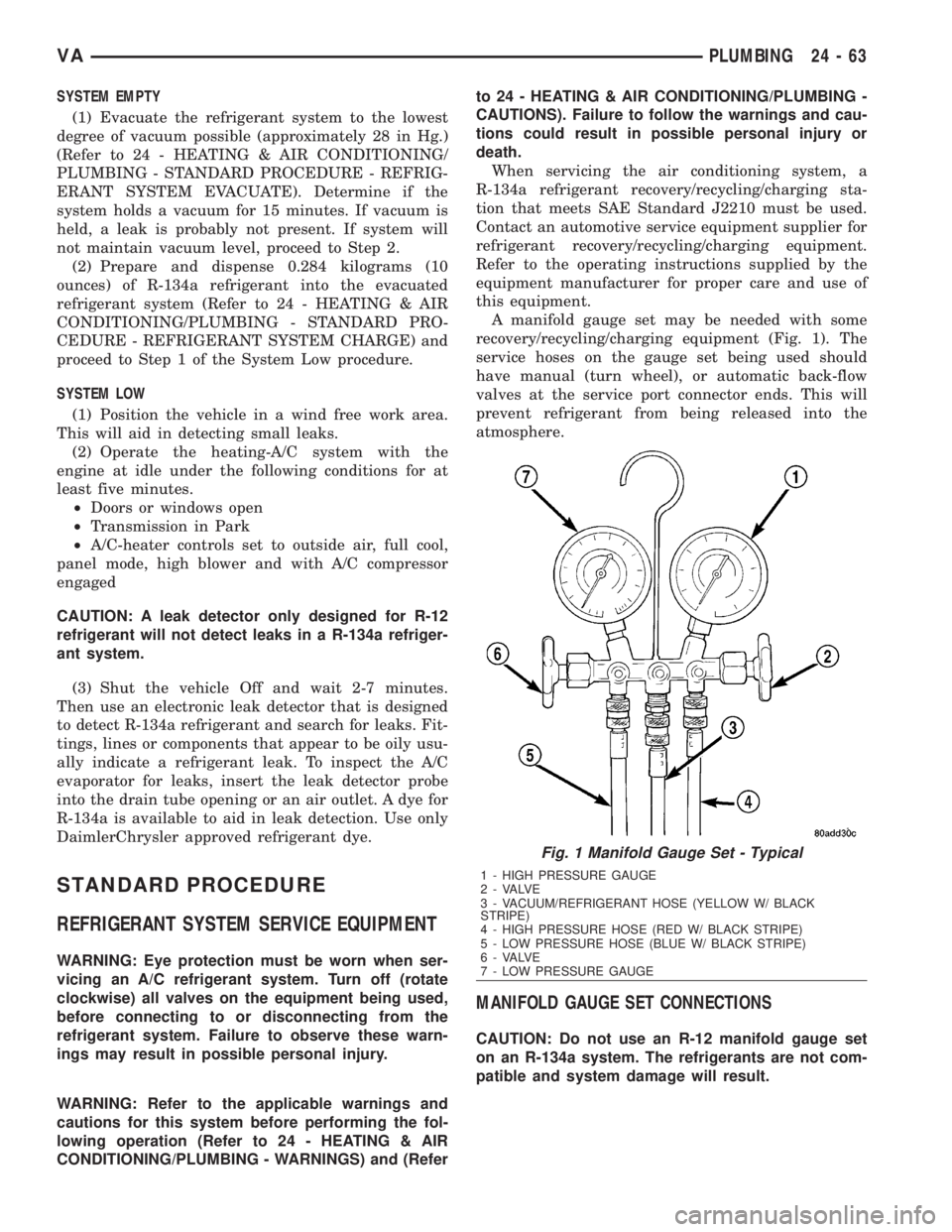
A manifold gauge set may be needed with some
recovery/recycling/charging equipment (Fig. 1). The
service hoses on the gauge set being used should
have manual (turn wheel), or automatic back-flow
valves at the service port connector ends. This will
prevent refrigerant from being released into the
atmosphere.
MANIFOLD GAUGE SET CONNECTIONS
CAUTION: Do not use an R-12 manifold gauge set
on an R-134a system. The refrigerants are not com-
patible and system damage will result.
Fig. 1 Manifold Gauge Set - Typical
1 - HIGH PRESSURE GAUGE
2 - VALVE
3 - VACUUM/REFRIGERANT HOSE (YELLOW W/ BLACK
STRIPE)
4 - HIGH PRESSURE HOSE (RED W/ BLACK STRIPE)
5 - LOW PRESSURE HOSE (BLUE W/ BLACK STRIPE)
6 - VALVE
7 - LOW PRESSURE GAUGE
VAPLUMBING 24 - 63
Page 2159 of 2305
INSIDE HANDLE ACTUATOR......23-33, 23-36
INSTRUMENT CLUSTER................8J-2
INSTRUMENT PANEL ANTENNA CABLE....8A-2
INSTRUMENT PANEL ASSEMBLY........23-59
INSTRUMENT PANEL CENTER BEZEL.....23-57
INSTRUMENT PANEL DUCTS...........24-51
INTAKE AIR PRESSURE SENSOR........14-43
INTAKE AIR TEMPERATURE SENSOR.....14-42
INTAKE MANIFOLD....................9-65
INTERIOR..........................23-70
INTERMEDIATE SHAFT.................19-4
INTERNATIONAL SYMBOLS...............0-9
INTERNATIONAL SYMBOLS...........Intro.-2
INTRUSION SENSOR...................8Q-1
IN - CAR TEMPERATURE SENSOR.......24-21
JUMP STARTING.......................0-6
KEY / LOCK CYLINDER.................19-5
KNUCKLE.............................2-5
LAMPS / LIGHTING - EXTERIOR..........8L-2
LAMPS / LIGHTING - INTERIOR.........8L-28
LATCH RELEASE CABLE...............23-52
LATCH RELEASE HANDLE..............23-52
LATCH STRIKER.....................23-18
LATCH ..................23-18, 23-33, 23-52
LATCH / LOCK CONTROL...............23-38
LATERAL ACCELERATION SENSOR........5-33
LEFT MOUNT.........................9-55
LEVER..............................5-26
LICENSE PLATE BRACKET..............23-48
LICENSE PLATE LAMP BULB...........8L-19
LICENSE PLATE LAMP UNIT............8L-19
LINKAGE............................19-9
LIQUID LINE........................24-77
LOCK CYLINDER.....................23-18
LOW BEAM HEADLAMP BULB..........8L-20
LOW FUEL INDICATOR................8J-19
LOW OIL LEVEL INDICATOR............8J-20
LOWER BALL JOINT....................2-6
LOWER CONTROL ARM.................2-6
LOWER ROLLER ARM.................23-37
MAINTENANCE INDICATOR.............8J-20
MAINTENANCE SCHEDULES..............0-8
MALFUNCTION INDICATOR LAMP (MIL) . . . 8J-21
MANIFOLD AIR FLOW (MAF) SENSOR....14-44
MASTER CYLINDER...................5-17
MASTER LOCK SWITCH................8N-1
METRIC SYSTEM...................Intro.-6
MODE DOOR CABLES.................24-21
MULTI - FUNCTION INDICATOR..........8J-22
MULTI - FUNCTION SWITCH............8L-21
O2 SENSOR.........................14-45
ODOMETER.........................8J-22
OIL COOLER & LINES..................9-56
OIL FILTER ..........................9-57
OIL JET .............................9-57
OIL PAN .............................9-58
OIL PUMP...........................9-61
OIL PUMP.........................21-154
OIL SENSOR.........................9-64
OIL ................................9-56
OPENING DIMENSIONS................23-93
OUTPUT SHAFT BEARING.............21-156
OUTPUT SHAFT SEAL................21-159
PAINT TOUCH - UP...................23-77
PAINT.............................23-77
PARK BRAKE INDICATOR..............8J-23
PARK BRAKE SWITCH.................8L-21
PARK LOCK CABLE..................21-160
PARKING BRAKE......................5-23
PASSENGER AIRBAG BRACKET.........8O-27
PASSENGER AIRBAG.................8O-24
PASSENGER HEATED SEAT SWITCH.....8G-13
PEDAL..............................5-19
PISTON & CONNECTING ROD............9-45
PISTON RINGS.......................9-52
PISTONS..........................21-163
PLANETARY GEARTRAIN..............21-164
PLUMBING.........................24-61
POWER BRAKE BOOSTER...............5-19
POWER DISTRIBUTION CENTER.......8W-97-3
POWER DISTRIBUTION..............8W-97-1
POWER MIRROR SWITCH..............8N-3
POWER MIRRORS....................8N-3
POWER OUTLET
...................8W-97-3
POWER WINDOW SWITCH
..............8N-5
POWER WINDOWS
....................8N-5
PROP ROD
.........................23-53
PROPELLER SHAFT
.................3-1, 3-7PUMP.............................19-11
QUARTER TRIM PANEL................23-74
QUARTER WINDOW..................23-84
RADIATOR CROSSMEMBER............23-49
RADIATOR FAN.......................7-14
RADIATOR PRESSURE CAP..............7-19
RADIATOR...........................7-17
RADIO..............................8A-2
RAIN SENSOR CONTROL MODULE......8R-15
RAIN SENSOR.......................8R-12
REAR AXLE..........................3-12
REAR A / C CONDENSER FAN...........24-83
REAR A / C EVAPORATOR..............24-84
REAR A / C EXPANSION VALVE..........24-85
REAR BUMPER - STEP.................13-2
REAR CROSSMEMBER - TRANSMISSION . . 13-11
REAR DISCHARGE LINE...............24-88
REAR FASCIA........................13-3
REAR LATCH STRIKER................23-40
REAR LATCH........................23-40
REAR LIQUID LINE...................24-91
REAR RECEIVER / DRIER..............24-94
REAR REFRIGERANT RESERVOIR........24-95
REAR SEAT BACK SHIELD..............23-82
REAR SEAT BELT & RETRACTOR........8O-28
REAR SEAT BELT BUCKLE.............8O-30
REAR SIDE MARKER LAMP BULB.......8L-22
REAR SUCTION LINE..................24-96
REAR TURN LAMP BULB..............8L-23
REAR VIEW MIRROR.................23-75
REAR WHEEL SPEED SENSOR...........5-31
REAR WINDOW DEFOGGER GRID........8G-7
REAR WINDOW DEFOGGER RELAY.......8G-3
REAR WINDOW DEFOGGER SWITCH......8G-4
REAR...............................2-11
RECEIVER / DRIER...................24-79
RECIRCULATION DOOR ACTUATOR......24-22
REFRIGERANT LINE COUPLER..........24-98
REFRIGERANT OIL...................24-81
REFRIGERANT.......................24-80
RELAY...........................8W-97-4
REMOTE KEYLESS ENTRY
TRANSMITTER.......................8N-1
REPEATER LAMP BULB................8L-23
REPEATER LAMP UNIT................8L-24
RESTRAINTS.........................8O-2
RIGHT MOUNT.......................9-56
ROTORS............................5-20
SAFETY LATCH......................23-53
SEAL - PINION........................3-39
SEAT ADJUSTERS - FRONT.............23-81
SEAT BACK CUSHION / COVER - REAR....23-82
SEAT BACK - FRONT..................23-80
SEAT BELT SWITCH..................8O-31
SEAT BELT TENSIONER................8O-32
SEAT BELT TURNING LOOP ADJUSTER . . . 8O-33
SEAT CUSHION - FRONT...............23-80
SEAT CUSHION / COVER - REAR.........23-83
SEATBELT INDICATOR.................8J-24
SEAT - FRONT.......................23-79
SEAT - REAR........................23-81
SECURITY SYSTEM MODULE............8Q-2
SENTRY KEY REMOTE ENTRY MODULE....8Q-2
SERVO..............................8P-2
SHAFT - AXLE DUAL REAR WHEELS......3-27
SHAFT - AXLE SINGLE REAR WHEEL......3-23
SHIFT MECHANISM..................21-168
SHOCK..............................2-13
SHOES..............................5-27
SIDE CURTAIN AIRBAG................8O-35
SIDE IMPACT SENSOR................8O-39
SIDE VIEW MIRROR..................23-49
SIDE VIEW MIRROR - GLASS...........23-50
SIREN..............................8Q-4
SLIDING DOOR......................23-40
SOLENOID.........................21-171
SPARE TIRE CARRIER.................22-12
SPEAKER............................8A-2
SPEED CONTROL.....................8P-1
SPEEDOMETER......................8J-25
SPRING CLAMP PLATES.................2-8
SPRING SHACKLE.....................2-15
SPRING STOP PLATES..................2-9
SPRING
.........................2-7, 2-14
STABILIZER BAR
..................2-9, 2-15
STABILIZER LINK
.................2-10, 2-16
STABILIZER
.........................23-45
STARTER MOTOR RELAY
..............8F-35STARTER MOTOR....................8F-33
STARTING SYSTEM...................8F-28
STEERING ANGLE SENSOR..............5-32
STEERING COLUMN OPENING COVER....23-68
STEERING WHEEL.....................19-6
STEERING...........................19-1
STEPWELL SCUFF PADS...............23-75
STRUT..............................2-10
SUCTION LINE.......................24-81
SUN VISOR.........................23-76
SUPPORT PLATE......................5-23
SUPPRESSOR FILTER - REAR BLOWER
MOTOR............................24-41
SUPPRESSOR FILTER - REAR
CONDENSER FAN....................24-43
SWITCH.............................8P-3
TACHOMETER.......................8J-25
TAIL LAMP UNIT.....................8L-25
TAILPIPE............................11-3
TEMPERATURE CONTROL..............24-38
TEMPERATURE SENSOR...............24-40
TEMPERATURE SENSOR / PARK -
NEUTRAL CONTACT..................21-176
TERMINAL........................Intro.-10
THREADED HOLE REPAIR.............Intro.-6
TIE ROD END ........................19-10
TIME DELAY RELAY....................8L-35
TIMING CHAIN AND SPROCKETS.........9-72
TIMING CHAIN COVER.................9-70
TIMING CHAIN TENSIONER..............9-81
TIRES..............................22-7
TIRES / WHEELS......................22-1
TONE WHEEL........................5-32
TOP COVER.........................23-67
TOP COVER - CLUSTER................23-64
TOP COVER - TRAY...................23-65
TORQUE CONVERTER HUB SEAL.......21-184
TORQUE CONVERTER................21-178
TORQUE REFERENCES...............Intro.-9
TOWING.............................0-7
TRACTION CONTROL INDICATOR........8J-26
TRACTION CONTROL MALFUNCTION
INDICATOR.........................8J-27
TRAILER HITCH......................13-11
TRANSMISSION CONTROL MODULE......8E-6
TRANSPONDER KEY...................8Q-5
TRIM PANEL.............23-18, 23-34, 23-46
TURBOCHARGER SYSTEM..............11-3
TURBOCHARGER......................11-6
TURN SIGNAL INDICATOR..............8J-27
TURN SIGNAL RELAY.................8L-26
UNDERBODY LINES..................24-100
UPPER ROLLER ARM.................23-36
VACUUM PUMP.......................9-54
VALVE COOLER.......................25-6
VALVE SPRINGS......................9-35
VALVE STEM SEALS...................9-34
VALVE ..............................25-5
VEHICLE IDENTIFICATION NUMBER.....Intro.-1
VEHICLE THEFT SECURITY..............8Q-1
VIBRATION DAMPER...................9-53
VOLTAGE REGULATOR.................8F-24
WAIT - TO - START INDICATOR..........8J-28
WASHER FLUID INDICATOR............8J-29
WASHER FLUID LEVEL SWITCH.........8R-16
WASHER HOSES / TUBES..............8R-18
WASHER NOZZLE....................8R-18
WASHER PUMP / MOTOR..............8R-19
WASHER RESERVOIR.................8R-21
WATER IN FUEL SENSOR..............14-30
WATER PUMP........................7-20
WATER VALVE .......................24-83
WATER - IN - FUEL INDICATOR..........8J-29
WHEEL ALIGNMENT...................2-17
WHEELS...........................22-13
WINDOW MOTOR.....................8N-5
WINDOW REGULATOR - MANUAL........23-21
WINDOW REGULATOR - POWER........23-20
WINDSHIELD........................23-85
WIPER ARM........................8R-23
WIPER BLADE.......................8R-26
WIPER LINKAGE.....................8R-28
WIPER MOTOR......................8R-31
WIPER RELAY.......................8R-34
WIPERS/WASHERS....................8R-2
WIRING DIAGRAM INFORMATION......Intro.-1
YAW RATE SENSOR...................5-35
2 INDEXVA
Description Group-Page Description Group-Page Description Group-Page
Page 2166 of 2305
1.0 INTRODUCTION
The procedures contained in this manual include
all of the specifications, instructions, and graphics
needed to diagnose NAG1 Electronic Automatic
Transmission and Shift Lever Assembly problems.
The diagnostics in this manual are based on the
failure condition or symptom being present at the
time of diagnosis.
When repairs are required, refer to the appropri-
ate volume of the service information for the proper
removal and repair procedure.
READ THIS MANUAL BEFORE TRYING TO
DIAGNOSE A VEHICLE TROUBLE CODE.
Diagnostic procedures change every year. New
diagnostic systems may be added and/or carryover
systems may be enhanced. It is recommended that
you review the entire manual to become familiar
with all new and changed diagnostic procedures.
1.1 SYSTEM COVERAGE
This diagnostic procedures manual covers all
Sprinter (VA) equipped with a NAG1 Automatic
Transmission.
1.2 SIX -STEP TROUBLESHOOTING
PROCEDURE
Diagnosis of the NAG1 electronic transmission is
done in six basic steps:
Verification of complaint
Verification of any related symptoms
Symptom analysis
Problem isolation
Repair of isolated problem
Verification of proper operation
2.0 IDENTIFICATION OF
SYSTEM
The NAG1 Transmission family can be identified
by the presence of a 13 pin electrical connector, with
a bayonet lock on the right hand side of the trans-
mission. The connector is oriented horizontally.
3.0 SYSTEM DESCRIPTION AND
FUNCTIONAL OPERATION
3.1 GENERAL DESCRIPTION
The NAG1 electronic transmission is an electron-
ically controlled five speed transmission with a
controlled slip torque converter. The NAG1 elec-tronic transmission is a conventional transmission
in that it uses hydraulically applied clutches to shift
a planetary gear train. However, the electronic
control system replaces many of the mechanical and
hydraulic components used in conventional trans-
mission valve bodies.
The ratios for the gear stages are obtained by 3
planetary gear sets. Fifth Gear is designed as an
Overdrive with a high speed ratio. The gears are
actuated electronically/hydraulically. The electronic
control system enables precise adaptation of pres-
sures to the respective operating conditions and to
the engine output during a shift phase, which
results in a significant improvement in shift qual-
ity.
3.2 FUNCTIONAL OPERATION
The NAG1 electronic transmission has a fully
adaptive control system. The system performs its
functions based on continuous real-time sensor and
switch feedback information. In addition the TCM
receives information from the Shift Lever Assembly,
ECM (engine management) and ABS (chassis sys-
tems) controllers over the CAN bus. The CAN bus is
a high speed communication bus that allows real
time control capability between various controllers.
Most messages are sent every 20 milliseconds, this
means critical information can be shared between
the Transmission, Shifter, Engine and ABS control-
lers. The CAN bus is a two wire bus with aCAN C
Bus (+) circuitand aCAN C Bus (-) circuit. The
CAN bus uses a twisted pair of wires in the harness
to reduce the potential of radio and noise interfer-
ence. The CAN bus also uses a 120 ohm terminating
resistor in both the ECM and Sentry Key Remote
Entry Module (SKREEM) modules. The module
terminating resistance is measured across both
CAN bus circuits at the ECM or SKREEM module.
The control system automatically adapts to
changes in engine performance, vehicle speed, and
transmission temperature variations to provide
consistent shift quality. The control system ensures
that clutch operation during upshifting and down-
shifting is more responsive without increased
harshness. The TCM controls the actuation of sole-
noid valves for modulating shift pressure and gear
change. The required pressure level is calculated
from the load condition, engine speed. Power for the
transmission system is supplied through the Trans-
mission Relay. The TCM is located in the under the
drivers seat of the vehicle.
The Transmission Control Module (TCM) contin-
uously checks for electrical problems, mechanical
problems, and some hydraulic problems. When a
problem is sensed, the TCM stores a diagnostic
trouble code (DTC). Some of these codes cause the
transmission to go into9limp-in9or9default9mode.
1
GENERAL INFORMATION
Page 2169 of 2305
3.2.5 TRANSMISSION OPERATION AND
SHIFT SCHEDULING
The transmission covered in this manual has
unique shift schedules depending on the tempera-
ture of the transmission oil. The transmission oil
temperature has a decisive effect on the shift qual-
ity of the transmission. The shift schedule is modi-
fied to extend the life of the transmission while
operating under extreme conditions and to improve
driver comfort by modifying shift schedules.
The transmission oil temperature is measured
with a Temperature Sensor on the NAG1 transmis-
sion. The Temperature Sensor is an integral com-
ponent of the Transmission Solenoid assembly. If
the Temperature Sensor is causing a problem, a
DTC will be set in the TCM.
The Transmission Temperature Sensor is wired in
series with the Park /Neutral (P/N) switch. The P/N
switch is also located in the transmission. The trans-
mission temperature is only read by the TCM when
the P/N switch closes while in the R, D position.
When the shifter lever is in the park or neutral
position, the P/N switch opens and the temperature
being displayed is Engine temperature.
AutoStick Feature (If equipped)
This feature allows the driver to manually shift the
transaxle when the shift lever is moved sideways to
the (+ / -) in position D to adjust the shift range.
3.2.6 TRANSMISSION ADAPTIVES -
INITIALIZE AND STORE
Initialize Adaptive -This TCM function should be
used when a new transmission has been placed in
the vehicle. This command will reset the TCM
adaptive to the factory setting.
Store Adaptive -This command should be used
after the vehicle has been test driven by the tech-
nician to store any learned adaptive changes that
occurred during the test drive. During normal op-
eration adaptive are updated every 10 minutes.
Using this command the latest adaptive will be
written to the TCM immediately.
3.3 DIAGNOSTIC TROUBLE CODES
Diagnostic trouble codes (DTC's) are codes stored
by the Transmission Control Module (TCM) and the
Shift Lever Assembly Module (SLA) to help diag-
nose Transmission and Shifter problems. They are
viewed using the DRBIIItscan tool.
Always begin by performing a visual inspection of
the wiring, connectors, cooler lines and the trans-
mission. Any obvious wiring problems or leaks
should be repaired prior to performing any diagnos-
tic test procedures. Some engine driveability prob-lems can be misinterpreted as a transmission prob-
lem. Ensure that the engine is running properly
and that no ECM DTC's are present that could
cause a transmission complaint.
If there is a communication K-ABS,Shifter or
K-TCM circuit problem, trouble codes will not be
accessible until the problem is fixed. The DRBIIIt
will display an appropriate message. The following
is a possible list of causes for a bus problem:
± open or short to ground/battery in K line
circuit.
± internal failure of any module or component
connected to the K line circuit
Each diagnostic trouble code is diagnosed by
following a specific testing sequence. The diagnostic
test procedures contain step-by-step instructions
for determining the cause of a transmission diag-
nostic trouble code. Possible sources of the code are
checked and eliminated one by one. It is not neces-
sary to perform all of the tests in this book to
diagnose an individual code. These tests are based
on the problem being present at the time that the
test is run.
If the TCM records a DTC that will adversely
affect the vehicles transmission, it will request (via
the communication bus) that the ECM illuminate
the Malfunction Indicator Lamp (MIL). All trans-
mission DTC's will be stored in the TCM.
3.3.1 ACTIVE (HARD) CODE
Any Diagnostic Trouble Code (DTC) that is set
whenever the system or component is monitored is
an Active code. This means that the problem is
there every time the TCM checks that system or
component. Some codes will set immediately at
start up and others will require a road test under
specific conditions to set the DTC. It must be
determined if a code is Active (repeatable) or Stored
(Intermittent) before attempting diagnosis.
3.3.2 STORED (INTERMITTENT) CODE
A diagnostic trouble code that is not there every
time the TCM checks the circuit or function is a
Stored (Intermittent) code. Problems that come and
go like this are the most difficult to diagnose, they
must be looked for under the specific conditions
that cause them. If the DTC is reset (after an
ignition cycle) the DTC will be set to Stored (Inter-
mittent) status. A DTC status can be9Active9or
9Stored9(Intermittent). Active is when the DTC is
present in the controller and the transmission is in
the particular mode of operation for that DTC.
Stored means that the DTC occurred at some point,
but is not currently present, or the conditions have
not been right to check for the presence of the
problem, when a DTC is classified as Stored (Inter-
mittent), no TCM reaction is required.
4
GENERAL INFORMATION