Page 2170 of 2305
Emergency running function
If DTCs occur, safe-driving conditions must be re-
tained but full functionality of the transmission will
be limited to avoid damaging the automatic trans-
mission. In the event of certain DTCs the TCM
switches to emergency running. The TCM will store
the appropriate DTC codes and solenoids will be
de-energized (turned off)
The transmission effects will be:
²The last gear shifted remains in that position
²The modulating pressure and shift pressure in-
crease to maximum value
²The torque converter clutch is disengaged
(turned off)
Shifting manually after a DTC detection
NOTE: The vehicle can still be shifted
manually to 2nd or reverse gear.
To accomplish these shifts you must
Stop the vehicle
Turn the ignition off
Start the engine
Place the selector lever into D for 2nd gear
Place the selector lever into R for reverse gear
The emergency running function is retained until
the DTC is eliminated or the stored DTC code is
erased.
Stored (Intermittent) DTCs can be reset by cy-
cling the ignition switch
3.3.3 TROUBLE CODE ERASURE
Diagnostic Trouble Codes can be erased in two
ways. The first is to erase the DTC with the DRBIII
or scan tool. The second is if the DTC is no longer
present, the DTC is reset by the TCM (after an
ignition cycle), which will place the DTC in an
intermittent status (Stored DTC).
When there are no diagnostic trouble codes
stored in memory, the DRBIIItwill display
(NO DTC's DETECTED(
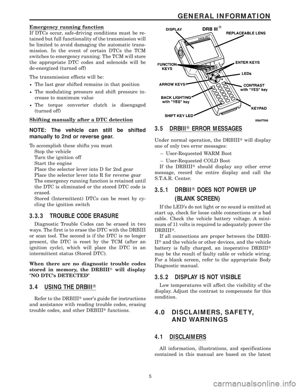
3.4 USING THE DRBIIIT
Refer to the DRBIIItuser's guide for instructions
and assistance with reading trouble codes, erasing
trouble codes, and other DRBIIItfunctions.
3.5 DRBIIITERROR MESSAGES
Under normal operation, the DRBIIItwill display
one of only two error messages:
± User-Requested WARM Boot
± User-Requested COLD Boot
If the DRBIIItshould display any other error
message, record the entire display and call the
S.T.A.R. Center.
3.5.1 DRBIIITDOES NOT POWER UP
(BLANK SCREEN)
If the LED's do not light or no sound is emitted at
start up, check for loose cable connections or a bad
cable. Check the vehicle battery voltage. A mini-
mum of 11 volts is required to adequately power the
DRBIIIt.
If all connections are proper between the DRBI-
IItand the vehicle or other devices, and the vehicle
battery is fully charged, an inoperative DRBIIIt
may be the result of faulty cable or vehicle wiring.
For a blank screen, refer to the appropriate Body
Diagnostic manual.
3.5.2 DISPLAY IS NOT VISIBLE
Low temperatures will affect the visibility of the
display. Adjust the contrast to compensate for this
condition.
4.0 DISCLAIMERS, SAFETY,
AND WARNINGS
4.1 DISCLAIMERS
All information, illustrations, and specifications
contained in this manual are based on the latest
5
GENERAL INFORMATION
Page 2171 of 2305

information available at the time of publication.
The right is reserved to make changes at any time
without notice.
4.2 SAFETY
4.2.1 TECHNICIAN SAFETY INFORMATION
WARNING: ENGINES PRODUCE CARBON
MONOXIDE THAT IS ODORLESS, CAUSES
SLOWER REACTION TIME, AND CAN LEAD
TO SERIOUS INJURY. WHEN THE ENGINE IS
OPERATING KEEP SERVICE AREAS WELL
VENTILATED OR ATTACH THE VEHICLE
EXHAUST SYSTEM TO THE SHOP EXHAUST
REMOVAL SYSTEM.
Set the parking brake and block the wheels before
testing or repairing the vehicle. If is especially
important to block the wheels on front-wheel drive
vehicles: the parking brake does not hold the drive
wheels.
Some operations in this manual require that
hydraulic tubes, hoses, and fittings, disconnected
for inspection or testing purposes. These systems,
when fully charged, contain fluid at high pressure.
Before disconnecting any hydraulic tubes, hoses,
and fittings, be sure that the system is fully depres-
surized.
When servicing a vehicle, always wear eye pro-
tection, and remove any metal jewelry such as
watchbands or bracelets that might make an inad-
vertent electrical contact.
When diagnosing a Transmission system prob-
lem, it is important to follow approved procedures
where applicable. These procedures can be found in
the service information. Following these procedures
is very important to the safety of individuals per-
forming diagnostic tests.
4.2.2 VEHICLE PREPARATION FOR
TESTING
Make sure the vehicle being tested has a fully
charged battery. If it does not, false diagnostic
DTC's or error messages may occur. It is extremely
important that accurate shift lever position data is
available to the TCM. The accuracy of any DTC
found in memory is doubtful unless the Shift Lever
Test, performed on the DRBIIItScan Tool, passes
without failure.
4.2.3 SERVICING SUB-ASSEMBLIES
Some components of the Transmission system are
intended to be serviced in assembly only. Attempt-
ing to remove or repair certain system sub-
components may result in personal injury and/orimproper system operation. Only those components
with approved repair and installation procedures in
the service information should be serviced.
4.2.4 DRBIIITSAFETY INFORMATION
WARNING: EXCEEDING THE LIMITS OF THE
DRBIIITMULTIMETER IS DANGEROUS. IT
CAN EXPOSE YOU TO SERIOUS OR
POSSIBLY FATAL INJURY. CAREFULLY
READ AND UNDERSTAND THE CAUTIONS
AND THE SPECIFICATION LIMITS.
²Follow the vehicle manufacturer's service speci-
fications at all times.
²Do not use the DRBIIItif it has been damaged.
²Do not use the test leads if the insulation is
damaged or if metal is exposed.
²To avoid electrical shock, do not touch the test
leads, tips or the circuit being tested.
²Choose the proper range and function for the
measurement. Do not try voltage or current mea-
surements that may exceed the rated capacity.
²Do not exceed the limits shown in the table.
FUNCTION INPUT LIMIT
Volts 0-500 volts peak AC
0-500 volts DC
Ohms (resistance)* 0-1.12 megohms
Frequency measured
Frequency generated0-10 khz
Temperature -58-1100ÉF
-50-600C
*Ohms cannot be measured if voltage is present.
Ohms can be measured only in a non-powered
circuit.
²Voltage between any terminal and ground must
not exceed 500v DC or 500v peak AC.
²Use caution when measured voltage above 25v
DC or 25v AC.
²The circuit being tested must be protected by a
10A fuse or circuit breaker.
²Use the low current shunt to measure circuits up
to 10A. Use the high current clamp to measure
circuits exceeding 10A.
²When testing for the presence of voltage or cur-
rent, make sure the meter is functioning cor-
rectly. Take a reading of a known voltage or
current before accepting a zero reading.
²When measuring current, connect the meter in
series with the load.
6
GENERAL INFORMATION
Page 2304 of 2305
DIAGNOSTIC TEST PROCEDURES — TELL US!
DaimlerChrysler Corporation is constantly working to provide the technician the best diagnostic manuals possible.
Your comments and recommendations regarding the diagnostic manuals and procedures are appreciated.
To best understand your suggestion, please complete the form giving us as much detail as possible.
ModelYearBody TypeEngine
TransmissionVehicle MileageMDH
Diagnostic ProcedureBook No.Page
Comments/recommendations (if necessary, draw sketch)
Name
Submitted by:
Address
City/State/Zip
Business Phone #
All comments become property of DaimlerChrysler Corporation and may be used without compensation.