2006 MERCEDES-BENZ SPRINTER stop start
[x] Cancel search: stop startPage 58 of 2305

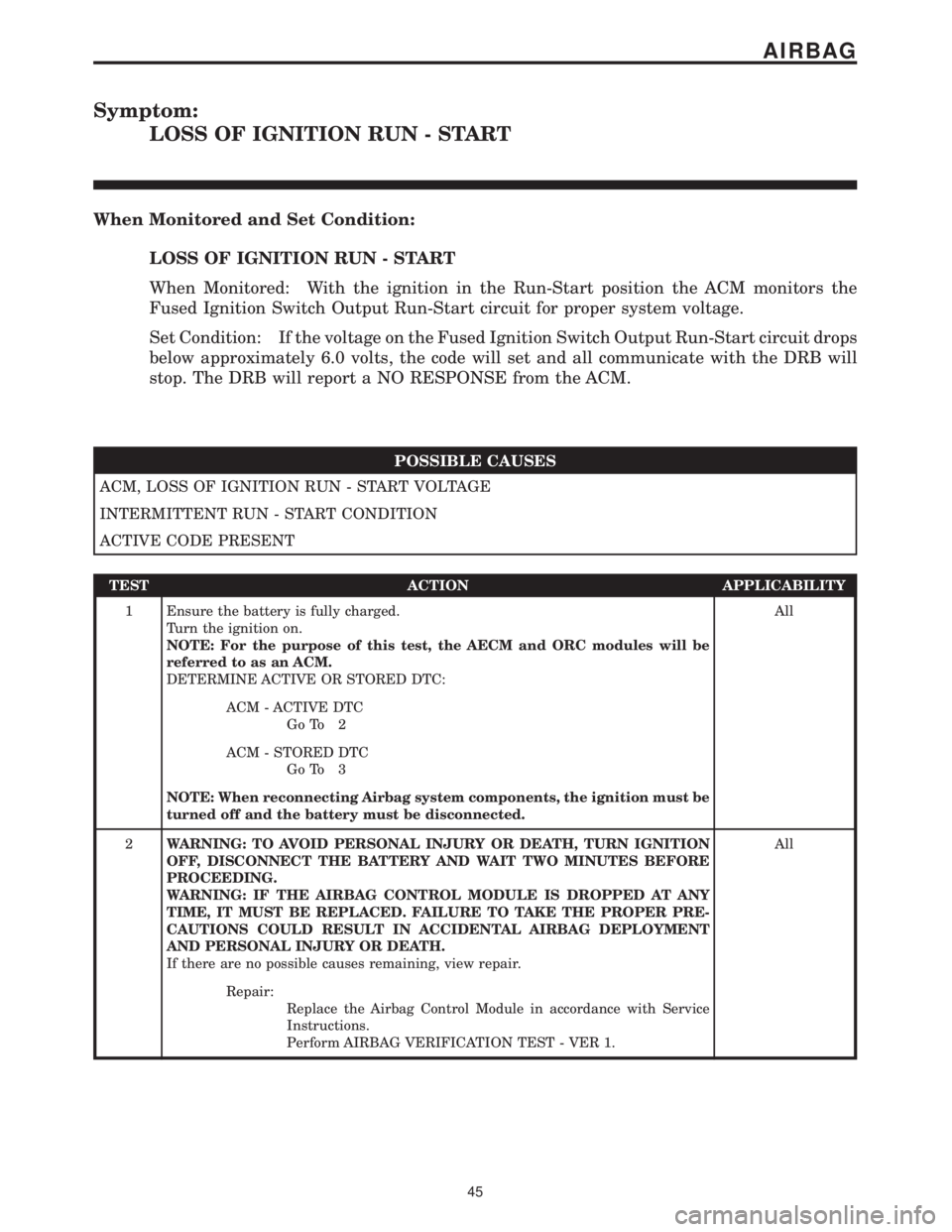
Symptom:
LOSS OF IGNITION RUN - START
When Monitored and Set Condition:
LOSS OF IGNITION RUN - START
When Monitored: With the ignition in the Run-Start position the ACM monitors the
Fused Ignition Switch Output Run-Start circuit for proper system voltage.
Set Condition: If the voltage on the Fused Ignition Switch Output Run-Start circuit drops
below approximately 6.0 volts, the code will set and all communicate with the DRB will
stop. The DRB will report a NO RESPONSE from the ACM.
POSSIBLE CAUSES
ACM, LOSS OF IGNITION RUN - START VOLTAGE
INTERMITTENT RUN - START CONDITION
ACTIVE CODE PRESENT
TEST ACTION APPLICABILITY
1 Ensure the battery is fully charged.
Turn the ignition on.
NOTE: For the purpose of this test, the AECM and ORC modules will be
referred to as an ACM.
DETERMINE ACTIVE OR STORED DTC:All
ACM - ACTIVE DTC
Go To 2
ACM - STORED DTC
Go To 3
NOTE: When reconnecting Airbag system components, the ignition must be
turned off and the battery must be disconnected.
2WARNING: TO AVOID PERSONAL INJURY OR DEATH, TURN IGNITION
OFF, DISCONNECT THE BATTERY AND WAIT TWO MINUTES BEFORE
PROCEEDING.
WARNING: IF THE AIRBAG CONTROL MODULE IS DROPPED AT ANY
TIME, IT MUST BE REPLACED. FAILURE TO TAKE THE PROPER PRE-
CAUTIONS COULD RESULT IN ACCIDENTAL AIRBAG DEPLOYMENT
AND PERSONAL INJURY OR DEATH.
If there are no possible causes remaining, view repair.All
Repair:
Replace the Airbag Control Module in accordance with Service
Instructions.
Perform AIRBAG VERIFICATION TEST - VER 1.
45
AIRBAG
Page 257 of 2305

Verification Tests
ABS VERIFICATION TEST - VER 1 APPLICABILITY
1. Turn the ignition off.
2. Connect all previously disconnected components and connectors.
3. Ensure all accessories are turned off and the battery is fully charged.
4. Ensure that the Ignition is on, and with the DRBIII, erase all Diagnostic Trouble Codes from
ALL modules. Start the engine and allow it to run for 2 minutes and fully operate the system
that was malfunctioning.
5. Turn the ignition off and wait 5 seconds. Turn the ignition on and using the DRBIII, read
DTC's from ALL modules.
6. If any Diagnostic Trouble Codes are present, return to Symptom list and troubleshoot new
or recurring symptom.
7. NOTE: If the CAB/HCU was replaced, ensure the CAB has been initialized
8. NOTE: If the SKREEM or ECM was replaced, refer to the service information for
proper programming procedures.
9. NOTE: For Sensor Circuit/Signal and Pump Motor faults, the CAB must sense all 4
wheels at 12 km/h (8 mph) before it will extinguish the ABS Indicator.
10. If there are no DTC's present after turning ignition on, road test the vehicle for at least 5
minutes. Perform several antilock braking stops.
11. CAUTION: Ensure braking capability is available before road testing.
12. Again, with the DRBIIItread DTC's. If any DTC's are present, return to Symptom list.
13. If there are no Diagnostic Trouble Codes (DTC's) present, and the customer's concern can
no longer be duplicated, the repair is complete.
Are any DTC's present or is the original concern still present?All
Ye s!Repair is not complete, refer to appropriate symptom.
No!Repair is complete.
AIRBAG VERIFICATION TEST - VER 1 APPLICABILITY
1. Remove any special tools or jumper wires and reconnect all previously disconnected
components - except the Battery.
2. WARNING: TO AVOID PERSONAL INJURY OR DEATH, TURN THE IGNITION ON,
THEN RECONNECT THE BATTERY.
3. Connect the DRBIIItto the Data Link Connector - use the most current software available.
4. Use the DRBIIItand erase the stored codes in all airbag system modules.
5. Turn the ignition off, and wait 15 seconds, then turn the ignition on.
6. Wait one minute, and read active codes and if there are none present read the stored codes.
7. Note: If equipped with Airbag On - Off switch, read the DTC's in all switch positions.
8. Note: Read the DTC's in all airbag system related modules.
9. If the DRBIIItshows any active or stored codes, return to the Symptom list and follow path
specified for that trouble code. If no active or stored codes are present, the repair is complete.
Are any DTC's present or is the original condition still present?All
YES
Repair is not complete, refer to appropriate symptom list.
NO
Repair is complete.
244
VERIFICATION TESTS
Page 260 of 2305

NAG1 TRANSMISSION VERIFICATION TEST - VER 1 APPLICABILITY
1. Reconnect any disconnected components.
2. Connect the DRBIIItto the Data Link Connector.
3. With the DRBIIIt, erase ABS DTCs.
4. With the DRBIIIt, erase ECM DTCs.
5. With the DRBIIIt, erase Transmission DTCs.
6. With the DRBIIIt, display Transmission Temperature. Start and run the engine until the
Transmission Temperature is HOT, above 43É C (110É F).
7. Check the Transmission fluid and adjust if necessary. Refer to the Service Information for the
proper Fluid Fill procedure.
8. NOTE: If internal repairs were performed and the shift quality is still poor, it may
be necessary to check the internal repair. Also check for any TSBs and/or Controller
Flash updates that may apply.
9. ROAD TEST PROCEDURE
10. Road test the vehicle. Make fifteen to twenty 1-2, 2-3, 3-4 and 4-5 upshifts.
11. Perform these shifts from a standing start to 72 km/h (45 MPH) with a constant throttle
opening of 20 to 25 degrees.
12. With speeds below 40 km/h (25 MPH), make five to eight wide open throttle kickdowns to
1st gear. Allow at least 5 seconds each in 2nd and 3rd gear between each kickdown.
13. With the DRBIIIt, read Transmission DTCs.
Were there any Diagnostic Trouble Codes set?All
Ye s!Repair is not complete, refer to appropriate symptom.
No!Repair is complete.
ROAD TEST VERIFICATION - VER-2 APPLICABILITY
1. Inspect the vehicle to ensure that all engine components are properly installed and
connected. Reassemble and reconnect components as necessary.
2. If this verification procedure is being performed after a non-DTC test, perform steps 3 and
4.
3. Check to see if the initial symptom still exists. If there are no trouble codes and the symptom
no longer exists, the repair was successful and testing is now complete.
4. If the initial or another symptom exists, the repair is not complete. Check all pertinent
Technical Service Bulletins (TSBs) and return to the Symptom List if necessary.
5. For previously read DTCs that have not been dealt with, return to the Symptom List and
follow the diagnostic path for that DTC; otherwise, continue.
6. If the Engine Control Module (ECM) has not been changed, perform steps 7 and 8, otherwise,
continue with step 9.
7. With the DRB IIIt, erase all diagnostic trouble codes (DTCs), then disconnect the DRB IIIt.
8. Turn the ignition off for at least 10 seconds.
9. If equipped with a Transfer Case Position Switch, perform step 10, otherwise, continue with
step 11.
10. With the ignition switch on, place the Transfer Case Shift Lever in each gear position,
stopping for 15 seconds in each position.
11. Ensure no DTCs remain by performing steps 12 through 15.
12. Road test the vehicle. For some of the road test, go at least 64 km/h (40 MPH). If this test
is for an A/C Relay Control Circuit, drive the vehicle for at least 5 minutes with the A/C on.
13. At some point, stop the vehicle and turn the engine off for at least 10 seconds, then restart
the engine and continue.
14. Upon completion of the road test, turn the engine off and check for DTCs with the DRB IIIt.
15. If the repaired DTC has set again, the repair is not complete. Check for any pertinent
Technical Service Bulletins (TSBs) and return to the Symptom List. If there are no DTCs, the
repair was successful and is now complete.
Are any DTCs or symptoms remaining?All
Ye s!Repair is not complete, refer to appropriate symptom.
No!Repair is complete.
247
VERIFICATION TESTS
Verification Tests ÐContinued
Page 362 of 2305

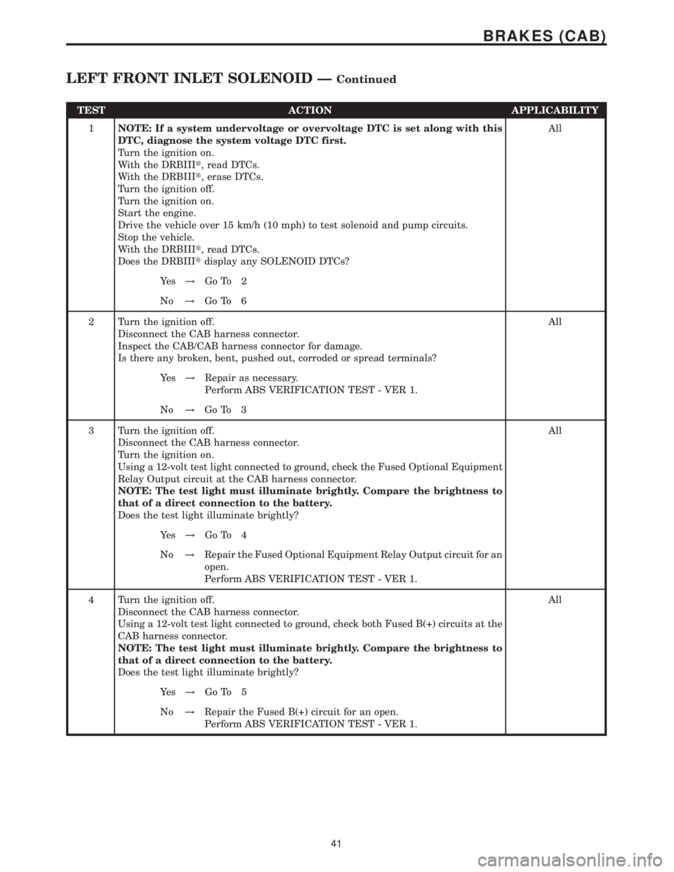
TEST ACTION APPLICABILITY
1NOTE: If a system undervoltage or overvoltage DTC is set along with this
DTC, diagnose the system voltage DTC first.
Turn the ignition on.
With the DRBIIIt, read DTCs.
With the DRBIIIt, erase DTCs.
Turn the ignition off.
Turn the ignition on.
Start the engine.
Drive the vehicle over 15 km/h (10 mph) to test solenoid and pump circuits.
Stop the vehicle.
With the DRBIIIt, read DTCs.
Does the DRBIIItdisplay any SOLENOID DTCs?All
Ye s!Go To 2
No!Go To 6
2 Turn the ignition off.
Disconnect the CAB harness connector.
Inspect the CAB/CAB harness connector for damage.
Is there any broken, bent, pushed out, corroded or spread terminals?All
Ye s!Repair as necessary.
Perform ABS VERIFICATION TEST - VER 1.
No!Go To 3
3 Turn the ignition off.
Disconnect the CAB harness connector.
Turn the ignition on.
Using a 12-volt test light connected to ground, check the Fused Optional Equipment
Relay Output circuit at the CAB harness connector.
NOTE: The test light must illuminate brightly. Compare the brightness to
that of a direct connection to the battery.
Does the test light illuminate brightly?All
Ye s!Go To 4
No!Repair the Fused Optional Equipment Relay Output circuit for an
open.
Perform ABS VERIFICATION TEST - VER 1.
4 Turn the ignition off.
Disconnect the CAB harness connector.
Using a 12-volt test light connected to ground, check both Fused B(+) circuits at the
CAB harness connector.
NOTE: The test light must illuminate brightly. Compare the brightness to
that of a direct connection to the battery.
Does the test light illuminate brightly?All
Ye s!Go To 5
No!Repair the Fused B(+) circuit for an open.
Perform ABS VERIFICATION TEST - VER 1.
41
BRAKES (CAB)
LEFT FRONT INLET SOLENOID ÐContinued
Page 367 of 2305

Symptom List:
LEFT FRONT WHEEL SPEED SENSOR SIGNAL
LEFT REAR WHEEL SPEED SENSOR SIGNAL
RIGHT FRONT WHEEL SPEED SENSOR SIGNAL
RIGHT REAR WHEEL SPEED SENSOR SIGNAL
WHEEL SPEED SENSOR SIGNAL ERROR
Test Note: All symptoms listed above are diagnosed using the same tests.
The title for the tests will be LEFT FRONT WHEEL SPEED
SENSOR SIGNAL.
When Monitored and Set Condition:
LEFT FRONT WHEEL SPEED SENSOR SIGNAL
When Monitored: Ignition On - Continuously
Set Condition: When the value of the wheel speed sensor signal is missing at vehicle
speeds over 40 km/h (25 mph) OR during a start-up test with vehicle speeds over 12km/h
(8 mph) OR the vehicle is accelerated by 18 km/h (12 mph) after a wheel speed sensor
signal has been lost.
POSSIBLE CAUSES
INTERMITTENT WHEEL SPEED SENSOR SIGNAL DTC
DAMAGED SENSOR/CAB HARNESS CONNECTOR
DAMAGED WHEEL SPEED SENSOR TONE WHEEL
EXCESSIVE WHEEL SPEED SENSOR AIR GAP
DAMAGED WHEEL BEARING
DAMAGED BRAKE LININGS/COMPONENTS
WHEEL SPEED SENSOR FAILURE
ANTI-LOCK BRAKE CONTROLLER
TEST ACTION APPLICABILITY
1NOTE: Refer to the symptom list and repair any WHEEL SPEED SENSOR
CIRCUIT DTCs before continuing.
Turn the ignition on.
With the DRBIIItin Sensors, monitor ALL the Wheel Speed Sensor signals while an
assistant drives the vehicle.
Slowly accelerate from a stop to 65 km/h (40 mph).
NOTE: Wheel Speed should not vary by more than 10% from wheel to wheel
when driving in a straight line.
Do any of the Wheel Speed Sensor signals vary by greater than 10% while driving in
a straight line?All
Ye s!Go To 2
No!Go To 8
46
BRAKES (CAB)
Page 381 of 2305

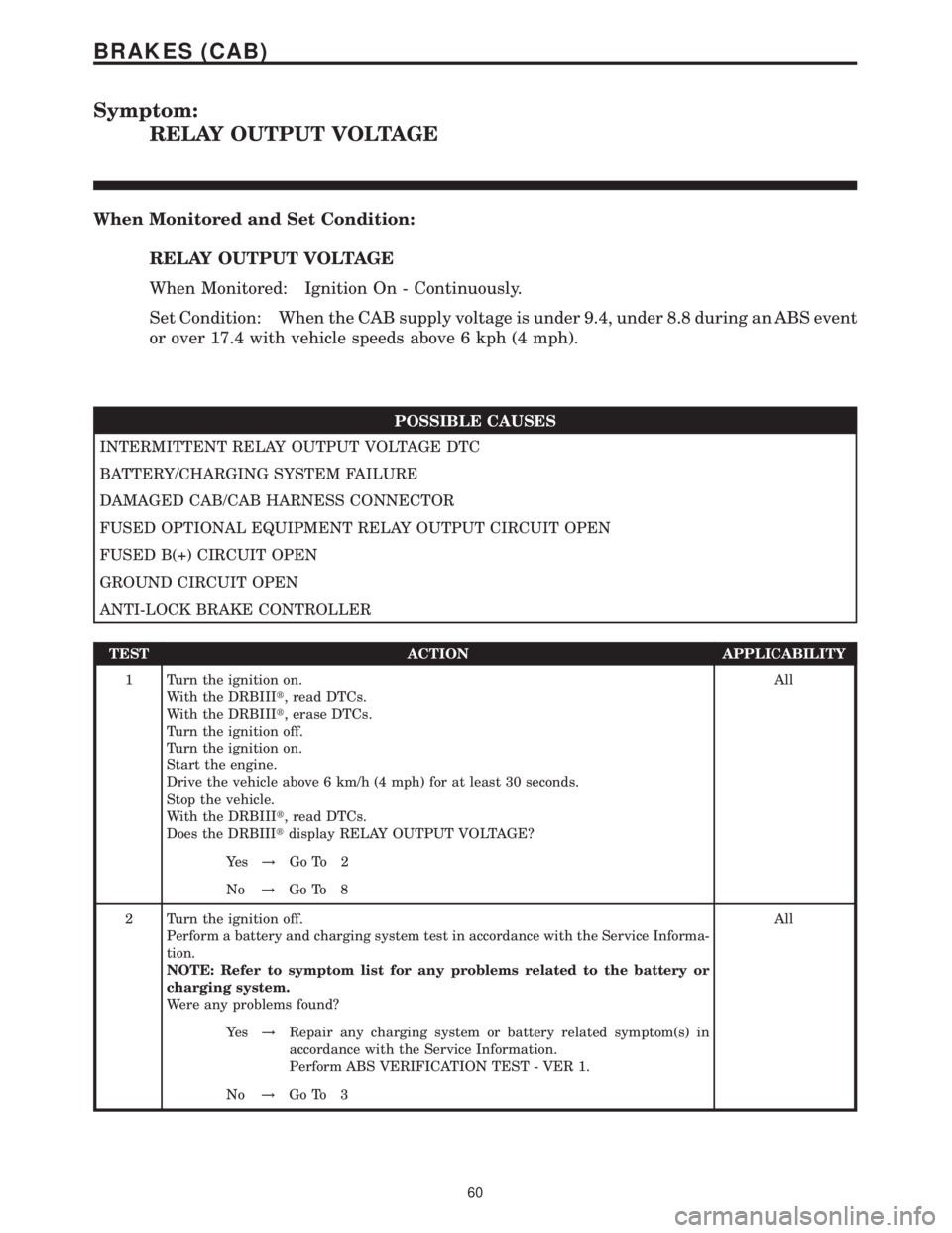
Symptom:
RELAY OUTPUT VOLTAGE
When Monitored and Set Condition:
RELAY OUTPUT VOLTAGE
When Monitored: Ignition On - Continuously.
Set Condition: When the CAB supply voltage is under 9.4, under 8.8 during an ABS event
or over 17.4 with vehicle speeds above 6 kph (4 mph).
POSSIBLE CAUSES
INTERMITTENT RELAY OUTPUT VOLTAGE DTC
BATTERY/CHARGING SYSTEM FAILURE
DAMAGED CAB/CAB HARNESS CONNECTOR
FUSED OPTIONAL EQUIPMENT RELAY OUTPUT CIRCUIT OPEN
FUSED B(+) CIRCUIT OPEN
GROUND CIRCUIT OPEN
ANTI-LOCK BRAKE CONTROLLER
TEST ACTION APPLICABILITY
1 Turn the ignition on.
With the DRBIIIt, read DTCs.
With the DRBIIIt, erase DTCs.
Turn the ignition off.
Turn the ignition on.
Start the engine.
Drive the vehicle above 6 km/h (4 mph) for at least 30 seconds.
Stop the vehicle.
With the DRBIIIt, read DTCs.
Does the DRBIIItdisplay RELAY OUTPUT VOLTAGE?All
Ye s!Go To 2
No!Go To 8
2 Turn the ignition off.
Perform a battery and charging system test in accordance with the Service Informa-
tion.
NOTE: Refer to symptom list for any problems related to the battery or
charging system.
Were any problems found?All
Ye s!Repair any charging system or battery related symptom(s) in
accordance with the Service Information.
Perform ABS VERIFICATION TEST - VER 1.
No!Go To 3
60
BRAKES (CAB)
Page 400 of 2305

Verification Tests
ABS VERIFICATION TEST - VER 1 APPLICABILITY
1. Turn the ignition off.
2. Connect all previously disconnected components and connectors.
3. Ensure all accessories are turned off and the battery is fully charged.
4. Ensure that the Ignition is on, and with the DRBIII, erase all Diagnostic Trouble Codes from
ALL modules. Start the engine and allow it to run for 2 minutes and fully operate the system
that was malfunctioning.
5. Turn the ignition off and wait 5 seconds. Turn the ignition on and using the DRBIII, read
DTC's from ALL modules.
6. If any Diagnostic Trouble Codes are present, return to Symptom list and troubleshoot new
or recurring symptom.
7. NOTE: If the CAB/HCU was replaced, ensure the CAB has been initialized
8. NOTE: If the SKREEM or ECM was replaced, refer to the service information for
proper programming procedures.
9. NOTE: For Sensor Circuit/Signal and Pump Motor faults, the CAB must sense all 4
wheels at 12 km/h (8 mph) before it will extinguish the ABS Indicator.
10. If there are no DTC's present after turning ignition on, road test the vehicle for at least 5
minutes. Perform several antilock braking stops.
11. CAUTION: Ensure braking capability is available before road testing.
12. Again, with the DRBIIItread DTC's. If any DTC's are present, return to Symptom list.
13. If there are no Diagnostic Trouble Codes (DTC's) present, and the customer's concern can
no longer be duplicated, the repair is complete.
Are any DTC's present or is the original concern still present?All
Ye s!Repair is not complete, refer to appropriate symptom.
No!Repair is complete.
79
VERIFICATION TESTS
Page 430 of 2305

small
mass air flow sensor positive deviation
mass air flow sensor signal circuit open or shorted
mass air flow sensor signal voltage too high
mass air flow sensor signal voltage too high
mass air flow sensor signal voltage too low
mass air flow sensor signal voltage too low
mass air flow sensor signal voltage too low
mass air flow sensor signal voltage too low
mass air flow sensor supply voltage too high
mass air flow sensor supply voltage too low
misfire cylinder #1
misfire cylinder #1
misfire cylinder #2
misfire cylinder #2
misfire cylinder #3
misfire cylinder #3
misfire cylinder #4
misfire cylinder #4
misfire cylinder #5
misfire cylinder #5
misfire detected
no message received from skreem
o2 circuit fault
o2 sensor circuit calibration value too high
o2 sensor circuit calibration value too high
o2 sensor circuit calibration value too high
o2 sensor circuit calibration value too low
o2 sensor circuit calibration value too low
o2 sensor circuit calibration value too low
o2 sensor circuit fault
o2 sensor circuit fault
o2 sensor circuit open circuit
o2 sensor circuit open circuit
o2 sensor circuit signal voltage too high
o2 sensor circuit signal voltage too high
o2 sensor circuit signal voltage too low
o2 sensor circuit signal voltage too low
o2 sensor heater circuit fault
o2 sensor low o2 concentration
o2 sensor plausibility
o2 sensor plausibility
o2 sensor plausibility
o2 sensor plausibility
o2 sensor plausibility
o2 sensor signal circuit signal voltage too high
o2 sensor signal circuit signal voltage too high
o2 sensor signal circuit signal voltage too high
o2 sensor signal fault
o2 sensor signal plausibility
s/c excessive acceleration
s/c excessive deceleration
s/c vehicle speed plausibility
sensor supply 1 voltage is too high
sensor supply 1 voltage is too low
sensor supply 2 voltage is too high
sensor supply 2 voltage is too low
sensor supply 3 voltage is too highsensor supply 3 voltage is too low
starter relay circuit ecm thermal overload
starter relay circuit open or shorted to voltage
starter relay circuit short circuit
starter relay circuit short to ground
steering angle sensor plausibility
tcm dtc 1-2 and 4-5 shift solenoid fault present
tcm dtc 2-3 shift solenoid fault present
tcm dtc 3-4 shift solenoid fault present
tcm dtc can msg implausible fault present
tcm dtc ewm can message fault present
tcm dtc internal fault present
tcm dtc modulating pressure solenoid fault present
tcm dtc negative gear comparison fault present
tcm dtc not unequivocal fault present
tcm dtc right rear wheel speed implausible fault
present
tcm dtc shift pressure solenoid fault present
tcm dtc speed sensor voltage fault present
tcm dtc tcc excessive power consumption fault
present
tcm dtc torque converter clutch solenoid fault
present
tcm dtc transmission ratio error fault present
tcm dtc valve voltage supply fault present
tcm message error
tcm no can message
torque reduction message from abs -can plausibility
torque reduction message from abs -message error
torque reduction message from abs -messages miss-
ing
torque reduction message from abs -no communica-
tion
torque reduction message from abs -plausibility #1
torque reduction message from abs plausibility #2
torque reduction message from hvac switch signal
plausibility
torque reduction message from hvac-parity error
torque reduction message from hvac-switch signal
error
torque reduction message from tcm -can plausibil-
ity
torque reduction message from tcm -engine stop
torque reduction message from tcm -message error
torque reduction message from tcm -messages miss-
ing
torque reduction message from tcm -plausibility
torque reduction message from tcm -tcm dtc #1
torque reduction message from tcm -tcm dtc #2
water in fuel sensor signal error
water in fuel sensor -water in fuel
wheel speed sensor plaus -can bus message from
abs
write error to eeprom
7
GENERAL INFORMATION