2006 MERCEDES-BENZ SPRINTER stop start
[x] Cancel search: stop startPage 1168 of 2305
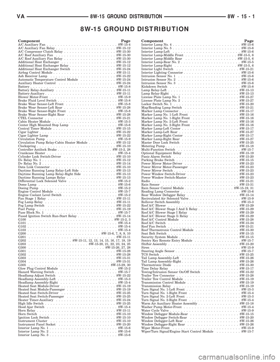
8W-15 GROUND DISTRIBUTION
Component PageA/C Auxiliary Fan..........................8W-15-4
A/C Auxiliary Fan Relay......................8W-15-12
A/C Compressor Clutch Relay...................8W-15-30
A/C Roof Auxiliary Fan......................8W-15-30
A/C Roof Auxiliary Fan Relay...................8W-15-30
Additional Heat Exchanger....................8W-15-12
Additional Heat Exchanger Relay.................8W-15-12
Additional Heat Exchanger Switch................8W-15-24
Airbag Control Module.......................8W-15-11
Ash Receiver Lamp........................8W-15-22
Automatic Temperature Control Module.............8W-15-24
Auxiliary Heater Control.....................8W-15-24
Battery................................8W-15-8
Battery Relay-Auxiliary......................8W-15-11
Battery-Auxiliary..........................8W-15-11
Blower Motor-Front.........................8W-15-9
Brake Fluid Level Switch......................8W-15-8
Brake Wear Sensor-Left Front...................8W-15-8
Brake Wear Sensor-Left Rear...................8W-15-28
Brake Wear Sensor-Right Front..................8W-15-8
Brake Wear Sensor-Right Rear..................8W-15-28
CTEL Connector..........................8W-15-21
Cabin Heater Module........................8W-15-3
Center High Mounted Stop Lamp.................8W-15-6
Central Timer Module.......................8W-15-15
Cigar Lighter............................8W-15-22
Cigar Lighter Lamp........................8W-15-22
Circulation Pump..........................8W-15-9
Circulation Pump Relay-Cabin Heater Module..........8W-15-12
Clockspring.............................8W-15-10
Controller Antilock Brake....................8W-15-2, 28
Crankcase Heater..........................8W-15-4
Cylinder Lock Switch-Driver...................8W-15-10
D+ Relay No. 1...........................8W-15-12
D+ Relay No. 2...........................8W-15-14
Data Link Connector........................8W-15-10
Daytime Running Lamp Relay-Left Side.............8W-15-13
Daytime Running Lamp Relay-Right Side............8W-15-13
Daytime Running Lamps Relay..................8W-15-13
Differential Lock Solenoid Valve..................8W-15-2
Dome Lamp.............................8W-15-6
Dosing Pump............................8W-15-2
Engine Control Module.......................8W-15-7
Engine Coolant Level Switch....................8W-15-2
Fan Stage 1 Relay.........................8W-15-11
Fog Lamp Relay..........................8W-15-11
Fog Lamp Switch.........................8W-15-22
Fuel Pump.............................8W-15-19
Fuse Block No. 1..........................8W-15-7
Fused Ignition Switch Run-Start Relay..............8W-15-14
G100...............................8W-15-2, 3
G101.................................8W-15-4
G102.................................8W-15-4
G103.................................8W-15-4
G200...........................8W-15-6, 7, 8, 9, 10
G201................................8W-15-11
G202................8W-15-11, 12, 13, 14, 15, 16, 17, 18, 19
G203......................8W-15-20, 21, 22, 23, 24, 25
G300............................8W-15-26, 27, 28
G301................................8W-15-28
G302................................8W-15-28
G303................................8W-15-31
G304................................8W-15-31
G305..............................8W-15-29, 30
Glow Plug Control Module.....................8W-15-2
Hazard Warning Switch.......................8W-15-7
Headlamp Adjust Switch.....................8W-15-22
Headlamp Assembly-Left......................8W-15-3
Headlamp Assembly-Right.....................8W-15-4
Heated Seat Module-Driver....................8W-15-19
Heated Seat Module-Passenger..................8W-15-19
Heated Seat Switch-Driver....................8W-15-25
Heated Seat Switch-Passenger..................8W-15-25
Heater Timer-Auxiliary......................8W-15-24
High Idle Switch..........................8W-15-25
Hood Ajar Switch..........................8W-15-4
Horn Relay.............................8W-15-11
Horn Switch............................8W-15-10
Ignition Lock Switch........................8W-15-10
Instrument Cluster........................8W-15-10
Instrument Panel Socket.....................8W-15-20
Interior Lamp No. 1.........................8W-15-6
Interior Lamp No. 2.........................8W-15-6
Interior Lamp No. 3.........................8W-15-6Component PageInterior Lamp No. 4.........................8W-15-6
Interior Lamp No. 5.........................8W-15-6
Interior Lamp-Left.........................8W-15-6
Interior Lamp-Middle Front...................8W-15-5, 6
Interior Lamp-Middle Rear...................8W-15-5, 6
Interior Lamp-Rear No. 2......................8W-15-5
Interior Lamp-Right.......................8W-15-5, 6
Interior Light Switch.......................8W-15-21
Interior Lighting Connector.....................8W-15-6
Intrusion Sensor No. 1.......................8W-15-6
Intrusion Sensor No. 2.......................8W-15-6
Intrusion Sensor No. 3.......................8W-15-6
Kickdown Switch..........................8W-15-8
Lamp Relay-Left..........................8W-15-13
Lamp Relay-Right.........................8W-15-13
License Plate Lamp No. 1.....................8W-15-27
License Plate Lamp No. 2.....................8W-15-27
Locker Switch No. 1........................8W-15-20
Map/Reading Lamp Switch....................8W-15-21
Marker Lamp Connector......................8W-15-17
Marker Lamp No. 1-Left Front..................8W-15-16
Marker Lamp No. 1-Right Front.................8W-15-16
Marker Lamp No. 2-Left Front..................8W-15-16
Marker Lamp No. 2-Right Front.................8W-15-16
Marker Lamp-Left Center.....................8W-15-17
Marker Lamp-Left Rear......................8W-15-27
Marker Lamp-Right Center....................8W-15-17
Marker Lamp-Right Rear.....................8W-15-27
Master Door Lock Switch.....................8W-15-25
Metering Pump...........................8W-15-18
Multi-Function Switch.......................8W-15-7
Optional Equipment Relay....................8W-15-19
Panic Alarm Switch........................8W-15-20
Parking Brake Switch.......................8W-15-15
Power Mirror Motor-Driver....................8W-15-23
Power Mirror Motor-Passenger..................8W-15-23
Power Mirror Switch........................8W-15-23
Power Window Switch-Driver...................8W-15-23
Power Window Switch-Master...................8W-15-23
Radio................................8W-15-21
Rain Sensor............................8W-15-31
Rain Sensor Control Module..................8W-15-19, 31
Reading Lamp Connector......................8W-15-6
Rear Window Defogger Relay...................8W-15-14
Recirculated Air Solenoid Valve...................8W-15-9
Rollover Switch Assembly......................8W-15-3
Roof A/C Blower..........................8W-15-29
Roof A/C Blower Stage I And Ii Relay...............8W-15-29
Roof A/C Blower Stage I Relay..................8W-15-29
Roof A/C Blower Stage Ii Relay..................8W-15-29
Roof A/C Control Module.....................8W-15-28
Roof A/C Switch..........................8W-15-24
Roof Fan Switch..........................8W-15-21
Roof Thermotronic Control Module................8W-15-30
Seat Belt Switch..........................8W-15-15
Security System Module......................8W-15-15
Sentry Key Remote Entry Module.................8W-15-7
Shifter Assembly..........................8W-15-20
Siren.................................8W-15-9
Steering Angle Sensor........................8W-15-7
TCS Switch.............................8W-15-25
Tail Lamp Assembly-Left.....................8W-15-26
Tail Lamp Assembly-Right.....................8W-15-26
Thermotronic Diode........................8W-15-30
Time Delay Relay.........................8W-15-17
Towing/Intrusion Sensor On/Off Switch..............8W-15-22
Trailer Tow Connector.......................8W-15-28
Trailer Tow Control Module....................8W-15-19
Transmission Control Module...................8W-15-19
Transmission Relay........................8W-15-19
Turn Signal No. 1-Left Front....................8W-15-3
Turn Signal No. 1-Right Front...................8W-15-4
Turn Signal No. 2-Left Front....................8W-15-3
Turn Signal No. 2-Right Front...................8W-15-4
Warm Air Auxiliary Heater Assembly...............8W-15-18
Washer Pump Motor-Front.....................8W-15-4
Water Cycle Valve..........................8W-15-9
Window Defogger Module-Rear..................8W-15-15
Window Defogger Switch-Rear..................8W-15-20
Window Defogger-Left Rear....................8W-15-26
Window Defogger-Right Rear...................8W-15-26
Wiper Motor-Front.........................8W-15-9
Wiper/Turn Signal/Engine Start Control Module.........8W-15-7
VA8W-15 GROUND DISTRIBUTION 8W - 15 - 1
Page 1446 of 2305
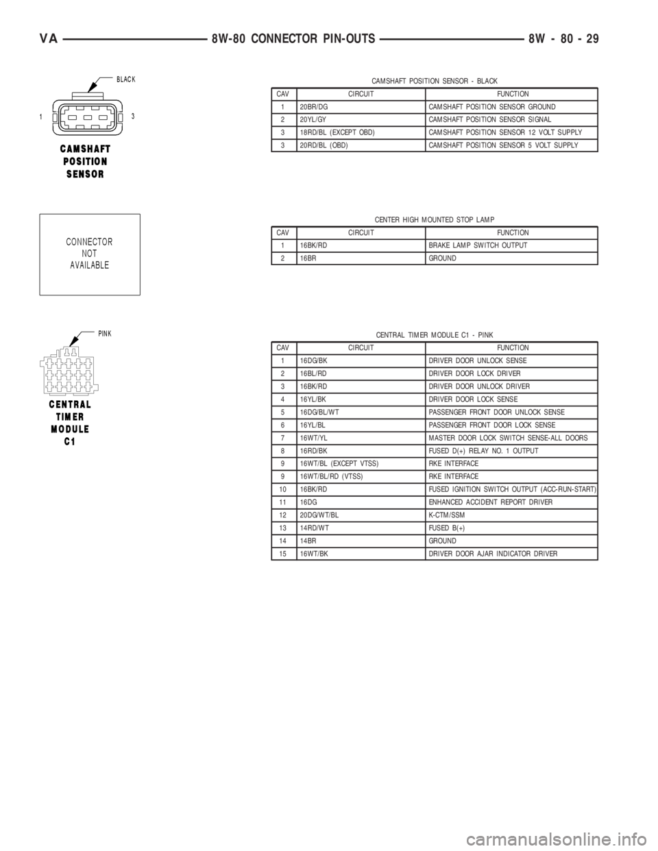
CAMSHAFT POSITION SENSOR - BLACK
CAV CIRCUIT FUNCTION
1 20BR/DG CAMSHAFT POSITION SENSOR GROUND
2 20YL/GY CAMSHAFT POSITION SENSOR SIGNAL
3 18RD/BL (EXCEPT OBD) CAMSHAFT POSITION SENSOR 12 VOLT SUPPLY
3 20RD/BL (OBD) CAMSHAFT POSITION SENSOR 5 VOLT SUPPLY
CENTER HIGH MOUNTED STOP LAMP
CAV CIRCUIT FUNCTION
1 16BK/RD BRAKE LAMP SWITCH OUTPUT
2 16BR GROUND
CENTRAL TIMER MODULE C1 - PINK
CAV CIRCUIT FUNCTION
1 16DG/BK DRIVER DOOR UNLOCK SENSE
2 16BL/RD DRIVER DOOR LOCK DRIVER
3 16BK/RD DRIVER DOOR UNLOCK DRIVER
4 16YL/BK DRIVER DOOR LOCK SENSE
5 16DG/BL/WT PASSENGER FRONT DOOR UNLOCK SENSE
6 16YL/BL PASSENGER FRONT DOOR LOCK SENSE
7 16WT/YL MASTER DOOR LOCK SWITCH SENSE-ALL DOORS
8 16RD/BK FUSED D(+) RELAY NO. 1 OUTPUT
9 16WT/BL (EXCEPT VTSS) RKE INTERFACE
9 16WT/BL/RD (VTSS) RKE INTERFACE
10 16BK/RD FUSED IGNITION SWITCH OUTPUT (ACC-RUN-START)
11 16DG ENHANCED ACCIDENT REPORT DRIVER
12 20DG/WT/BL K-CTM/SSM
13 14RD/WT FUSED B(+)
14 14BR GROUND
15 16WT/BK DRIVER DOOR AJAR INDICATOR DRIVER
VA8W-80 CONNECTOR PIN-OUTS 8W - 80 - 29
Page 1630 of 2305
REMOVAL
(1) Disconnect negative battery cable.
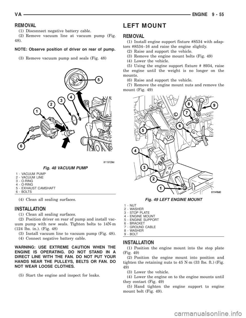
(2) Remove vacuum line at vacuum pump (Fig.
48).
NOTE: Observe position of driver on rear of pump.
(3) Remove vacuum pump and seals (Fig. 48)
(4) Clean all sealing surfaces.
INSTALLATION
(1) Clean all sealing surfaces.
(2) Position driver on rear of pump and install vac-
uum pump with new seals. Tighten bolts to 14N´m
(124 lbs. in.). (Fig. 48)
(3) Install vacuum line to vacuum pump (Fig. 48).
(4) Connect negative battery cable.
WARNING: USE EXTREME CAUTION WHEN THE
ENGINE IS OPERATING. DO NOT STAND IN A
DIRECT LINE WITH THE FAN. DO NOT PUT YOUR
HANDS NEAR THE PULLEYS, BELTS OR FAN. DO
NOT WEAR LOOSE CLOTHES.
(5) Start the engine and inspect for leaks.
LEFT MOUNT
REMOVAL
(1) Install engine support fixture #8534 with adap-
tors #8534±16 and raise the engine slightly.
(2) Raise and support the vehicle.
(3) Remove the engine mount bolts (Fig. 49)
(4) Lower the vehicle.
(5) Using the engine support fixture # 8934, raise
the engine until the weight is no longer on the
mounts.
(6) Raise and support the vehicle.
(7) Remove the engine mount nuts and remove the
mount (Fig. 49)
INSTALLATION
(1) Position the engine mount into the stop plate
(Fig. 49)
(2) Position the engine mount into position and
tighten the retaining nuts to 45 N´m (33 lbs. ft.) (Fig.
49)
(3) Lower the vehicle.
(4) Lower the engine on to the engine mounts until
they contact (Fig. 49)
(5) Hand tighten the engine support to engine
mount bolt (Fig. 49).
Fig. 48 VACUUM PUMP
1 - VACUUM PUMP
2 - VACUUM LINE
3 - O-RING
4 - O-RING
5 - EXHAUST CAMSHAFT
6 - BOLTS
Fig. 49 LEFT ENGINE MOUNT
1 - NUT
2 - WASHER
3 - STOP PLATE
4 - ENGINE MOUNT
5 - ENGINE SUPPORT
6 - BRACKET
7 - GROUND CABLE
8 - WASHER
9 - BOLT
VAENGINE 9 - 55
Page 1639 of 2305
(14) Remove riveting tool.
(15) Turn over tool moving assembly insert to the
riveting profile.
NOTE: Rivet pins of the riveted link individually.
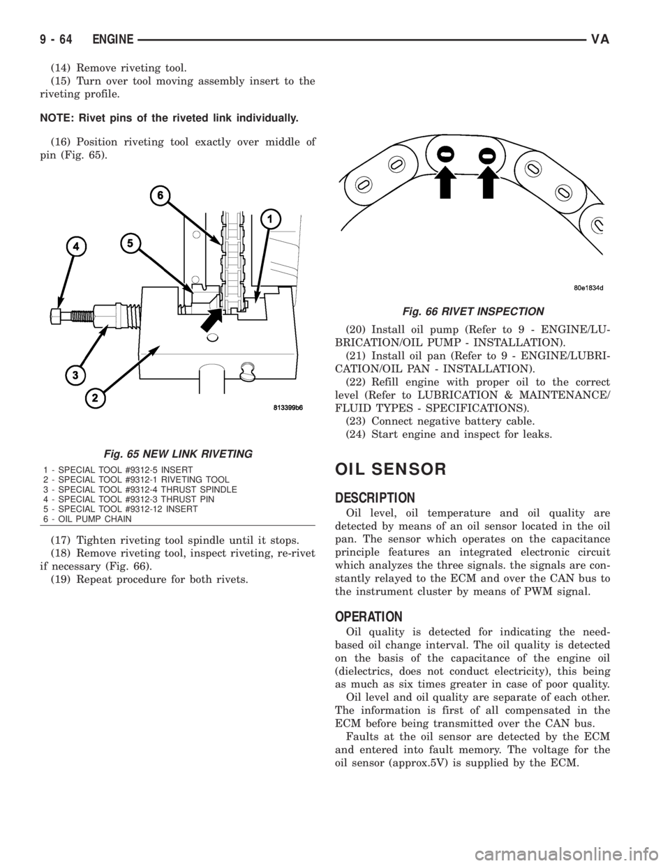
(16) Position riveting tool exactly over middle of
pin (Fig. 65).
(17) Tighten riveting tool spindle until it stops.
(18) Remove riveting tool, inspect riveting, re-rivet
if necessary (Fig. 66).
(19) Repeat procedure for both rivets.(20) Install oil pump (Refer to 9 - ENGINE/LU-
BRICATION/OIL PUMP - INSTALLATION).
(21) Install oil pan (Refer to 9 - ENGINE/LUBRI-
CATION/OIL PAN - INSTALLATION).
(22) Refill engine with proper oil to the correct
level (Refer to LUBRICATION & MAINTENANCE/
FLUID TYPES - SPECIFICATIONS).
(23) Connect negative battery cable.
(24) Start engine and inspect for leaks.
OIL SENSOR
DESCRIPTION
Oil level, oil temperature and oil quality are
detected by means of an oil sensor located in the oil
pan. The sensor which operates on the capacitance
principle features an integrated electronic circuit
which analyzes the three signals. the signals are con-
stantly relayed to the ECM and over the CAN bus to
the instrument cluster by means of PWM signal.
OPERATION
Oil quality is detected for indicating the need-
based oil change interval. The oil quality is detected
on the basis of the capacitance of the engine oil
(dielectrics, does not conduct electricity), this being
as much as six times greater in case of poor quality.
Oil level and oil quality are separate of each other.
The information is first of all compensated in the
ECM before being transmitted over the CAN bus.
Faults at the oil sensor are detected by the ECM
and entered into fault memory. The voltage for the
oil sensor (approx.5V) is supplied by the ECM.
Fig. 65 NEW LINK RIVETING
1 - SPECIAL TOOL #9312-5 INSERT
2 - SPECIAL TOOL #9312-1 RIVETING TOOL
3 - SPECIAL TOOL #9312-4 THRUST SPINDLE
4 - SPECIAL TOOL #9312-3 THRUST PIN
5 - SPECIAL TOOL #9312-12 INSERT
6 - OIL PUMP CHAIN
Fig. 66 RIVET INSPECTION
9 - 64 ENGINEVA
Page 1716 of 2305
(3) Install engine cover.
(4) Reconnect negative battery cable.
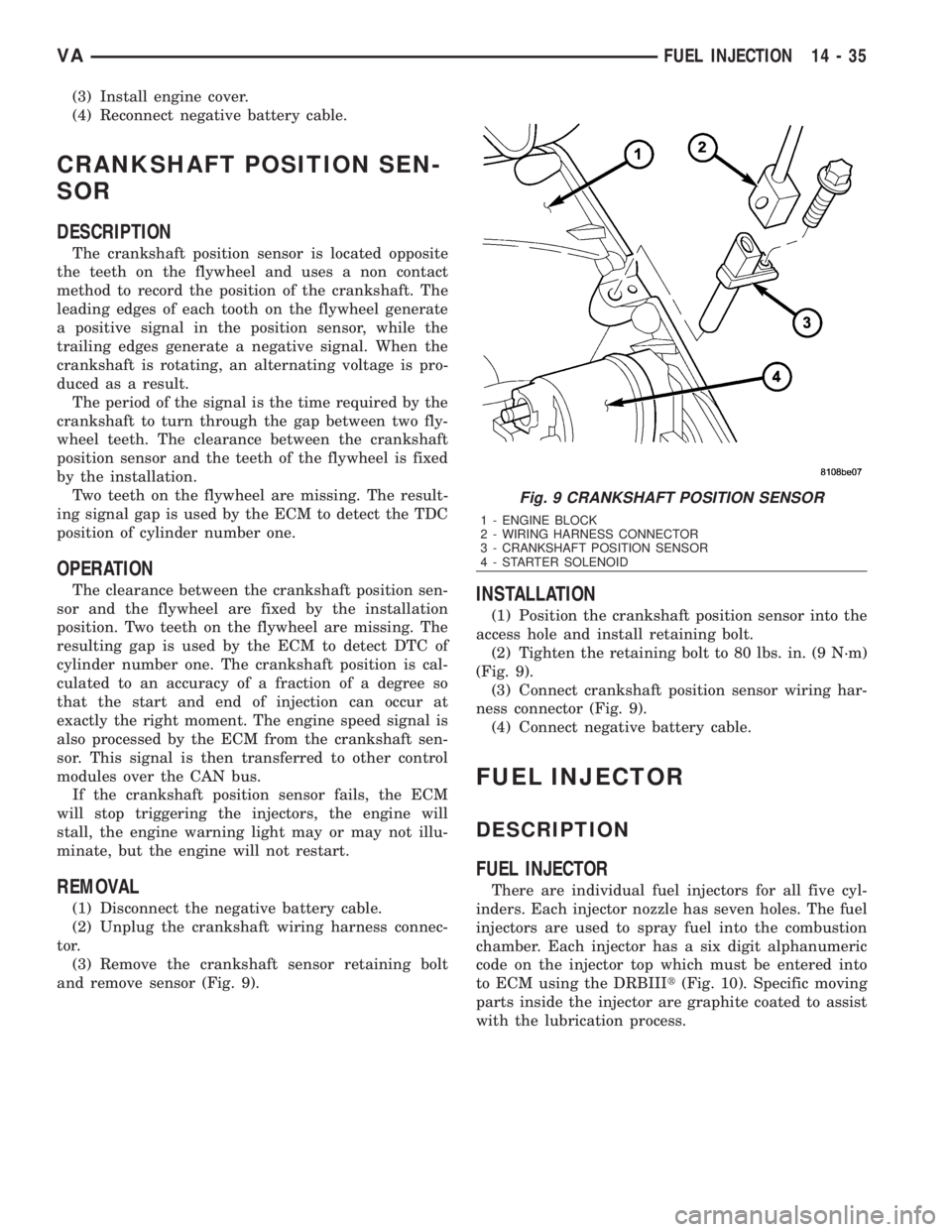
CRANKSHAFT POSITION SEN-
SOR
DESCRIPTION
The crankshaft position sensor is located opposite
the teeth on the flywheel and uses a non contact
method to record the position of the crankshaft. The
leading edges of each tooth on the flywheel generate
a positive signal in the position sensor, while the
trailing edges generate a negative signal. When the
crankshaft is rotating, an alternating voltage is pro-
duced as a result.
The period of the signal is the time required by the
crankshaft to turn through the gap between two fly-
wheel teeth. The clearance between the crankshaft
position sensor and the teeth of the flywheel is fixed
by the installation.
Two teeth on the flywheel are missing. The result-
ing signal gap is used by the ECM to detect the TDC
position of cylinder number one.
OPERATION
The clearance between the crankshaft position sen-
sor and the flywheel are fixed by the installation
position. Two teeth on the flywheel are missing. The
resulting gap is used by the ECM to detect DTC of
cylinder number one. The crankshaft position is cal-
culated to an accuracy of a fraction of a degree so
that the start and end of injection can occur at
exactly the right moment. The engine speed signal is
also processed by the ECM from the crankshaft sen-
sor. This signal is then transferred to other control
modules over the CAN bus.
If the crankshaft position sensor fails, the ECM
will stop triggering the injectors, the engine will
stall, the engine warning light may or may not illu-
minate, but the engine will not restart.
REMOVAL
(1) Disconnect the negative battery cable.
(2) Unplug the crankshaft wiring harness connec-
tor.
(3) Remove the crankshaft sensor retaining bolt
and remove sensor (Fig. 9).
INSTALLATION
(1) Position the crankshaft position sensor into the
access hole and install retaining bolt.
(2) Tighten the retaining bolt to 80 lbs. in. (9 N´m)
(Fig. 9).
(3) Connect crankshaft position sensor wiring har-
ness connector (Fig. 9).
(4) Connect negative battery cable.
FUEL INJECTOR
DESCRIPTION
FUEL INJECTOR
There are individual fuel injectors for all five cyl-
inders. Each injector nozzle has seven holes. The fuel
injectors are used to spray fuel into the combustion
chamber. Each injector has a six digit alphanumeric
code on the injector top which must be entered into
to ECM using the DRBIIIt(Fig. 10). Specific moving
parts inside the injector are graphite coated to assist
with the lubrication process.
Fig. 9 CRANKSHAFT POSITION SENSOR
1 - ENGINE BLOCK
2 - WIRING HARNESS CONNECTOR
3 - CRANKSHAFT POSITION SENSOR
4 - STARTER SOLENOID
VAFUEL INJECTION 14 - 35
Page 1718 of 2305
position against the opening forces applied to its
pressure stage (Fig. 11).
Injector opens (start of injection)
The solenoid valve is energized with the pickup
current which serves to ensure that it open quickly.
The force exerted by the triggered solenoid now
exceeds that of the valve spring and the armature
opens the bleed orifice. Almost immediately, the high-
level pick-up current is reduced to the lower holding
current required for the electromagnet. This is possi-
ble due to the magnetic circuit's air gap now being
smaller. When the bleed orifice opens, fuel can flow
from the valve control chamber into the cavity situ-
ated above it, and from there via the fuel return to
the tank. The bleed orifice prevents complete pres-
sure balance, and the pressure in the valve control
chamber sinks as a result. This leads to the pressure
in the valve-control chamber being lower than that in
the nozzle's chamber volume which is still at the
same pressure level as the rail. The reduced pressure
in the valve-control chamber causes a reduction in
the force exerted on the control plunger, the nozzle
needle open as a result, and injection starts (Fig. 11).
Injector opens fully
The control plunger reaches its upper stop where it
remains supported by a cushion of fuel which is gen-
erated by the flow of fuel between the bleed and feed
orifices. The injector nozzle has now opened fully,
and the fuel is injected into the combustion chamber
at a pressure almost equal to that in the fuel rail
(Fig. 11).
Injector closes (end of injection)
As soon as the solenoid valve is no longer trig-
gered, the valve spring forces the armature down-
wards and the ball closes the bleed orifice. The
armature is a 2±piece design. Here, although the
armature plate is guided by a driver shoulder in its
downward movement, it can ªoverspringº with the
return spring so that it exerts no downwards-acting
forces on the armature and the ball. The closing of
the bleed orifice lead to pressure build up in the con-
trol chamber via the input from the feed orifice. This
pressure is the same as that in the rail and exerts an
increased force on the control plunger through its
end face. This force, together with that of the spring,
now exceeds the force exerted by the chamber volume
and the nozzle needle closes. Injection ceases as soon
as the nozzle needle comes up against its bottom stop
again (Fig. 11).
STANDARD PROCEDURE
STANDARD PROCEDURE - INJECTOR CLASSI-
FICATION
NOTE: Fuel Injectors have different flow rates.
When ALL injectors are removed, re-enter all injec-
tor six digit codes.
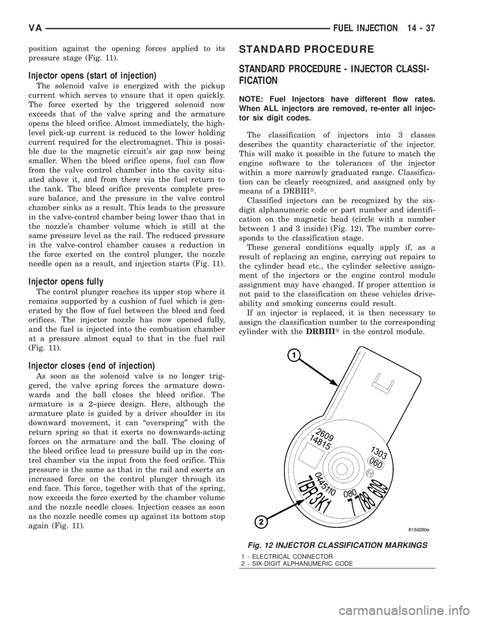
The classification of injectors into 3 classes
describes the quantity characteristic of the injector.
This will make it possible in the future to match the
engine software to the tolerances of the injector
within a more narrowly graduated range. Classifica-
tion can be clearly recognized, and assigned only by
means of a DRBIIIt.
Classified injectors can be recognized by the six-
digit alphanumeric code or part number and identifi-
cation on the magnetic head (circle with a number
between 1 and 3 inside) (Fig. 12). The number corre-
sponds to the classification stage.
These general conditions equally apply if, as a
result of replacing an engine, carrying out repairs to
the cylinder head etc., the cylinder selective assign-
ment of the injectors or the engine control module
assignment may have changed. If proper attention is
not paid to the classification on these vehicles drive-
ability and smoking concerns could result.
If an injector is replaced, it is then necessary to
assign the classification number to the corresponding
cylinder with theDRBIIItin the control module.
Fig. 12 INJECTOR CLASSIFICATION MARKINGS
1 - ELECTRICAL CONNECTOR
2 - SIX-DIGIT ALPHANUMERIC CODE
VAFUEL INJECTION 14 - 37
Page 1741 of 2305
(4) Slowly turn the steering wheel lock-to-lock 20
times with the engine off while checking the fluid
level.
NOTE: For vehicles with long return lines or oil
coolers turn wheel 40 times.
(5) Start the engine. With the engine idling main-
tain the fluid level.
(6) Lower the front wheels and let the engine idle
for two minutes.
(7) Turn the steering wheel in both direction and
verify power assist and quiet operation of the pump.
If the fluid is extremely foamy or milky looking,
allow the vehicle to stand a few minutes and repeat
the procedure.
CAUTION: Do not run a vehicle with foamy fluid for
an extended period. This may cause pump damage.
STANDARD PROCEDURE - FLUSHING POWER
STEERING SYSTEM
Flushing is required when the power steering/hy-
draulic booster system fluid has become contami-
nated. Contaminated fluid in the steering/booster
system can cause seal deterioration and affect steer-
ing gear/booster spool valve operation.
(1) Raise the front end of the vehicle off the
ground until the wheels are free to turn.
(2) Remove the return line from the pump.
NOTE: If vehicle is equipped with a hydraulic
booster remove both return lines from the pump.
(3) Plug the return line port/ports at the pump.
(4) Position the return line/lines into a large con-
tainer to catch the fluid.
(5) While an assistant is filling the pump reservoir
start the engine.
(6) With the engine running at idle turn the wheel
back and forth.
NOTE: Do not contact or hold the wheel against the
steering stops.
(7) Run a quart of fluid through the system then
stop the engine and install the return line/lines.
(8) Fill the system with fluid and perform Steering
Pump Initial Operation, (Refer to 19 - STEERING/
PUMP - STANDARD PROCEDURE).
(9) Start the engine and run it for fifteen minutes
then stop the engine.
(10) Remove the return line/lines from the pump
and plug the pump port/ports.
(11) Pour fresh fluid into the reservoir and check
the draining fluid for contamination. If the fluid is
still contaminated, then flush the system again.(12) Install the return line/lines and perform
Steering Pump Initial Operation, (Refer to 19 -
STEERING/PUMP - STANDARD PROCEDURE).
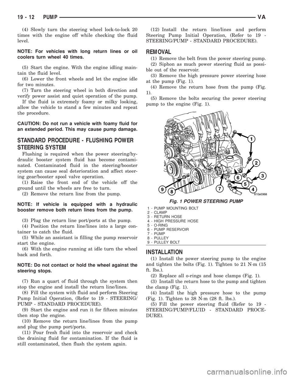
REMOVAL
(1) Remove the belt from the power steering pump.
(2) Siphon as much power steering fluid as possi-
ble out of the reservoir.
(3) Remove the high pressure power steering hose
at the pump (Fig. 1).
(4) Remove the return hose from the pump (Fig.
1).
(5) Remove the bolts securing the power steering
pump to the engine (Fig. 1).
INSTALLATION
(1) Install the power steering pump to the engine
and tighten the bolts (Fig. 1). Tighten to 21 N´m (15
ft. lbs.).
(2) Replace all o-rings and hose clamps (Fig. 1).
(3) Install the return hose to the pump and tighten
the clamp (Fig. 1).
(4) Install the high pressure hose to the pump
(Fig. 1). Tighten to 38 N´m (28 ft. lbs.).
(5) Fill the power steering fluid (Refer to 19 -
STEERING/PUMP/FLUID - STANDARD PROCE-
DURE).
Fig. 1 POWER STEERING PUMP
1 - PUMP MOUNTING BOLT
2 - CLAMP
3 - RETURN HOSE
4 - HIGH PRESSURE HOSE
5 - O-RING
6 - PUMP RESERVOIR
7 - PUMP
8 - PULLEY
9 - PULLEY BOLT
19 - 12 PUMPVA
Page 1748 of 2305
flexible adaptation to different vehicle and engine
variants.
EMERGENCY RUNNING FUNCTION
In order to ensure a safe driving state and to pre-
vent damage to the automatic transmission, the TCM
control module switches to limp-home mode in the
event of critical faults. A diagnostic trouble code
(DTC) assigned to the fault is stored in memory. All
solenoid and regulating valves are thus de-energized.
The net effect is:
²The last engaged gear remains engaged.
²The modulating pressure and shift pressures
rise to the maximum levels.
²The torque converter lockup clutch is deacti-
vated.
In order to preserve the operability of the vehicle
to some extent, the hydraulic control can be used to
engage 2nd gear or reverse using the following pro-
cedure:²Stop the vehicle.
²Move selector lever to ªPº.
²Switch off engine.
²Wait at least 10 seconds.
²Start engine.
²Move selector lever to D: 2nd gear.
²Move selector lever to R: Reverse gear.
The limp-home function remains active until the
DTC is rectified or the stored DTC is erased with the
appropriate scan tool. Sporadic faults can be reset
via ignition OFF/ON.
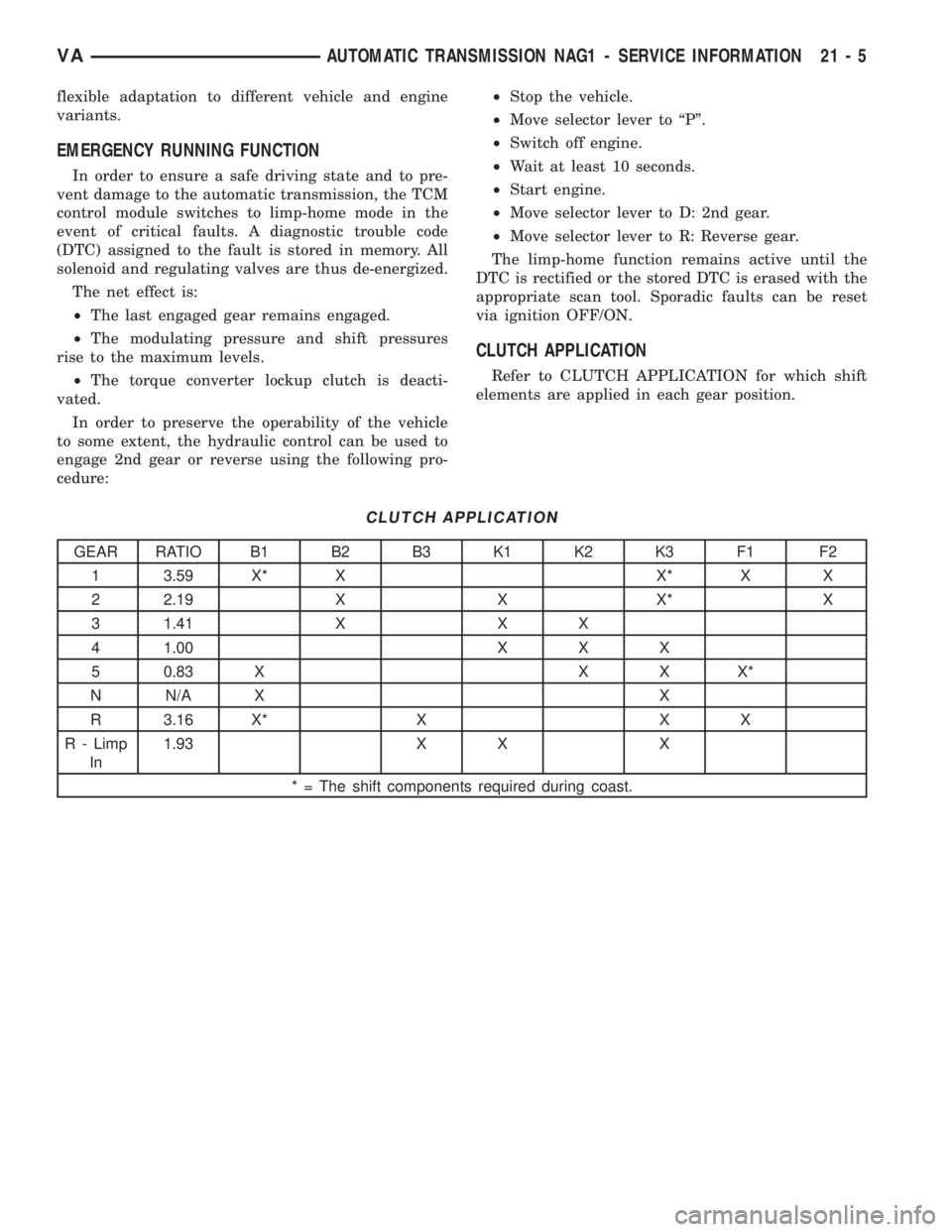
CLUTCH APPLICATION
Refer to CLUTCH APPLICATION for which shift
elements are applied in each gear position.
CLUTCH APPLICATION
GEAR RATIO B1 B2 B3 K1 K2 K3 F1 F2
1 3.59 X* X X* X X
2 2.19 X X X* X
3 1.41 X X X
4 1.00 X X X
5 0.83 X X X X*
N N/A X X
R 3.16 X* X X X
R - Limp
In1.93 X X X
* = The shift components required during coast.
VAAUTOMATIC TRANSMISSION NAG1 - SERVICE INFORMATION 21 - 5