2006 MERCEDES-BENZ SPRINTER lug pattern
[x] Cancel search: lug patternPage 663 of 2305

TEST ACTION APPLICABILITY
4NOTE: Prior to performing this test, be sure to check the Glow Plug Relay
operation. Refer to CHECKING GLOW PLUG OPERATION for the related
symptom(s).
Refer to the Service Information and check the Glow Plugs for proper operation.
Are the Glow Plugs operating properly?All
Ye s!Go To 5
No!Repair as necessary.
Perform NO START VERIFICATION - VER-1.
5 Inspect the fuel system lines for restrictions, leaks or other problems.
NOTE: Refer to the Service Information to ensure that the fuel system is
properly primed. An unprimed system or excessive air in the supply system
will cause a no-start condition.
Is there any evidence of problems?All
Ye s!Repair as necessary.
Perform NO START VERIFICATION - VER-1.
No!Go To 6
6 Refer to the Service Information and perform the fuel pressure test.
Is the fuel pressure within specification?All
Ye s!Go To 7
No!Repair as necessary.
Perform NO START VERIFICATION - VER-1.
7 Inspect the fuel supply for contamination.
Is the fuel contaminated?All
Ye s!Refer to the Service Information to remove and replace fuel
throughout the fuel system.
Perform NO START VERIFICATION - VER-1.
No!Go To 8
8 Turn the ignition off.
Using the DRBIIItlab scope, backprobe the CMP Sensor Signal circuit at the ECM
harness connector.
Start the engine, if the engine will not start, crank the engine for several seconds
while monitoring the DRBIIIt.
NOTE: Refer to Charts and Graphs to view a correct CMP Sensor signal.
Does the DRBIIItdisplay a steady clean CMP Signal pattern?All
Ye s!Go To 9
No!Perform Test for DTC P2043-Camshaft Position Sensor Circuit
Static Plausibility.
Perform NO START VERIFICATION - VER-1.
240
DRIVEABILITY - DIESEL
*ENGINE CRANKS BUT WILL NOT START ÐContinued
Page 1053 of 2305

CAUTION: Never use compressed air to flush the
washer system plumbing. Compressed air pres-
sures are too great for the washer system plumbing
components and will result in further system dam-
age. Never use sharp instruments to clear a
plugged washer nozzle or damage to the nozzle ori-
fice and improper nozzle spray patterns will result.
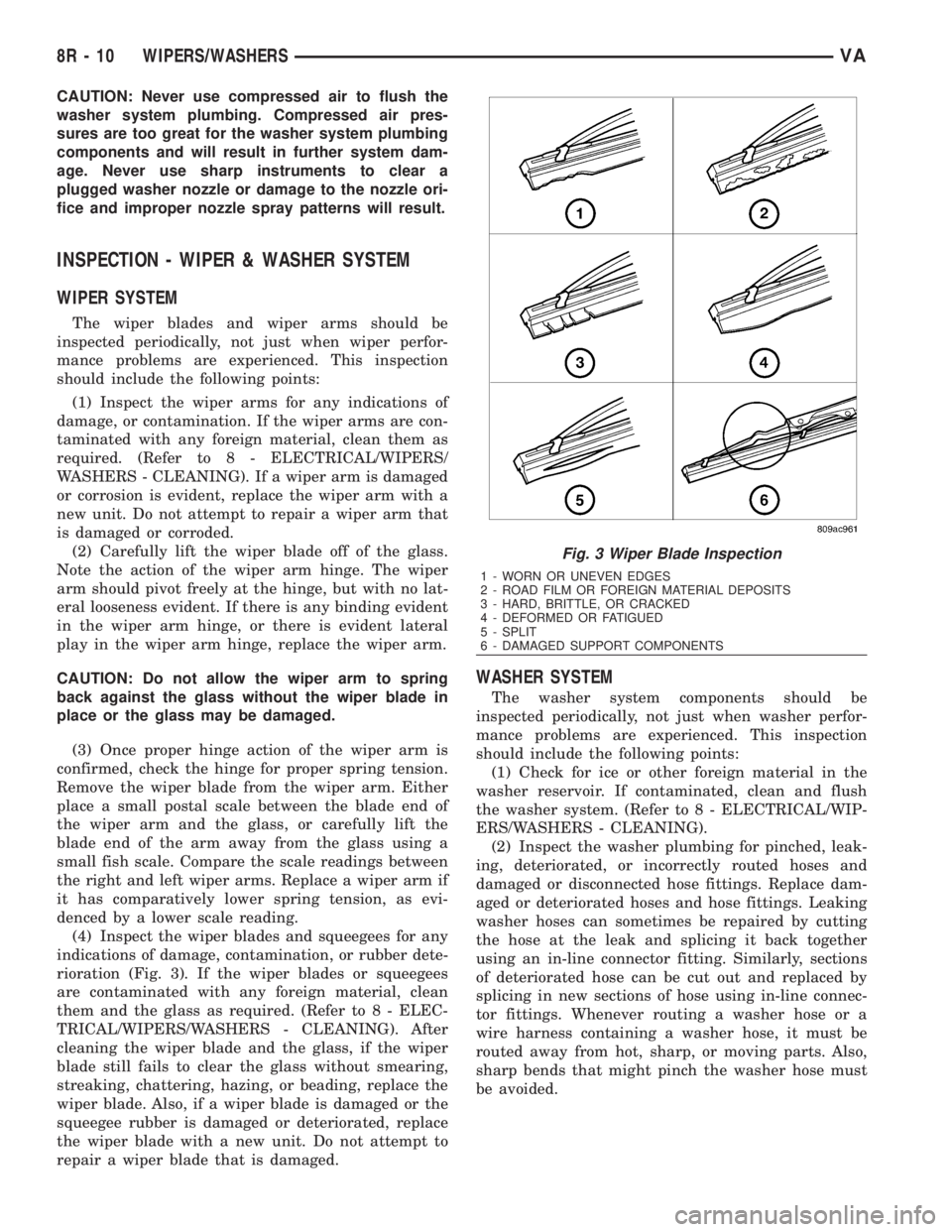
INSPECTION - WIPER & WASHER SYSTEM
WIPER SYSTEM
The wiper blades and wiper arms should be
inspected periodically, not just when wiper perfor-
mance problems are experienced. This inspection
should include the following points:
(1) Inspect the wiper arms for any indications of
damage, or contamination. If the wiper arms are con-
taminated with any foreign material, clean them as
required. (Refer to 8 - ELECTRICAL/WIPERS/
WASHERS - CLEANING). If a wiper arm is damaged
or corrosion is evident, replace the wiper arm with a
new unit. Do not attempt to repair a wiper arm that
is damaged or corroded.
(2) Carefully lift the wiper blade off of the glass.
Note the action of the wiper arm hinge. The wiper
arm should pivot freely at the hinge, but with no lat-
eral looseness evident. If there is any binding evident
in the wiper arm hinge, or there is evident lateral
play in the wiper arm hinge, replace the wiper arm.
CAUTION: Do not allow the wiper arm to spring
back against the glass without the wiper blade in
place or the glass may be damaged.
(3) Once proper hinge action of the wiper arm is
confirmed, check the hinge for proper spring tension.
Remove the wiper blade from the wiper arm. Either
place a small postal scale between the blade end of
the wiper arm and the glass, or carefully lift the
blade end of the arm away from the glass using a
small fish scale. Compare the scale readings between
the right and left wiper arms. Replace a wiper arm if
it has comparatively lower spring tension, as evi-
denced by a lower scale reading.
(4) Inspect the wiper blades and squeegees for any
indications of damage, contamination, or rubber dete-
rioration (Fig. 3). If the wiper blades or squeegees
are contaminated with any foreign material, clean
them and the glass as required. (Refer to 8 - ELEC-
TRICAL/WIPERS/WASHERS - CLEANING). After
cleaning the wiper blade and the glass, if the wiper
blade still fails to clear the glass without smearing,
streaking, chattering, hazing, or beading, replace the
wiper blade. Also, if a wiper blade is damaged or the
squeegee rubber is damaged or deteriorated, replace
the wiper blade with a new unit. Do not attempt to
repair a wiper blade that is damaged.
WASHER SYSTEM
The washer system components should be
inspected periodically, not just when washer perfor-
mance problems are experienced. This inspection
should include the following points:
(1) Check for ice or other foreign material in the
washer reservoir. If contaminated, clean and flush
the washer system. (Refer to 8 - ELECTRICAL/WIP-
ERS/WASHERS - CLEANING).
(2) Inspect the washer plumbing for pinched, leak-
ing, deteriorated, or incorrectly routed hoses and
damaged or disconnected hose fittings. Replace dam-
aged or deteriorated hoses and hose fittings. Leaking
washer hoses can sometimes be repaired by cutting
the hose at the leak and splicing it back together
using an in-line connector fitting. Similarly, sections
of deteriorated hose can be cut out and replaced by
splicing in new sections of hose using in-line connec-
tor fittings. Whenever routing a washer hose or a
wire harness containing a washer hose, it must be
routed away from hot, sharp, or moving parts. Also,
sharp bends that might pinch the washer hose must
be avoided.
Fig. 3 Wiper Blade Inspection
1 - WORN OR UNEVEN EDGES
2 - ROAD FILM OR FOREIGN MATERIAL DEPOSITS
3 - HARD, BRITTLE, OR CRACKED
4 - DEFORMED OR FATIGUED
5 - SPLIT
6 - DAMAGED SUPPORT COMPONENTS
8R - 10 WIPERS/WASHERSVA
Page 1054 of 2305

CHECK VALVE
DESCRIPTION
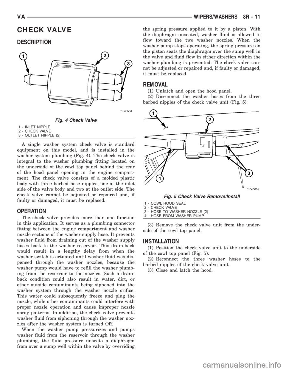
A single washer system check valve is standard
equipment on this model, and is installed in the
washer system plumbing (Fig. 4). The check valve is
integral to the washer plumbing fitting located on
the underside of the cowl top panel behind the rear
of the hood panel opening in the engine compart-
ment. The check valve consists of a molded plastic
body with three barbed hose nipples, one at the inlet
side of the valve body and two at the outlet side. The
check valve cannot be adjusted or repaired and, if
faulty or damaged, it must be replaced.
OPERATION
The check valve provides more than one function
in this application. It serves as a plumbing connector
fitting between the engine compartment and washer
nozzle sections of the washer supply hose. It prevents
washer fluid from draining out of the washer supply
hoses back to the washer reservoir. This drain-back
would result in a lengthy delay from when the
washer switch is actuated until washer fluid was dis-
pensed through the washer nozzles, because the
washer pump would have to refill the washer plumb-
ing from the reservoir to the nozzles. Such a drain-
back condition could also result in water, dirt, or
other outside contaminants being siphoned into the
washer system through the washer nozzle orifice.
This water could subsequently freeze and plug the
nozzle, while other contaminants could interfere with
proper nozzle operation and cause improper nozzle
spray patterns. In addition, the check valve prevents
washer fluid from siphoning through the washer noz-
zles after the washer system is turned Off.
When the washer pump pressurizes and pumps
washer fluid from the reservoir through the washer
plumbing, the fluid pressure unseats a diaphragm
from over a sump well within the valve by overridingthe spring pressure applied to it by a piston. With
the diaphragm unseated, washer fluid is allowed to
flow toward the two washer nozzles. When the
washer pump stops operating, the spring pressure on
the piston seats the diaphragm over the sump well in
the valve and fluid flow in either direction within the
washer plumbing is prevented. The check valve can-
not be adjusted or repaired and, if faulty or damaged,
it must be replaced.
REMOVAL
(1) Unlatch and open the hood panel.
(2) Disconnect the washer hoses from the three
barbed nipples of the check valve unit (Fig. 5).
(3) Remove the check valve unit from the under-
side of the cowl top panel.
INSTALLATION
(1) Position the check valve unit to the underside
of the cowl top panel (Fig. 5).
(2) Reconnect the three washer hoses to the
barbed nipples of the check valve unit.
(3) Close and latch the hood.
Fig. 4 Check Valve
1 - INLET NIPPLE
2 - CHECK VALVE
3 - OUTLET NIPPLE (2)
Fig. 5 Check Valve Remove/Install
1 - COWL HOOD SEAL
2 - CHECK VALVE
3 - HOSE TO WASHER NOZZLE (2)
4 - HOSE FROM WASHER PUMP
VAWIPERS/WASHERS 8R - 11
Page 1941 of 2305

will ensure correct wheel centering and maximum
wheel clamping.
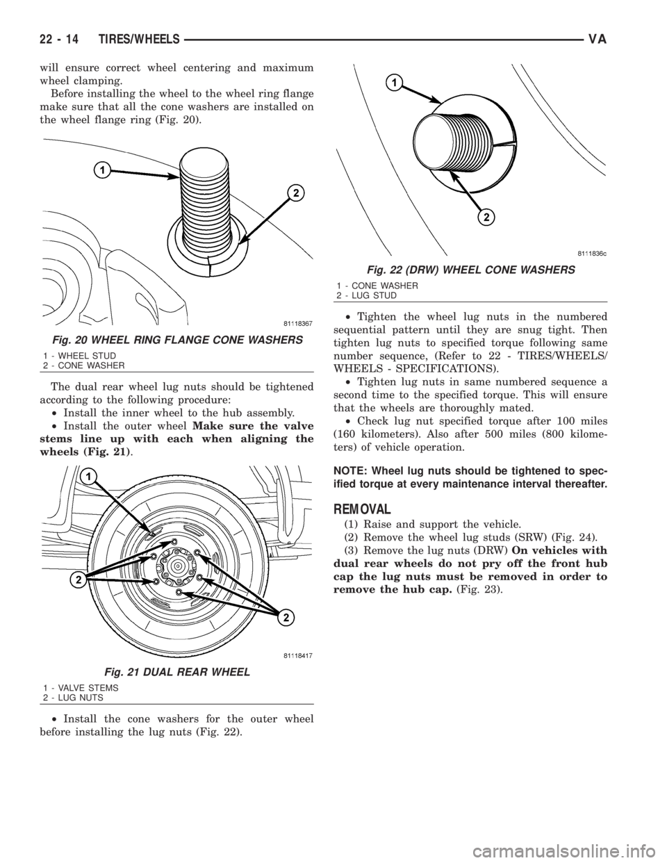
Before installing the wheel to the wheel ring flange
make sure that all the cone washers are installed on
the wheel flange ring (Fig. 20).
The dual rear wheel lug nuts should be tightened
according to the following procedure:
²Install the inner wheel to the hub assembly.
²Install the outer wheelMake sure the valve
stems line up with each when aligning the
wheels (Fig. 21).
²Install the cone washers for the outer wheel
before installing the lug nuts (Fig. 22).²Tighten the wheel lug nuts in the numbered
sequential pattern until they are snug tight. Then
tighten lug nuts to specified torque following same
number sequence, (Refer to 22 - TIRES/WHEELS/
WHEELS - SPECIFICATIONS).
²Tighten lug nuts in same numbered sequence a
second time to the specified torque. This will ensure
that the wheels are thoroughly mated.
²Check lug nut specified torque after 100 miles
(160 kilometers). Also after 500 miles (800 kilome-
ters) of vehicle operation.
NOTE: Wheel lug nuts should be tightened to spec-
ified torque at every maintenance interval thereafter.
REMOVAL
(1) Raise and support the vehicle.
(2) Remove the wheel lug studs (SRW) (Fig. 24).
(3) Remove the lug nuts (DRW)On vehicles with
dual rear wheels do not pry off the front hub
cap the lug nuts must be removed in order to
remove the hub cap.(Fig. 23).
Fig. 20 WHEEL RING FLANGE CONE WASHERS
1 - WHEEL STUD
2 - CONE WASHER
Fig. 21 DUAL REAR WHEEL
1 - VALVE STEMS
2 - LUG NUTS
Fig. 22 (DRW) WHEEL CONE WASHERS
1 - CONE WASHER
2 - LUG STUD
22 - 14 TIRES/WHEELSVA
Page 2070 of 2305

INSTALLATION
NOTE: Replacement of the PTFE thread sealing
tape is required anytime the rear A/C low pressure
switch is removed from the rear suction line line.
Failure to replace the sealing tape could result in a
rear refrigerant system leak.
(1) Remove the tape or plug from the rear suction
line fitting.
(2) Install PTFE thread sealing tape onto the rear
A/C low pressure switch and install the switch onto
the rear suction line. Tightened the A/C low pressure
switch to 10 N´m (88 in. lbs.).
(3) Connect the wiring harness connector to the
rear A/C low pressure switch.
(4) Install new insulating tape around the rear A/C
low pressure switch area.
(5) Reconnect the negative battery cable.
(6) Evacuate the rear refrigerant system (Refer to
24 - HEATING & AIR CONDITIONING/PLUMBING
- STANDARD PROCEDURE - REFRIGERANT SYS-
TEM EVACUATE).
(7) Charge the rear refrigerant system (Refer to 24
- HEATING & AIR CONDITIONING/PLUMBING -
STANDARD PROCEDURE - REFRIGERANT SYS-
TEM CHARGE).
(8) Install the cover onto the rear A/C evaporator
housing (Refer to 24 - HEATING & AIR CONDI-
TIONING/DISTRIBUTION - REAR/A/C EVAPORA-
TOR COVER-REAR - INSTALLATION).
BLOWER MOTOR RELAY
DESCRIPTION
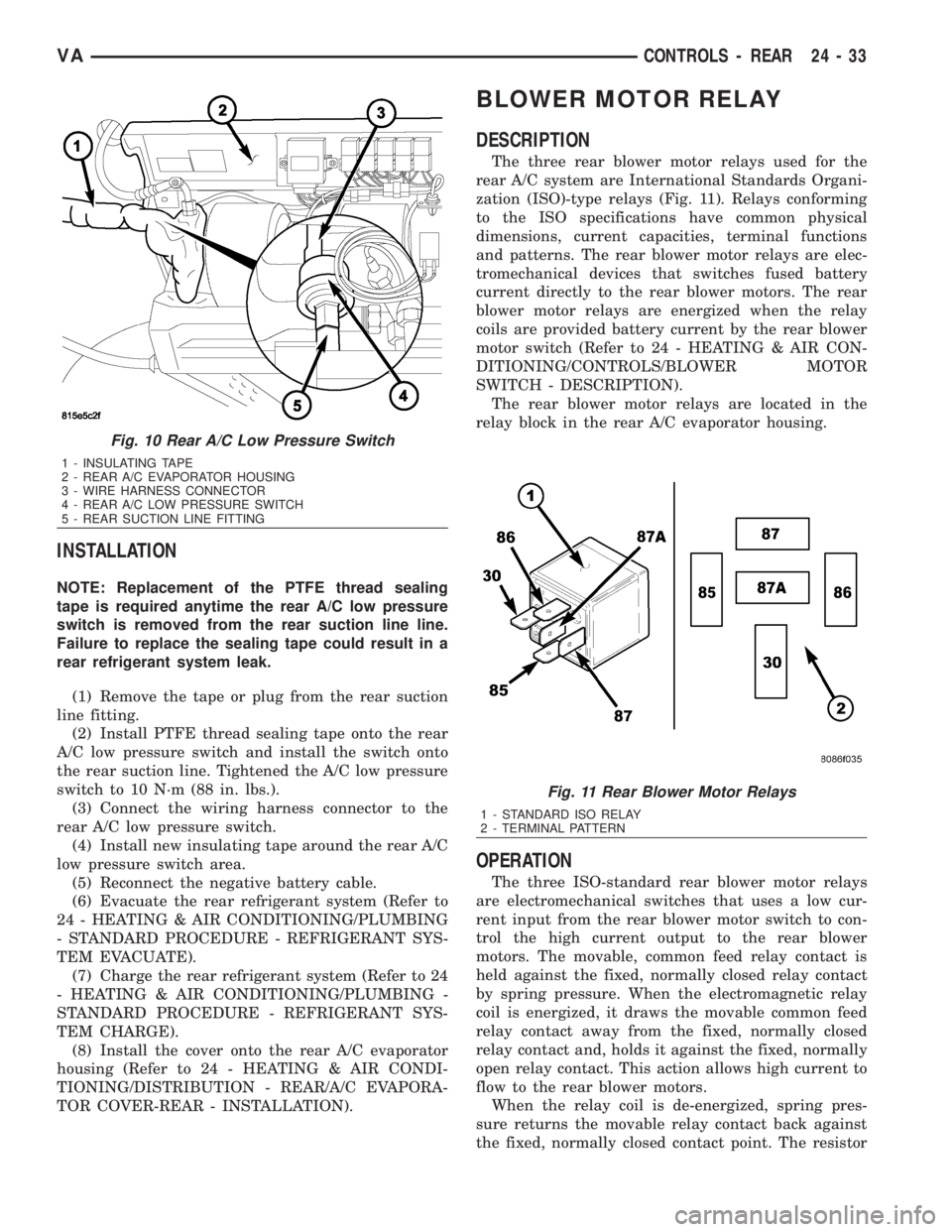
The three rear blower motor relays used for the
rear A/C system are International Standards Organi-
zation (ISO)-type relays (Fig. 11). Relays conforming
to the ISO specifications have common physical
dimensions, current capacities, terminal functions
and patterns. The rear blower motor relays are elec-
tromechanical devices that switches fused battery
current directly to the rear blower motors. The rear
blower motor relays are energized when the relay
coils are provided battery current by the rear blower
motor switch (Refer to 24 - HEATING & AIR CON-
DITIONING/CONTROLS/BLOWER MOTOR
SWITCH - DESCRIPTION).
The rear blower motor relays are located in the
relay block in the rear A/C evaporator housing.
OPERATION
The three ISO-standard rear blower motor relays
are electromechanical switches that uses a low cur-
rent input from the rear blower motor switch to con-
trol the high current output to the rear blower
motors. The movable, common feed relay contact is
held against the fixed, normally closed relay contact
by spring pressure. When the electromagnetic relay
coil is energized, it draws the movable common feed
relay contact away from the fixed, normally closed
relay contact and, holds it against the fixed, normally
open relay contact. This action allows high current to
flow to the rear blower motors.
When the relay coil is de-energized, spring pres-
sure returns the movable relay contact back against
the fixed, normally closed contact point. The resistor
Fig. 10 Rear A/C Low Pressure Switch
1 - INSULATING TAPE
2 - REAR A/C EVAPORATOR HOUSING
3 - WIRE HARNESS CONNECTOR
4 - REAR A/C LOW PRESSURE SWITCH
5 - REAR SUCTION LINE FITTING
Fig. 11 Rear Blower Motor Relays
1 - STANDARD ISO RELAY
2 - TERMINAL PATTERN
VACONTROLS - REAR 24 - 33