2006 MERCEDES-BENZ SPRINTER ABS
[x] Cancel search: ABSPage 9 of 2305

TABLE OF CONTENTS - Continued
A/C COMPRESSOR CONTROL SHORTED LOW (ACTIVE)....................132
AIR OUTLET TEMP SENSOR HIGH OR OPEN (ACTIVE).....................134
AIR OUTLET TEMP SENSOR SHORTED LOW (ACTIVE).....................136
ATC FUNCTION TEST COOL FAILURE....................................138
ATC FUNCTION TEST FAILURE..........................................138
ATC FUNCTION TEST HEAT FAILURE.....................................138
AUX FAN RELAY CONTROL HIGH OR OPEN (ACTIVE)......................140
AUX FAN RELAY CONTROL SHORTED LOW (ACTIVE)......................142
BLOWER STAGE 1 HIGH OR OPEN (ACTIVE)..............................144
BLOWER STAGE 1 SHORTED LOW (ACTIVE)..............................146
CABIN HEATER CONTROL HIGH OR OPEN (ACTIVE).......................148
CABIN HEATER CONTROL SHORTED LOW (ACTIVE).......................150
CIRC PUMP CONTROL HIGH OR OPEN (ACTIVE)..........................152
CIRC PUMP CONTROL SHORTED LOW (ACTIVE)..........................154
EVAP TEMP SENSOR HIGH OR OPEN (ACTIVE)...........................156
EVAP TEMP SENSOR SHORTED LOW (ACTIVE)...........................158
NO COMMUNICATION BUS (ACTIVE).....................................160
NO COMMUNICATION WITH ECM (ACTIVE)...............................163
NO COMMUNICATION WITH IC (ACTIVE)..................................165
RECIRC AIR SOLENOID CONTROL HIGH OR OPEN (ACTIVE)................167
RECIRC AIR SOLENOID CONTROL SHORTED LOW (ACTIVE)................169
REFRIG PRESS SENSOR HIGH OR OPEN (ACTIVE)........................171
REFRIG PRESS SENSOR SHORTED LOW (ACTIVE)........................173
WATER CYCLE VALVE CONTROL HIGH OR OPEN (ACTIVE).................175
WATER CYCLE VALVE CONTROL SHORTED LOW (ACTIVE).................177
INSTRUMENT CLUSTER
AMBIENT TEMP SENSOR OPEN/SHORT TO BATTERY......................179
AMBIENT TEMP SENSOR SHORT TO GROUND............................181
FUEL LEVEL SENSOR OPEN/SHORT TO BATTERY.........................182
FUEL LEVEL SENSOR SHORT TO GROUND...............................184
INSTRUMENT CLUSTER INTERNAL FAILURE B1043........................185
INSTRUMENT CLUSTER INTERNAL FAILURE B1053........................186
INSTRUMENT CLUSTER OVERVOLTAGE..................................187
NO CAN COMMUNICATION WITH ABS....................................188
NO CAN COMMUNICATION WITH ECM...................................190
NO CAN COMMUNICATION WITH TCM....................................192
PREGLOW INDICATOR LAMP FAILURE...................................194
SRS INDICATOR LAMP FAILURE.........................................195
POWER DOOR LOCKS/RKE
DRIVER DOOR AJAR INDICATOR DRIVER CIRCUIT SHORT TO GROUND......196
PASSENGER DOOR AJAR INDICATOR DRIVER CIRCUIT SHORT TO GROUND .198
REPLACE CONTROL MODULE..........................................200
RKE INTERFACE CIRCUIT SHORT TO GROUND - CTM......................201
RKE INTERFACE CIRCUIT SHORT TO GROUND - SKREEM..................203
RKE INTERFACE CIRCUIT SHORT TO VOLTAGE - CTM.....................205
RKE INTERFACE CIRCUIT SHORT TO VOLTAGE - SKREEM..................206
THE ACM HAS UNLOCKED THE DOORS..................................208
UNKNOWN TROUBLE CODE UNKNOWN DTC TYPE 2......................209
*RKE INOPERATIVE....................................................210
*RKE POOR RANGE...................................................211
iv
Page 26 of 2305

WARNING:REASSEMBLE ALL COMPONENTS
BEFORE ROAD TESTING A VEHICLE. DO NOT
TRY TO READ THE DRBIIITSCREEN OR
OTHER TEST EQUIPMENT DURING A TEST
DRIVE. DO NOT HANG THE DRBIIITOR OTHER
TEST EQUIPMENT FROM THE REARVIEW
MIRROR DURING A TEST DRIVE. HAVE AN
ASSISTANT AVAILABLE TO OPERATE THE
DRBIIITOR OTHER TEST EQUIPMENT.
FAILURE TO FOLLOW THESE INSTRUCTIONS
CAN RESULT IN PERSONAL INJURY OR
DEATH.
5.0 REQUIRED TOOLS AND
EQUIPMENT
DRBIIIt(diagnostic read-out box)
Jumper wires
Ohmmeter
Voltmeter
Test Light
8310 Airbag System Load Tool
8443 SRS Airbag System Load Tool
9001 R F Detector
6.0 GLOSSARY OF TERMS
ABSantilock brake system
ACMairbag control module
ACTactuator
AECMairbag electronic control module
(ACM)
ASDMairbag system diagnostic module
(ACM)
AT Cautomatic temperature control
CABcontroller antilock bake
CANcontroller area network
CHMcabin heater module
CPAconnector positive assurance
CTMcentral timer module
DABdriver airbag
DCHAdiesel cabin heater assist (cabin
heater)
DLCdata link connector
DTCdiagnostic trouble code
DRdriver
EBLelectric back lite (rear window de
fogger)
ECMengine control module
GCCGulf Coast Countries
HBMheater booster module
HVACheater ventilation, air conditioning
ICinstrument cluster
MICmechanical instrument cluster
RSMRain Sensor Module
SAshifter assembly
SKREEMsentry key remote entry module
SSMsecurity system module
TCMtransmission control module
13
GENERAL INFORMATION
Page 123 of 2305
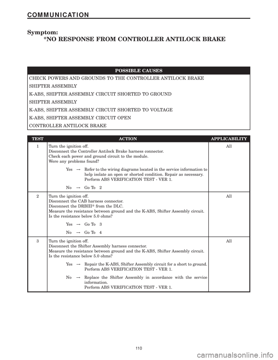
Symptom:
*NO RESPONSE FROM CONTROLLER ANTILOCK BRAKE
POSSIBLE CAUSES
CHECK POWERS AND GROUNDS TO THE CONTROLLER ANTILOCK BRAKE
SHIFTER ASSEMBLY
K-ABS, SHIFTER ASSEMBLY CIRCUIT SHORTED TO GROUND
SHIFTER ASSEMBLY
K-ABS, SHIFTER ASSEMBLY CIRCUIT SHORTED TO VOLTAGE
K-ABS, SHIFTER ASSEMBLY CIRCUIT OPEN
CONTROLLER ANTILOCK BRAKE
TEST ACTION APPLICABILITY
1 Turn the ignition off.
Disconnect the Controller Antilock Brake harness connector.
Check each power and ground circuit to the module.
Were any problems found?All
Ye s!Refer to the wiring diagrams located in the service information to
help isolate an open or shorted condition. Repair as necessary.
Perform ABS VERIFICATION TEST - VER 1.
No!Go To 2
2 Turn the ignition off.
Disconnect the CAB harness connector.
Disconnect the DRBIIItfrom the DLC.
Measure the resistance between ground and the K-ABS, Shifter Assembly circuit.
Is the resistance below 5.0 ohms?All
Ye s!Go To 3
No!Go To 4
3 Turn the ignition off.
Disconnect the Shifter Assembly harness connector.
Measure the resistance between ground and the K-ABS, Shifter Assembly circuit.
Is the resistance below 5.0 ohms?All
Ye s!Repair the K-ABS, Shifter Assembly circuit for a short to ground.
Perform ABS VERIFICATION TEST - VER 1.
No!Replace the Shifter Assembly in accordance with the service
information.
Perform ABS VERIFICATION TEST - VER 1.
11 0
COMMUNICATION
Page 124 of 2305
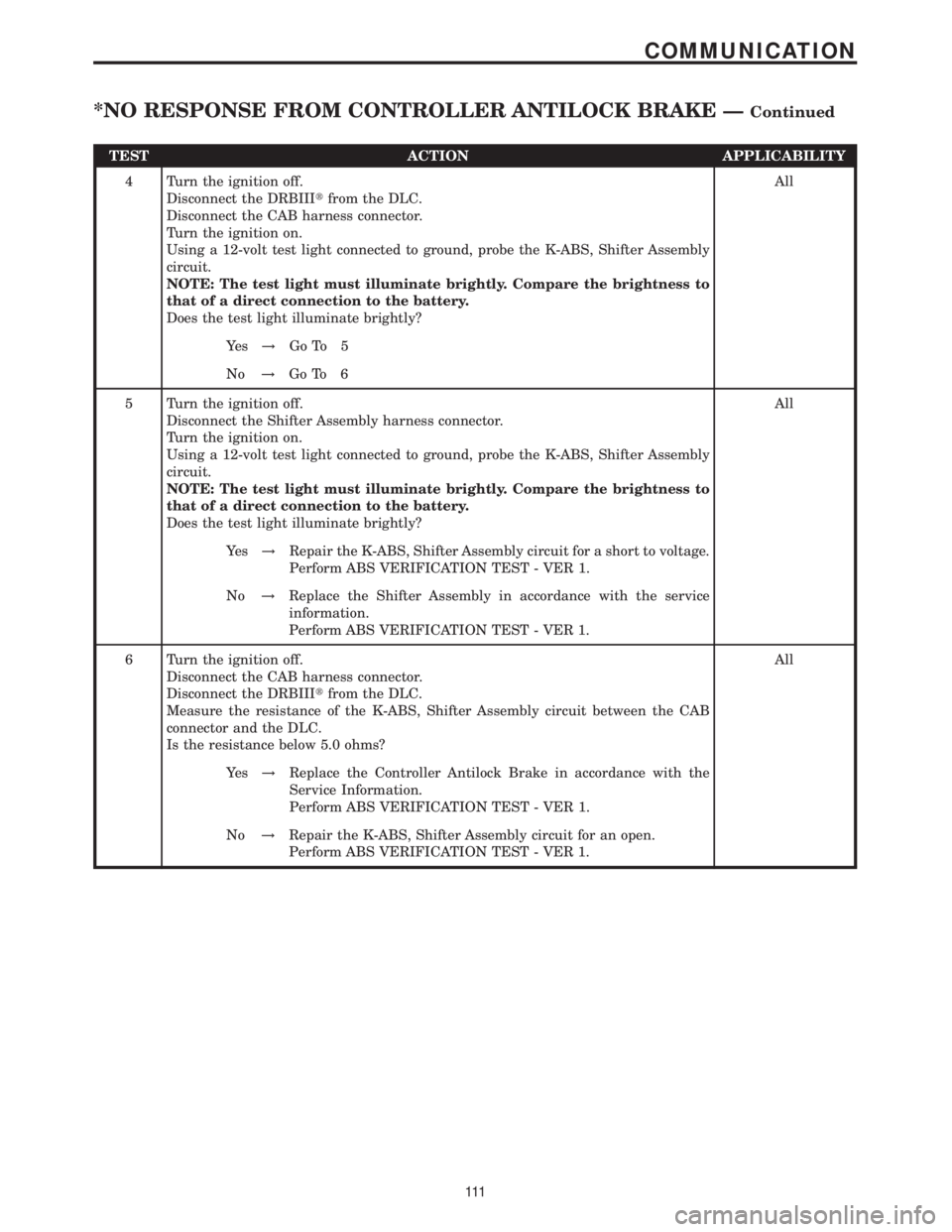
TEST ACTION APPLICABILITY
4 Turn the ignition off.
Disconnect the DRBIIItfrom the DLC.
Disconnect the CAB harness connector.
Turn the ignition on.
Using a 12-volt test light connected to ground, probe the K-ABS, Shifter Assembly
circuit.
NOTE: The test light must illuminate brightly. Compare the brightness to
that of a direct connection to the battery.
Does the test light illuminate brightly?All
Ye s!Go To 5
No!Go To 6
5 Turn the ignition off.
Disconnect the Shifter Assembly harness connector.
Turn the ignition on.
Using a 12-volt test light connected to ground, probe the K-ABS, Shifter Assembly
circuit.
NOTE: The test light must illuminate brightly. Compare the brightness to
that of a direct connection to the battery.
Does the test light illuminate brightly?All
Ye s!Repair the K-ABS, Shifter Assembly circuit for a short to voltage.
Perform ABS VERIFICATION TEST - VER 1.
No!Replace the Shifter Assembly in accordance with the service
information.
Perform ABS VERIFICATION TEST - VER 1.
6 Turn the ignition off.
Disconnect the CAB harness connector.
Disconnect the DRBIIItfrom the DLC.
Measure the resistance of the K-ABS, Shifter Assembly circuit between the CAB
connector and the DLC.
Is the resistance below 5.0 ohms?All
Ye s!Replace the Controller Antilock Brake in accordance with the
Service Information.
Perform ABS VERIFICATION TEST - VER 1.
No!Repair the K-ABS, Shifter Assembly circuit for an open.
Perform ABS VERIFICATION TEST - VER 1.
111
COMMUNICATION
*NO RESPONSE FROM CONTROLLER ANTILOCK BRAKE ÐContinued
Page 137 of 2305
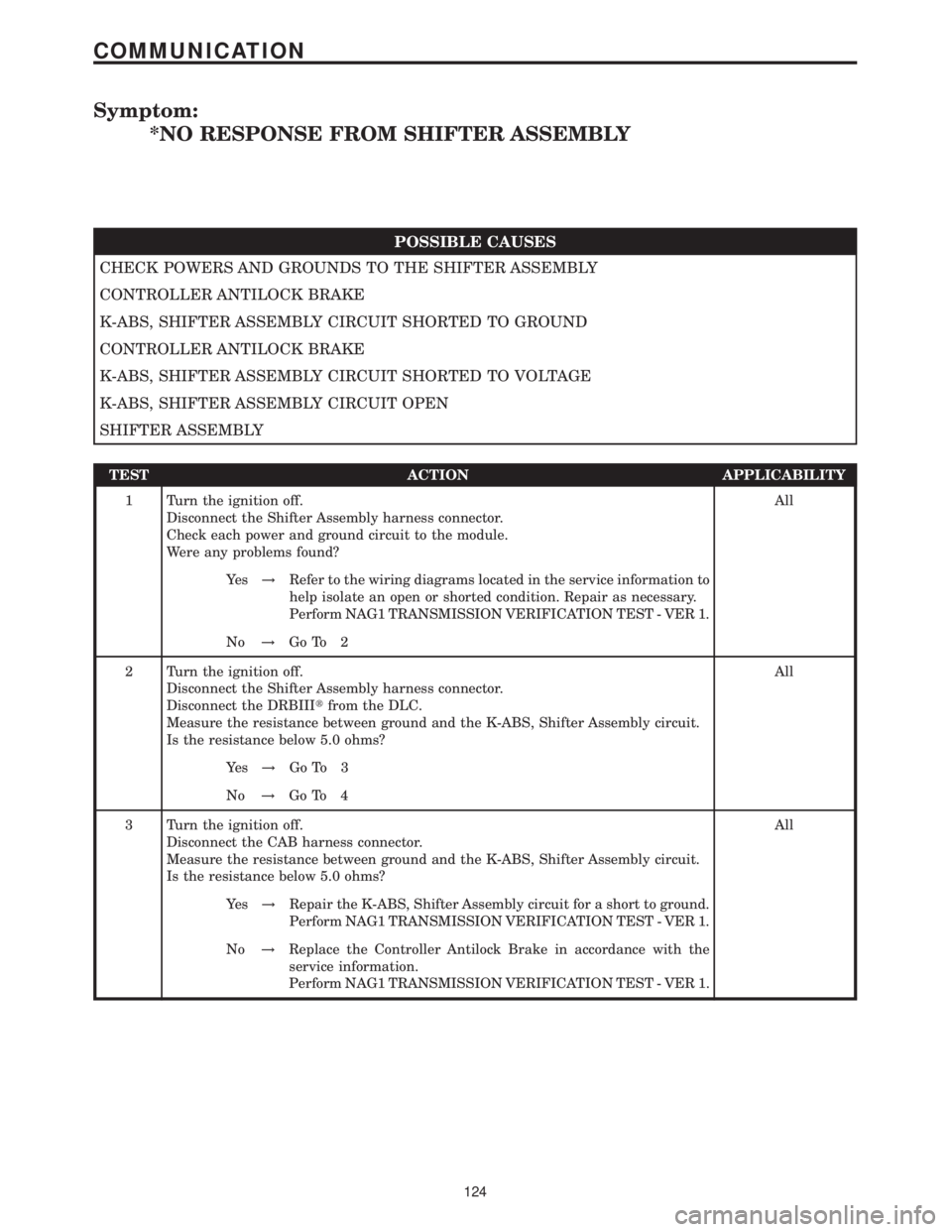
Symptom:
*NO RESPONSE FROM SHIFTER ASSEMBLY
POSSIBLE CAUSES
CHECK POWERS AND GROUNDS TO THE SHIFTER ASSEMBLY
CONTROLLER ANTILOCK BRAKE
K-ABS, SHIFTER ASSEMBLY CIRCUIT SHORTED TO GROUND
CONTROLLER ANTILOCK BRAKE
K-ABS, SHIFTER ASSEMBLY CIRCUIT SHORTED TO VOLTAGE
K-ABS, SHIFTER ASSEMBLY CIRCUIT OPEN
SHIFTER ASSEMBLY
TEST ACTION APPLICABILITY
1 Turn the ignition off.
Disconnect the Shifter Assembly harness connector.
Check each power and ground circuit to the module.
Were any problems found?All
Ye s!Refer to the wiring diagrams located in the service information to
help isolate an open or shorted condition. Repair as necessary.
Perform NAG1 TRANSMISSION VERIFICATION TEST - VER 1.
No!Go To 2
2 Turn the ignition off.
Disconnect the Shifter Assembly harness connector.
Disconnect the DRBIIItfrom the DLC.
Measure the resistance between ground and the K-ABS, Shifter Assembly circuit.
Is the resistance below 5.0 ohms?All
Ye s!Go To 3
No!Go To 4
3 Turn the ignition off.
Disconnect the CAB harness connector.
Measure the resistance between ground and the K-ABS, Shifter Assembly circuit.
Is the resistance below 5.0 ohms?All
Ye s!Repair the K-ABS, Shifter Assembly circuit for a short to ground.
Perform NAG1 TRANSMISSION VERIFICATION TEST - VER 1.
No!Replace the Controller Antilock Brake in accordance with the
service information.
Perform NAG1 TRANSMISSION VERIFICATION TEST - VER 1.
124
COMMUNICATION
Page 138 of 2305
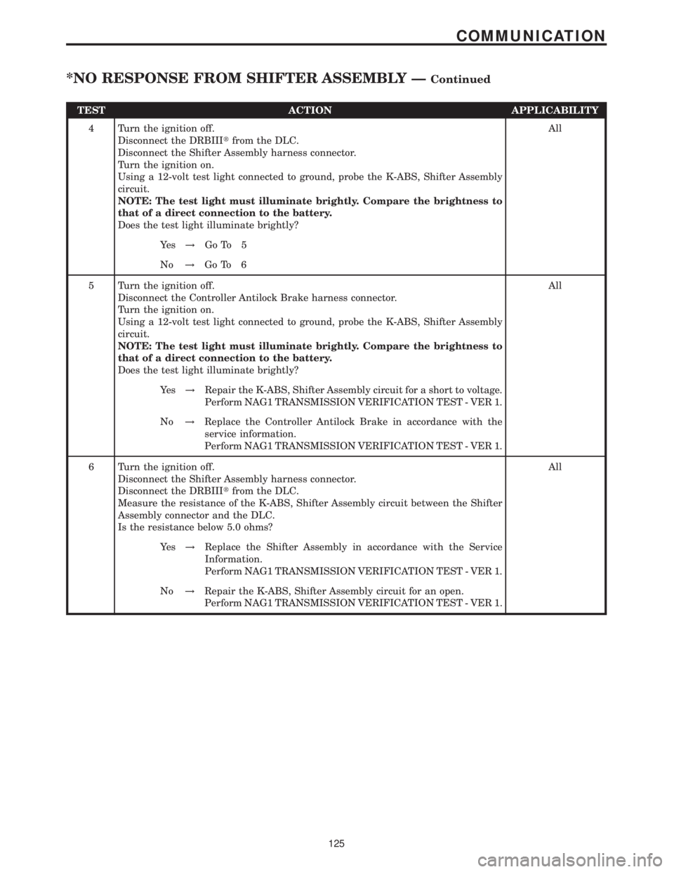
TEST ACTION APPLICABILITY
4 Turn the ignition off.
Disconnect the DRBIIItfrom the DLC.
Disconnect the Shifter Assembly harness connector.
Turn the ignition on.
Using a 12-volt test light connected to ground, probe the K-ABS, Shifter Assembly
circuit.
NOTE: The test light must illuminate brightly. Compare the brightness to
that of a direct connection to the battery.
Does the test light illuminate brightly?All
Ye s!Go To 5
No!Go To 6
5 Turn the ignition off.
Disconnect the Controller Antilock Brake harness connector.
Turn the ignition on.
Using a 12-volt test light connected to ground, probe the K-ABS, Shifter Assembly
circuit.
NOTE: The test light must illuminate brightly. Compare the brightness to
that of a direct connection to the battery.
Does the test light illuminate brightly?All
Ye s!Repair the K-ABS, Shifter Assembly circuit for a short to voltage.
Perform NAG1 TRANSMISSION VERIFICATION TEST - VER 1.
No!Replace the Controller Antilock Brake in accordance with the
service information.
Perform NAG1 TRANSMISSION VERIFICATION TEST - VER 1.
6 Turn the ignition off.
Disconnect the Shifter Assembly harness connector.
Disconnect the DRBIIItfrom the DLC.
Measure the resistance of the K-ABS, Shifter Assembly circuit between the Shifter
Assembly connector and the DLC.
Is the resistance below 5.0 ohms?All
Ye s!Replace the Shifter Assembly in accordance with the Service
Information.
Perform NAG1 TRANSMISSION VERIFICATION TEST - VER 1.
No!Repair the K-ABS, Shifter Assembly circuit for an open.
Perform NAG1 TRANSMISSION VERIFICATION TEST - VER 1.
125
COMMUNICATION
*NO RESPONSE FROM SHIFTER ASSEMBLY ÐContinued
Page 176 of 2305
Symptom:
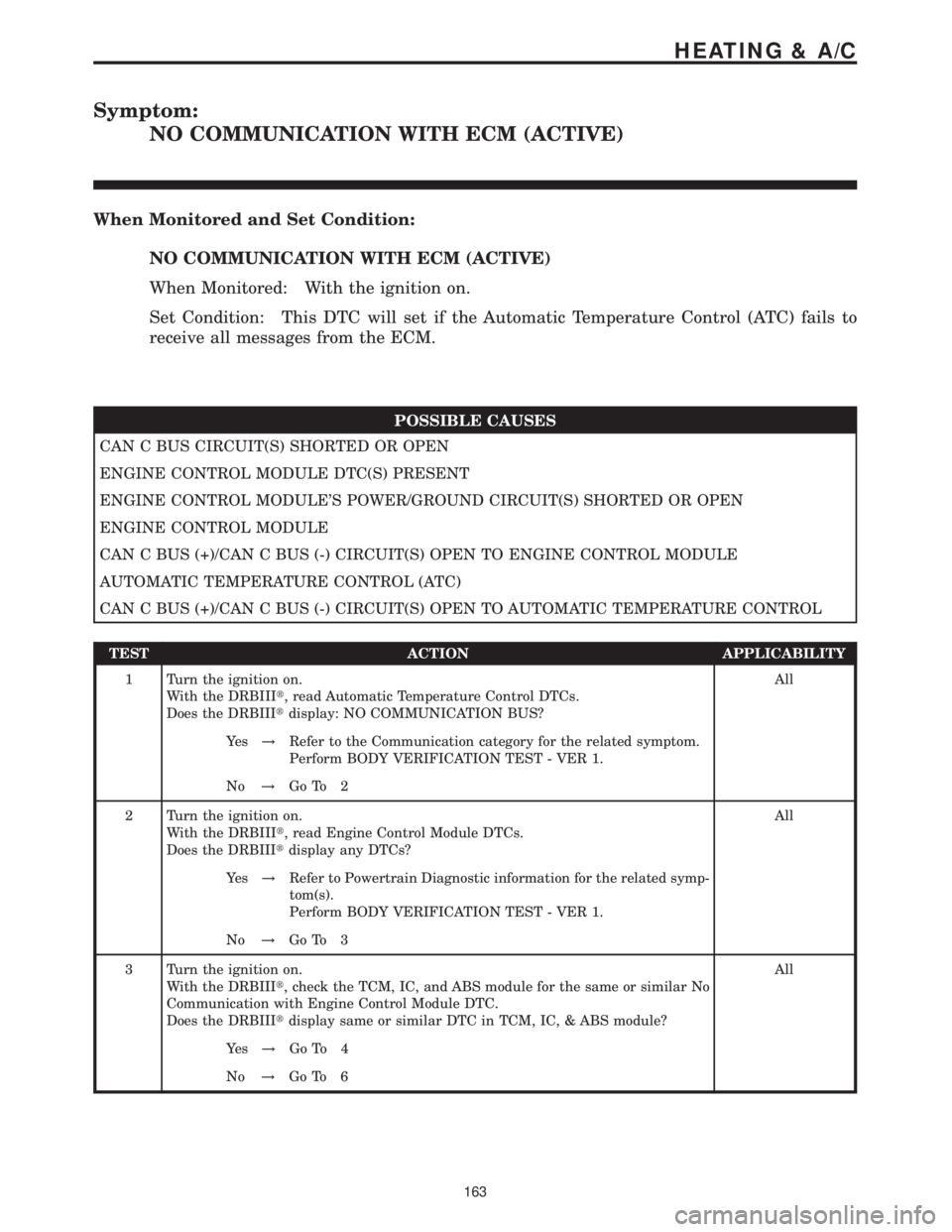
NO COMMUNICATION WITH ECM (ACTIVE)
When Monitored and Set Condition:
NO COMMUNICATION WITH ECM (ACTIVE)
When Monitored: With the ignition on.
Set Condition: This DTC will set if the Automatic Temperature Control (ATC) fails to
receive all messages from the ECM.
POSSIBLE CAUSES
CAN C BUS CIRCUIT(S) SHORTED OR OPEN
ENGINE CONTROL MODULE DTC(S) PRESENT
ENGINE CONTROL MODULE'S POWER/GROUND CIRCUIT(S) SHORTED OR OPEN
ENGINE CONTROL MODULE
CAN C BUS (+)/CAN C BUS (-) CIRCUIT(S) OPEN TO ENGINE CONTROL MODULE
AUTOMATIC TEMPERATURE CONTROL (ATC)
CAN C BUS (+)/CAN C BUS (-) CIRCUIT(S) OPEN TO AUTOMATIC TEMPERATURE CONTROL
TEST ACTION APPLICABILITY
1 Turn the ignition on.
With the DRBIIIt, read Automatic Temperature Control DTCs.
Does the DRBIIItdisplay: NO COMMUNICATION BUS?All
Ye s!Refer to the Communication category for the related symptom.
Perform BODY VERIFICATION TEST - VER 1.
No!Go To 2
2 Turn the ignition on.
With the DRBIIIt, read Engine Control Module DTCs.
Does the DRBIIItdisplay any DTCs?All
Ye s!Refer to Powertrain Diagnostic information for the related symp-
tom(s).
Perform BODY VERIFICATION TEST - VER 1.
No!Go To 3
3 Turn the ignition on.
With the DRBIIIt, check the TCM, IC, and ABS module for the same or similar No
Communication with Engine Control Module DTC.
Does the DRBIIItdisplay same or similar DTC in TCM, IC, & ABS module?All
Ye s!Go To 4
No!Go To 6
163
HEATING & A/C
Page 178 of 2305
Symptom:
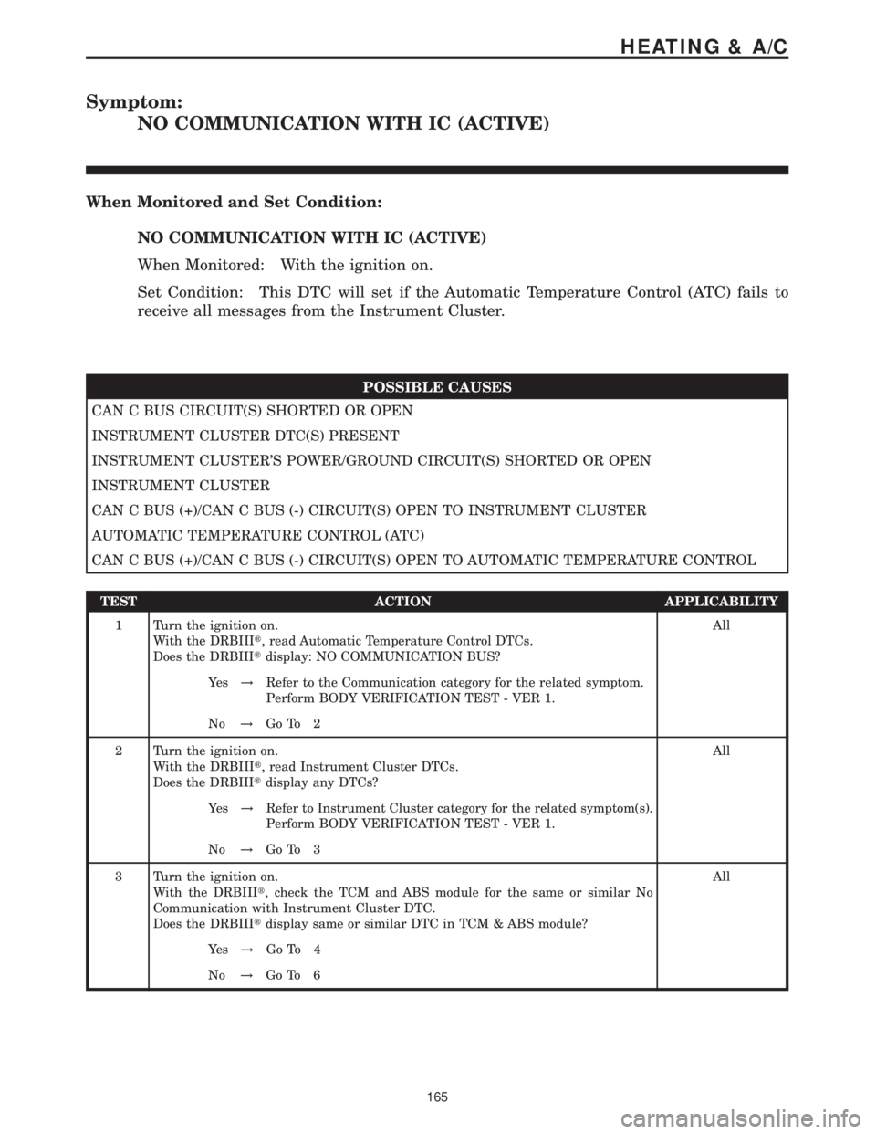
NO COMMUNICATION WITH IC (ACTIVE)
When Monitored and Set Condition:
NO COMMUNICATION WITH IC (ACTIVE)
When Monitored: With the ignition on.
Set Condition: This DTC will set if the Automatic Temperature Control (ATC) fails to
receive all messages from the Instrument Cluster.
POSSIBLE CAUSES
CAN C BUS CIRCUIT(S) SHORTED OR OPEN
INSTRUMENT CLUSTER DTC(S) PRESENT
INSTRUMENT CLUSTER'S POWER/GROUND CIRCUIT(S) SHORTED OR OPEN
INSTRUMENT CLUSTER
CAN C BUS (+)/CAN C BUS (-) CIRCUIT(S) OPEN TO INSTRUMENT CLUSTER
AUTOMATIC TEMPERATURE CONTROL (ATC)
CAN C BUS (+)/CAN C BUS (-) CIRCUIT(S) OPEN TO AUTOMATIC TEMPERATURE CONTROL
TEST ACTION APPLICABILITY
1 Turn the ignition on.
With the DRBIIIt, read Automatic Temperature Control DTCs.
Does the DRBIIItdisplay: NO COMMUNICATION BUS?All
Ye s!Refer to the Communication category for the related symptom.
Perform BODY VERIFICATION TEST - VER 1.
No!Go To 2
2 Turn the ignition on.
With the DRBIIIt, read Instrument Cluster DTCs.
Does the DRBIIItdisplay any DTCs?All
Ye s!Refer to Instrument Cluster category for the related symptom(s).
Perform BODY VERIFICATION TEST - VER 1.
No!Go To 3
3 Turn the ignition on.
With the DRBIIIt, check the TCM and ABS module for the same or similar No
Communication with Instrument Cluster DTC.
Does the DRBIIItdisplay same or similar DTC in TCM & ABS module?All
Ye s!Go To 4
No!Go To 6
165
HEATING & A/C