2006 MERCEDES-BENZ SPRINTER center console
[x] Cancel search: center consolePage 1511 of 2305

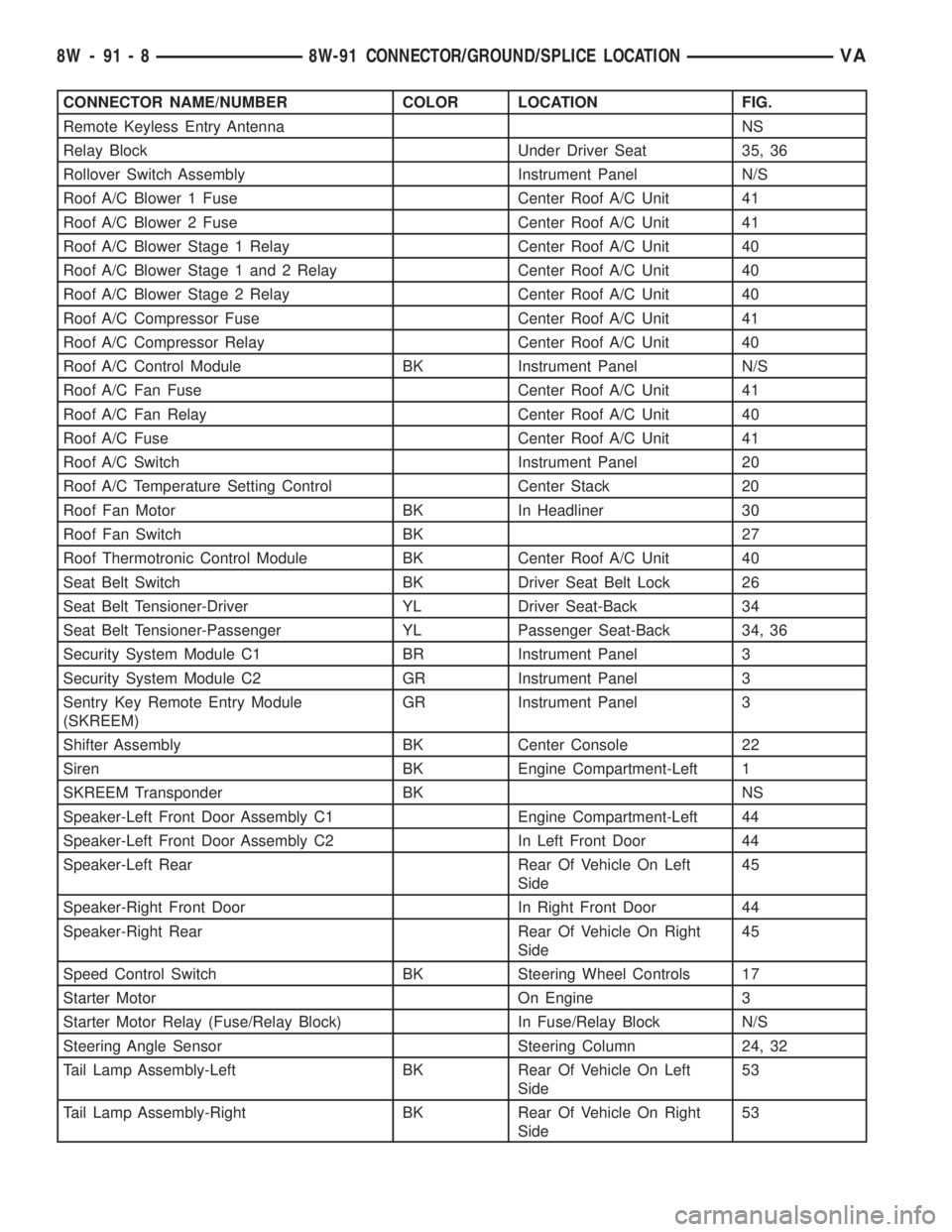
CONNECTOR NAME/NUMBER COLOR LOCATION FIG.
Remote Keyless Entry Antenna NS
Relay Block Under Driver Seat 35, 36
Rollover Switch Assembly Instrument Panel N/S
Roof A/C Blower 1 Fuse Center Roof A/C Unit 41
Roof A/C Blower 2 Fuse Center Roof A/C Unit 41
Roof A/C Blower Stage 1 Relay Center Roof A/C Unit 40
Roof A/C Blower Stage 1 and 2 Relay Center Roof A/C Unit 40
Roof A/C Blower Stage 2 Relay Center Roof A/C Unit 40
Roof A/C Compressor Fuse Center Roof A/C Unit 41
Roof A/C Compressor Relay Center Roof A/C Unit 40
Roof A/C Control Module BK Instrument Panel N/S
Roof A/C Fan Fuse Center Roof A/C Unit 41
Roof A/C Fan Relay Center Roof A/C Unit 40
Roof A/C Fuse Center Roof A/C Unit 41
Roof A/C Switch Instrument Panel 20
Roof A/C Temperature Setting Control Center Stack 20
Roof Fan Motor BK In Headliner 30
Roof Fan Switch BK 27
Roof Thermotronic Control Module BK Center Roof A/C Unit 40
Seat Belt Switch BK Driver Seat Belt Lock 26
Seat Belt Tensioner-Driver YL Driver Seat-Back 34
Seat Belt Tensioner-Passenger YL Passenger Seat-Back 34, 36
Security System Module C1 BR Instrument Panel 3
Security System Module C2 GR Instrument Panel 3
Sentry Key Remote Entry Module
(SKREEM)GR Instrument Panel 3
Shifter Assembly BK Center Console 22
Siren BK Engine Compartment-Left 1
SKREEM Transponder BK NS
Speaker-Left Front Door Assembly C1 Engine Compartment-Left 44
Speaker-Left Front Door Assembly C2 In Left Front Door 44
Speaker-Left Rear Rear Of Vehicle On Left
Side45
Speaker-Right Front Door In Right Front Door 44
Speaker-Right Rear Rear Of Vehicle On Right
Side45
Speed Control Switch BK Steering Wheel Controls 17
Starter Motor On Engine 3
Starter Motor Relay (Fuse/Relay Block) In Fuse/Relay Block N/S
Steering Angle Sensor Steering Column 24, 32
Tail Lamp Assembly-Left BK Rear Of Vehicle On Left
Side53
Tail Lamp Assembly-Right BK Rear Of Vehicle On Right
Side53
8W - 91 - 8 8W-91 CONNECTOR/GROUND/SPLICE LOCATIONVA
Page 1783 of 2305

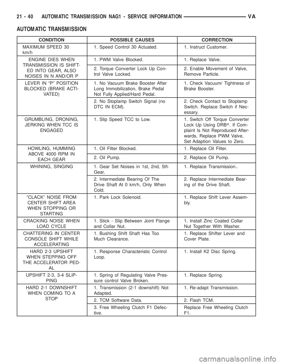
AUTOMATIC TRANSMISSION
CONDITION POSSIBLE CAUSES CORRECTION
MAXIMUM SPEED 30
km/h1. Speed Control 30 Actuated. 1. Instruct Customer.
ENGINE DIES WHEN
TRANSMISSION IS SHIFT-
ED INTO GEAR, ALSO
NOISES IN N AND/OR P1. PWM Valve Blocked. 1. Replace Valve.
2. Torque Converter Lock Up Con-
trol Valve Locked.2. Enable Movement of Valve,
Remove Particle.
LEVER IN ªPº POSITION
BLOCKED (BRAKE ACTI-
VATED)1. No Vacuum Brake Booster After
Long Immobilization, Brake Pedal
Not Fully Applied/Hard Pedal.1. Check Vacuum/ Tightness of
Brake Booster.
2. No Stoplamp Switch Signal (no
DTC IN ECM).2. Check Contact to Stoplamp
Switch. Replace Switch if Nec-
essary.
GRUMBLING, DRONING,
JERKING WHEN TCC IS
ENGAGED1. Slip Speed TCC to Low. 1. Switch Off Torque Converter
Lock Up Using DRBT. If Com-
plaint Is Not Reproduced After-
wards, Replace PWM Valve,
Set Adaption Values to Zero.
HOWLING, HUMMING
ABOVE 4000 RPM IN
EACH GEAR1. Oil Filter Blocked. 1. Replace Oil Filter.
2. Oil Pump. 2. Replace Oil Pump.
WHINING, SINGING 1. Gear Set Noises in 1st, 2nd, 5th
Gear.1. Replace Transmission..
2. Intermediate Bearing Of The
Drive Shaft At 0 km/h, Only When
Cold.2. Replace Intermediate Bear-
ing of the Drive Shaft.
9CLACKº NOISE FROM
CENTER SHIFT AREA
WHEN STOPPING OR
STARTING1. Park Lock Solenoid. 1. Replace Shift Lever Assem-
bly.
CRACKING NOISE WHEN
LOAD CYCLE1. Stick - Slip Between Joint Flange
and Collar Nut.1. Install Zinc Coated Collar
Nut Together With Washer.
CHATTERING IN CENTER
CONSOLE SHIFT WHILE
ACCELERATING1. Bushing Shift Shaft Has Too
Much Clearance.1. Replace Shifter Lever and
Cover Plate.
HARD 2-3 UPSHIFT
WHEN STEPPING OFF
THE ACCELERATOR PED-
AL1. Response Characteristic Control
Loop.1. Install K2 Disc Spring.
UPSHIFT 2-3, 3-4 SLIP-
PING1. Spring of Regulating Valve Pres-
sure control Valve Broken.1. Replace Spring.
HARD 2-1 DOWNSHIFT
WHEN COMING TO A
STOP1. Transmission (2-1 downshift) Not
Adapted.1. Re-adapt Transmission.
2. TCM Software Data. 2. Flash TCM.
3. Free Wheeling Clutch F1 Defec-
tive.Replace Free Wheeling Clutch
F1.
21 - 40 AUTOMATIC TRANSMISSION NAG1 - SERVICE INFORMATIONVA
Page 1911 of 2305

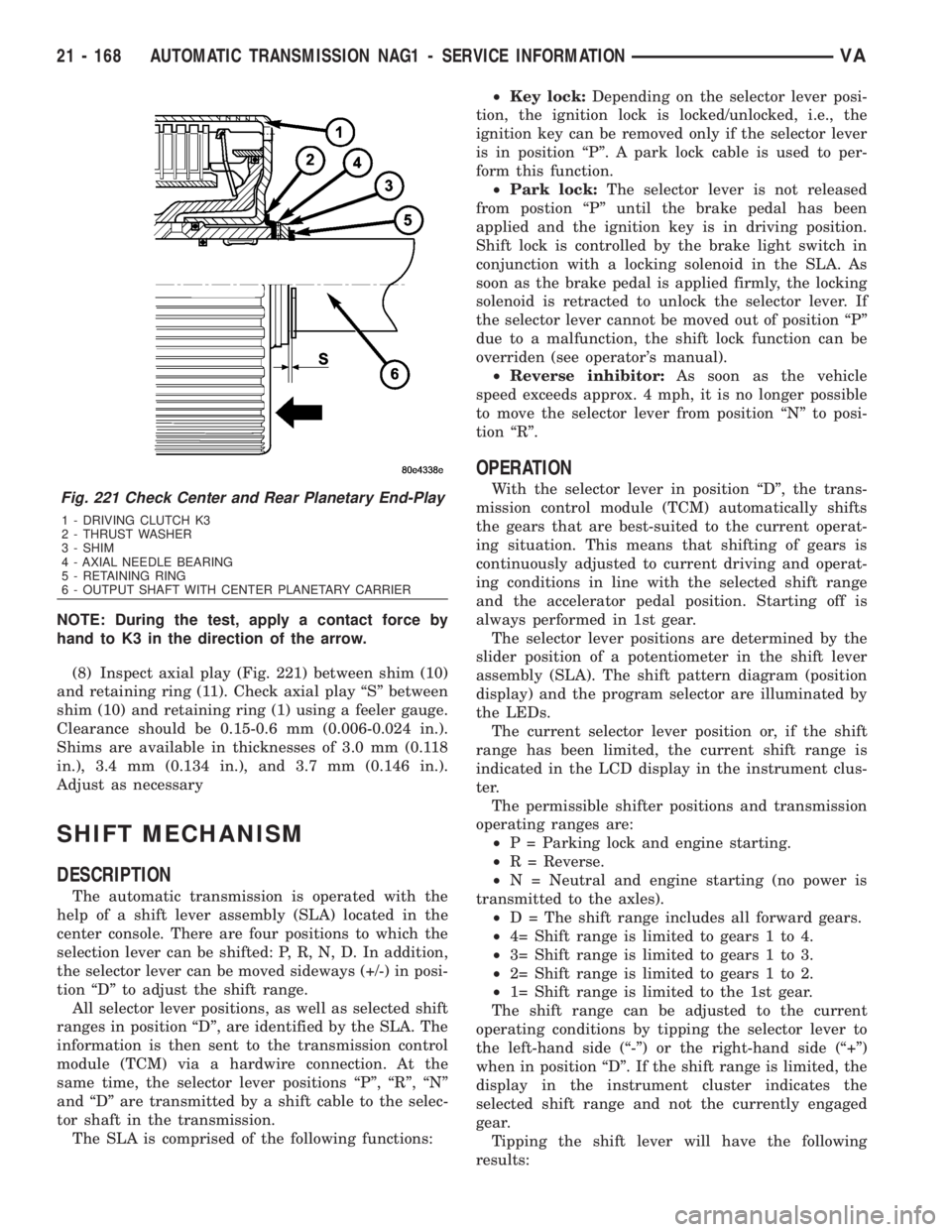
NOTE: During the test, apply a contact force by
hand to K3 in the direction of the arrow.
(8) Inspect axial play (Fig. 221) between shim (10)
and retaining ring (11). Check axial play ªSº between
shim (10) and retaining ring (1) using a feeler gauge.
Clearance should be 0.15-0.6 mm (0.006-0.024 in.).
Shims are available in thicknesses of 3.0 mm (0.118
in.), 3.4 mm (0.134 in.), and 3.7 mm (0.146 in.).
Adjust as necessary
SHIFT MECHANISM
DESCRIPTION
The automatic transmission is operated with the
help of a shift lever assembly (SLA) located in the
center console. There are four positions to which the
selection lever can be shifted: P, R, N, D. In addition,
the selector lever can be moved sideways (+/-) in posi-
tion ªDº to adjust the shift range.
All selector lever positions, as well as selected shift
ranges in position ªDº, are identified by the SLA. The
information is then sent to the transmission control
module (TCM) via a hardwire connection. At the
same time, the selector lever positions ªPº, ªRº, ªNº
and ªDº are transmitted by a shift cable to the selec-
tor shaft in the transmission.
The SLA is comprised of the following functions:²Key lock:Depending on the selector lever posi-
tion, the ignition lock is locked/unlocked, i.e., the
ignition key can be removed only if the selector lever
is in position ªPº. A park lock cable is used to per-
form this function.
²Park lock:The selector lever is not released
from postion ªPº until the brake pedal has been
applied and the ignition key is in driving position.
Shift lock is controlled by the brake light switch in
conjunction with a locking solenoid in the SLA. As
soon as the brake pedal is applied firmly, the locking
solenoid is retracted to unlock the selector lever. If
the selector lever cannot be moved out of position ªPº
due to a malfunction, the shift lock function can be
overriden (see operator's manual).
²Reverse inhibitor:As soon as the vehicle
speed exceeds approx. 4 mph, it is no longer possible
to move the selector lever from position ªNº to posi-
tion ªRº.
OPERATION
With the selector lever in position ªDº, the trans-
mission control module (TCM) automatically shifts
the gears that are best-suited to the current operat-
ing situation. This means that shifting of gears is
continuously adjusted to current driving and operat-
ing conditions in line with the selected shift range
and the accelerator pedal position. Starting off is
always performed in 1st gear.
The selector lever positions are determined by the
slider position of a potentiometer in the shift lever
assembly (SLA). The shift pattern diagram (position
display) and the program selector are illuminated by
the LEDs.
The current selector lever position or, if the shift
range has been limited, the current shift range is
indicated in the LCD display in the instrument clus-
ter.
The permissible shifter positions and transmission
operating ranges are:
²P = Parking lock and engine starting.
²R = Reverse.
²N = Neutral and engine starting (no power is
transmitted to the axles).
²D = The shift range includes all forward gears.
²4= Shift range is limited to gears 1 to 4.
²3= Shift range is limited to gears 1 to 3.
²2= Shift range is limited to gears 1 to 2.
²1= Shift range is limited to the 1st gear.
The shift range can be adjusted to the current
operating conditions by tipping the selector lever to
the left-hand side (ª-º) or the right-hand side (ª+º)
when in position ªDº. If the shift range is limited, the
display in the instrument cluster indicates the
selected shift range and not the currently engaged
gear.
Tipping the shift lever will have the following
results:Fig. 221 Check Center and Rear Planetary End-Play
1 - DRIVING CLUTCH K3
2 - THRUST WASHER
3 - SHIM
4 - AXIAL NEEDLE BEARING
5 - RETAINING RING
6 - OUTPUT SHAFT WITH CENTER PLANETARY CARRIER
21 - 168 AUTOMATIC TRANSMISSION NAG1 - SERVICE INFORMATIONVA