2006 MERCEDES-BENZ SPRINTER window
[x] Cancel search: windowPage 12 of 2305

TABLE OF CONTENTS - Continued
FUSES (FUSE BLOCK NO. 2)............................................274
FUSES (FUSE BLOCK NO. 3)............................................276
FUSES (FUSE/RELAY BLOCK)...........................................278
HOOD AJAR SWITCH - BLACK...........................................278
HORN (VTSS).........................................................278
IGNITION LOCK SWITCH - BLACK........................................278
INSTRUMENT CLUSTER C1.............................................279
INSTRUMENT CLUSTER C2 - WHITE.....................................279
INTRUSION SENSOR NO. 1 - BLACK.....................................279
INTRUSION SENSOR NO. 2 - BLACK.....................................279
INTRUSION SENSOR NO. 3 - BLACK.....................................280
MASTER DOOR LOCK SWITCH..........................................280
PANIC ALARM SWITCH - BLACK.........................................280
FUSES (PDC).........................................................281
RADIO C1 - BLACK....................................................282
RADIO C2............................................................282
RECIRCULATED AIR SOLENOID VALVE...................................282
REFRIGERANT PRESSURE SENSOR.....................................282
A/C AUXILIARY FAN RELAY (RELAY BLOCK)...............................284
CIRCULATION PUMP RELAY-CABIN HEATER MODULE (RELAY BLOCK).......284
D+ RELAY NO. 2 (RELAY BLOCK)........................................284
FAN STAGE 1 RELAY (RELAY BLOCK)....................................284
OPTIONAL EQUIPMENT RELAY (RELAY BLOCK)...........................284
REMOTE KEYLESS ENTRY ANTENNA....................................284
SEAT BELT SWITCH...................................................284
SEAT BELT TENSIONER-DRIVER - YELLOW...............................285
SEAT BELT TENSIONER-PASSENGER - YELLOW...........................285
SECURITY SYSTEM MODULE C1 - BROWN...............................285
SECURITY SYSTEM MODULE C2 - LT. GREEN.............................286
SENTRY KEY REMOTE ENTRY MODULE (SKREEM)........................286
SHIFTER ASSEMBLY - BLACK...........................................286
SIREN - BLACK.......................................................286
STEERING ANGLE SENSOR............................................287
TOWING/INTRUSION SENSOR ON/OFF SWITCH...........................287
TRANSMISSION CONTROL MODULE C1 - BLACK..........................287
TRANSMISSION CONTROL MODULE C2 - BLACK..........................288
WATER CYCLE VALVE..................................................288
WINDOW DEFOGGER-LEFT REAR.......................................288
WINDOW DEFOGGER-RIGHT REAR......................................288
10.0 SCHEMATIC DIAGRAMS................................................289
10.1AIRBAG SYSTEM.................................................289
10.2COMMUNICATION................................................290
10.2.1COMMUNICATION K-LINES................................290
10.2.2CAN BUS NETWORK......................................291
10.3HEATING & A/C...................................................292
10.3.1AUTOMATIC TEMPERATURE CONTROL (ATC)................292
10.3.2CABIN HEATER MODULE (CHM)............................293
10.3.3HEATER BOOSTER MODULE (HBM).........................294
10.4INSTRUMENT CLUSTER...........................................295
vii
Page 23 of 2305

the A-pillar. The SKREEM receives radio messages
from the RKE transmitter (fob) and sends com-
mands via the RKE Interface circuit to the CTM. If
the vehicle is equipped with VTSS, the Security
System Module will be connected in series between
the SKREEM and the CTM.
Confirmation of the RKE Lock/Unlock state is
accomplished via the turn signals. When the vehicle
is locked via RKE the turn signals will flash three
times. When it is unlocked via RKE, the turn
signals will flash one time. If the vehicle has been
unlocked via RKE and no door is opened within 40
seconds, the entire vehicle will be locked again
automatically.
If a transmitter (fob) is operated more than 255
times in succession beyond the range of the receiver
(SKREEM), the RKE portion of the key will become
inoperative. In order to put it back in synchroniza-
tion it will be necessary to have ALL the other
transmitters that are used with this vehicle avail-
able and follow the following procedure:
1. Cycle the ignition on and off 2 times within 6
seconds (leave in off position).
2. Press the lock or unlock button of the disabled
transmitter within 3 seconds of turning the
ignition off.
3. Press any button (lock or unlock) 3 more times
within 6 seconds.
4. Wait 10 seconds.
5. Press any button of ALL other transmitters
belonging to this vehicle at least once within
the next 20 seconds.
For problems related to the Immobilizer function
of the SKREEM, see Service Information.
3.5.3 AUTO DOOR LOCKS
Whenever the engine is started, the CTM receives
a message to lock all doors except the drivers door.
This is accomplished through the D+ Relay. The D+
Relay is controlled by the Instrument Cluster which
receives a command from the ECM that the engine
is running. This relay supplies power to the CTM
(for auto locking), the daytime running lamps and
the rear window defogger.
3.5.4 ACCIDENT RESPONSE
The CTM is hardwired to the Airbag Control
Module through the Enhanced Accident Report
Driver circuit. Anytime the vehicle airbags are
deployed, the CTM will unlock all doors and a
9Crash9DTC will be stored in memory. The door
locks will be inoperative until that code is cleared. If
the vehicle is severly jarred, but not enough to
deploy the airbags, it is possible that the DTC could
be set and therefore the door locks would be inop-
erable. Whenever the door locks are not opera-tional, use the DRBIII and check DTC's . If the code
9ACM has unlocked the doors9appears, use the
DRBIII and erase it.
3.6 VEHICLE THEFT SECURITY SYSTEM
(VTSS)
The Security System Module (SSM) is located
under the driver's seat. The SSM communicates
with the DRBIII over the K-line. If equipped the
Vehicle Theft Security System will monitor the
following:
²door jamb switches
²hood ajar switch
²ignition switch
²interior of the vehicle for movement
²longitudinal and transverse movement of the
vehicle
²rear defogger grids for glass breakage
²trailer connector
To arm the system the hood and all of the doors
must be closed when the vehicle is locked with the
RKE transmitter or with the use of the key in the
driver door. If the key is used, it must be held in the
lock position for 2 seconds. When the system is first
activated, the hazard lamps will flash 3 times. Also
with the system armed, the Towing/Intrusion Sen-
sor On/Off Switch indicator will flash to indicate an
armed system. To disarm the system use the RKE
or the driver door lock cylinder. Unlocking and
opening one of the other doors with the system
armed will trip the vehicle theft security system.
Interior monitoring is done by the use of an
Intrusion Sensor located in the front headliner and
with one or two sensors in the ceiling of the cargo
area depending on how the vehicle is equipped.
Monitoring of the interior of the vehicle will begin
after the system has been armed for 30 seconds. The
on/off switch located on the instrument panel can be
used to turn off this feature with the ignition switch
in either the Locked/Off or ACC position. The vehi-
cle tow-monitoring feature can also be switched off
using this switch. Re-locking the vehicle a second
time will reactivate these features.
If a trailer is connected to the vehicle when the
system is armed, the SSM will sense a resistance
change on the turn signal circuits if the trailer
harness becomes disconnected and will trip the
alarm.
Tripping the vehicle theft security system will
cause the hazard lamps to flash and the siren to
sound at 30-second intervals. The siren is equipped
with it's own self-contained battery. In the event the
vehicle's battery power is disconnected the siren
will continue to sound on it's own.
10
GENERAL INFORMATION
Page 26 of 2305

WARNING:REASSEMBLE ALL COMPONENTS
BEFORE ROAD TESTING A VEHICLE. DO NOT
TRY TO READ THE DRBIIITSCREEN OR
OTHER TEST EQUIPMENT DURING A TEST
DRIVE. DO NOT HANG THE DRBIIITOR OTHER
TEST EQUIPMENT FROM THE REARVIEW
MIRROR DURING A TEST DRIVE. HAVE AN
ASSISTANT AVAILABLE TO OPERATE THE
DRBIIITOR OTHER TEST EQUIPMENT.
FAILURE TO FOLLOW THESE INSTRUCTIONS
CAN RESULT IN PERSONAL INJURY OR
DEATH.
5.0 REQUIRED TOOLS AND
EQUIPMENT
DRBIIIt(diagnostic read-out box)
Jumper wires
Ohmmeter
Voltmeter
Test Light
8310 Airbag System Load Tool
8443 SRS Airbag System Load Tool
9001 R F Detector
6.0 GLOSSARY OF TERMS
ABSantilock brake system
ACMairbag control module
ACTactuator
AECMairbag electronic control module
(ACM)
ASDMairbag system diagnostic module
(ACM)
AT Cautomatic temperature control
CABcontroller antilock bake
CANcontroller area network
CHMcabin heater module
CPAconnector positive assurance
CTMcentral timer module
DABdriver airbag
DCHAdiesel cabin heater assist (cabin
heater)
DLCdata link connector
DTCdiagnostic trouble code
DRdriver
EBLelectric back lite (rear window de
fogger)
ECMengine control module
GCCGulf Coast Countries
HBMheater booster module
HVACheater ventilation, air conditioning
ICinstrument cluster
MICmechanical instrument cluster
RSMRain Sensor Module
SAshifter assembly
SKREEMsentry key remote entry module
SSMsecurity system module
TCMtransmission control module
13
GENERAL INFORMATION
Page 299 of 2305

SECURITY SYSTEM MODULE C2 - LT. GREENCAV CIRCUIT FUNCTION
1 16DG/YL INTRUSION SENSOR INTERFACE
2 16GY/BL WINDOW DEFOGGER-LEFT REAR OUTPUT
3 16GY WINDOW DEFOGGER RELAY-RIGHT REAR OUTPUT
4 20DG/BK INTRUSION SENSOR 1 SIGNAL
5- -
6- -
7 20GY/BK INTRUSION SENSOR 2 SIGNAL
8 16GY/DG K-CTM/SSM
9 18BK/BL SIREN SIGNAL CONTROL
10 20DG/WT/BL INTRUSION SENSOR 3 SIGNAL
11 16WT/BL RKE INTERFACE
12 16WT/BL/RD SECURITY SYSTEM INTERFACE
SENTRY KEY REMOTE ENTRY MODULE (SKREEM)CAV CIRCUIT FUNCTION
1 18YL RKE ANTENNA
2 16BR GROUND
3 16RD/YL FUSED B(+)
4 16BK/WT LEFT TURN SIGNAL
5 20DG/WT CAN C BUS (+)
6 20DG CAN C BUS (-)
7 16BK/YL FUSED IGNITION SWITCH OUTPUT (RUN-START)
8 20WT/DG K-SKREEM
9 16WT/BL/RD (EXCEPT
VTSS)RKE INTERFACE
9 16WT/BL/RD (VTSS) SECURITY SYSTEM INTERFACE
10 18DG/YL TURN SIGNAL/ANTI-THEFT ALARM RELAY-LEFT/RIGHT CONTROL
11 20BR TRANSPONDER COIL (+)
12 - TRANSPONDER COIL (-)
SHIFTER ASSEMBLY - BLACKCAV CIRCUIT FUNCTION
1- -
2 20GY/DG/RD LAMP DRIVER
3 20BL/DG K-ABS/SHIFTER ASSEMBLY
4 18BR GROUND
5 20BK/BL/RD BRAKE LAMP SWITCH
6 20DG/WT CAN C BUS (+)
7 20DG CAN C BUS (-)
8 18BK/DG TRANSMISSION RELAY OUTPUT
9 16WT/BL/RD FUSED IGNITION SWITCH OUTPUT (RUN-START)
10 16WT/RD BACK-UP LAMP
SIREN - BLACKCAV CIRCUIT FUNCTION
1 18RD/DG FUSED B(+)
2 18BR GROUND
3 18BK/BL SIREN SIGNAL CONTROL
C
O
N
N
E
C
T
O
R
P
I
N
O
U
T
S
286
CONNECTOR PINOUTS
Page 301 of 2305

TRANSMISSION CONTROL MODULE C2 - BLACKCAV CIRCUIT FUNCTION
12 20BL/GY N2 INPUT SPEED SENSOR
13 20BK/BL SENSOR SUPPLY VOLTAGE
14 16WT 1-2/4-5 SOLENOID CONTROL
15 16YL 3-4 SOLENOID CONTROL
16 16WT/BL 2-3 SOLENOID CONTROL
17 16YL/BL TCC SOLENOID CONTROL
33 20PK SENSOR GROUND
34 20GY/BL TEMPERATURE SENSOR-P/N SWITCH
35 20BL/DG N3 INPUT SPEED SENSOR
36 16BR/GY MODULATION PRESSURE SOLENOID CONTROL
37 16BK/RD SHIFT PRESSURE SOLENOID CONTROL
38 16BK SOLENOID SUPPLY VOLTAGE
H 20DG/WT CAN C BUS (+)
L 20DG CAN C BUS (-)
WATER CYCLE VALVECAV CIRCUIT FUNCTION
1 18BR/VT WATER CYCLE VALVE CONTROL
2 18BR GROUND
WINDOW DEFOGGER-LEFT REARCAV CIRCUIT FUNCTION
1 16GY (DEFOGGER RE-
LAYS)WINDOW DEFOGGER RELAY-LEFT REAR OUTPUT
1 16GY (EXCEPT DEFOGGER
RELAYS)WINDOW DEFOGGER-LEFT REAR OUTPUT
2 16BR GROUND
WINDOW DEFOGGER-RIGHT REARCAV CIRCUIT FUNCTION
1 16GY (DEFOGGER RE-
LAYS)WINDOW DEFOGGER RELAY-RIGHT REAR OUTPUT
1 16GY (EXCEPT DEFOGGER
RELAYS)WINDOW DEFOGGER-RIGHT REAR SIGNAL
2 16BR GROUND
C
O
N
N
E
C
T
O
R
P
I
N
O
U
T
S
288
CONNECTOR PINOUTS
Page 708 of 2305

FASTENER IDENTIFICATION
DESCRIPTION
The SAE bolt strength grades range from grade 2
to grade 8. The higher the grade number, the greater
the bolt strength. Identification is determined by the
line marks on the top of each bolt head. The actual
bolt strength grade corresponds to the number of line
marks plus 2. The most commonly used metric bolt
strength classes are 9.8 and 10.9. The metric
strength class identification number is imprinted on
the head of the bolt. The higher the class number,
the greater the bolt strength. Some metric nuts are
imprinted with a single-digit strength class on the
nut face. Refer to the Fastener Identification and
Fastener Strength Charts (Fig. 2) and (Fig. 3).
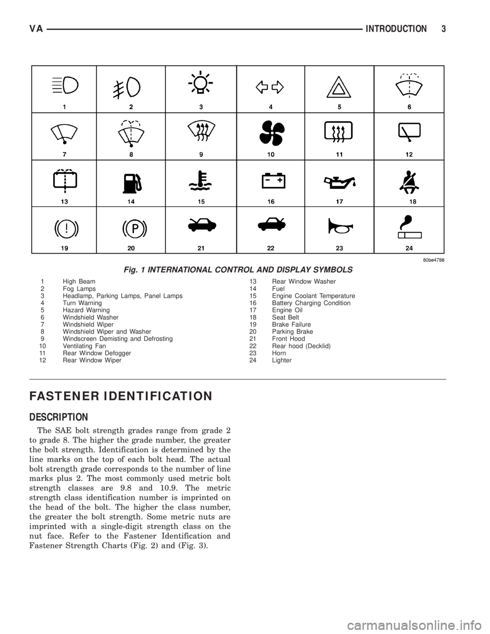
Fig. 1 INTERNATIONAL CONTROL AND DISPLAY SYMBOLS
1 High Beam 13 Rear Window Washer
2 Fog Lamps 14 Fuel
3 Headlamp, Parking Lamps, Panel Lamps 15 Engine Coolant Temperature
4 Turn Warning 16 Battery Charging Condition
5 Hazard Warning 17 Engine Oil
6 Windshield Washer 18 Seat Belt
7 Windshield Wiper 19 Brake Failure
8 Windshield Wiper and Washer 20 Parking Brake
9 Windscreen Demisting and Defrosting 21 Front Hood
10 Ventilating Fan 22 Rear hood (Decklid)
11 Rear Window Defogger 23 Horn
12 Rear Window Wiper 24 Lighter
VAINTRODUCTION 3
Page 902 of 2305

HEATED SYSTEMS
TABLE OF CONTENTS
page page
HEATED GLASS........................... 1
HEATED MIRRORS......................... 9HEATED SEATS........................... 10
HEATED GLASS
TABLE OF CONTENTS
page page
HEATED GLASS
DESCRIPTION..........................1
OPERATION............................1
DIAGNOSIS AND TESTING
ELECTRIC BACKLIGHT (EBL) SYSTEM.....2
REAR WINDOW DEFOGGER RELAY
DESCRIPTION..........................3
OPERATION............................3
REMOVAL.............................4
INSTALLATION..........................4REAR WINDOW DEFOGGER SWITCH
DESCRIPTION..........................4
OPERATION............................4
DIAGNOSIS AND TESTING
REAR WINDOW DEFOGGER SWITCH......5
REMOVAL.............................6
INSTALLATION..........................6
REAR WINDOW DEFOGGER GRID
STANDARD PROCEDURE
GRID LINE AND TERMINAL REPAIR........7
HEATED GLASS
DESCRIPTION
CAUTION: Grid lines can be damaged or scraped
off with sharp instruments. Care should be taken in
cleaning glass or removing foreign materials,
decals or stickers. Normal glass cleaning solvents
or hot water used with rags or toweling is recom-
mended.
The rear window defogger system, also known as
the electric backlight (EBL), consists of a backglass
with two vertical bus bars linked by a series of grid
lines fired onto the inside surface of the rear window.
The EBL system is turned On or Off by a control
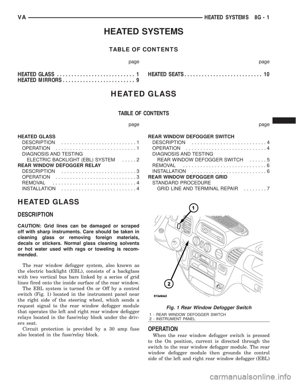
switch (Fig. 1) located in the instrument panel near
the right side of the steering wheel, which sends a
request signal to the rear window defogger module
that operates the left and right rear window defogger
relays located in the fuse/relay block under the driv-
ers seat.
Circuit protection is provided by a 30 amp fuse
also located in the fuse/relay block.
OPERATION
When the rear window defogger switch is pressed
to the On position, current is directed through the
switch to the rear window defogger module. The rear
window defogger module then grounds the control
side of the left and right rear window defogger (EBL)
Fig. 1 Rear Window Defogger Switch
1 - REAR WINDOW DEFOGGER SWITCH
2 - INSTRUMENT PANEL
VAHEATED SYSTEMS 8G - 1
Page 903 of 2305

relays which allows battery current to flow to the
rear window defogger grid lines. The heated grid
lines heat the rear glass to help clear the rear win-
dow surfaces of fog or frost.
The electric backlight (EBL) system is controlled
by the EBL timing circuity, which is integral to the
rear window defogger module. A yellow indicator in
the switch will illuminate to indicate when the EBL
system is turned on.
NOTE: The EBL system turns off automatically after
approximately 10 minutes of initial operation. Each
following activation cycle of the EBL system will
last approximately five minutes.
The EBL system will be automatically turned off
after a programmed time interval of about ten min-
utes. After the initial time interval has expired, if the
rear window defogger switch is pressed to the On
position again during the same ignition cycle, the
EBL system will automatically turn off after about
five minutes.
The EBL system will automatically shut off if the
ignition switch is turned to the Off position, or it can
be turned off manually by pressing the defogger
switch a second time.
DIAGNOSIS AND TESTING
ELECTRIC BACKLIGHT (EBL) SYSTEM
NOTE: Illumination of the defogger switch indicator
lamp means that there is electrical current available
at the output of the rear window defogger logic cir-
cuitry, but does not confirm that the electrical cur-
rent is reaching the rear glass heating grid lines.
NOTE: For circuit descriptions and diagrams of the
EBL system, refer to 8W - WIRING DIAGRAM
INFORMATION.
Operation of the electrical backlight (EBL) system
can be confirmed by the following:
(1) Turn the ignition switch to the On position. Set
the rear window defogger switch in the On position.
The rear window defogger operation can be checked
by feeling the rear window glass. A distinct difference
in temperature between the grid lines and the adja-
cent clear glass should be detected within three to
four minutes of operation.
(2) If a temperature difference is not detected, use
a 12-volt DC voltmeter and contact the rear glass
heating grid terminal B with the negative lead, and
terminal A with the positive lead (Fig. 2). The volt-
meter should read battery voltage. If the voltmeter
does not read battery voltage, check the following:²Confirm that the ignition switch is in the On
position.
²Make sure that the rear glass heating grid feed
wires and ground wires are connected to the window
terminals. Confirm that the ground wires have conti-
nuity to ground.
²Check that fuse 7 (15 amp) in fuse block #1 and
fuse 10 (30 amp) in the fuse/relay block are OK. The
fuses must be tight in there receptacles and all elec-
trical connections must be secure.
(3) When the above steps have been completed and
the rear glass heating grid is still inoperative, one or
more of the following is faulty.
²Rear window defogger switch in the instrument
panel.
²Rear window defogger (EBL) relays in the fuse/
relay block.
²Rear window defogger (EBL) relay control circu-
ity in the rear window defogger module.
²Check for a loose wire connector or a wire
pushed out of a connector.
²Rear window grid lines (all grid lines would
have to be broken, or the power feed or ground wire
not connected, for the entire heating grid to be inop-
erative).
(4) If the system operation has been verified but
the defogger switch indicator does not illuminate,
check for voltage at the defogger indicator from the
rear window defogger module when the defogger
switch is activated. If power is present, replace the
rear window defogger switch.
(5) If broken defogger grid lines are suspected, use
a 12-volt DC voltmeter and contact terminal B with
the negative lead and each rear glass heating grid
line at it's mid-point with the positive lead. The volt-
meter should read approximately 6 volts at each grid
line mid-point C. If the voltmeter does not read
approximately 6 volts, repair the open grid line(s)
(Refer to 8 - ELECTRICAL/HEATED GLASS/REAR
WINDOW DEFOGGER GRID - STANDARD PROCE-
DURE).
8G - 2 HEATED GLASSVA