2006 MERCEDES-BENZ SPRINTER window
[x] Cancel search: windowPage 904 of 2305
REAR WINDOW DEFOGGER
RELAY
DESCRIPTION
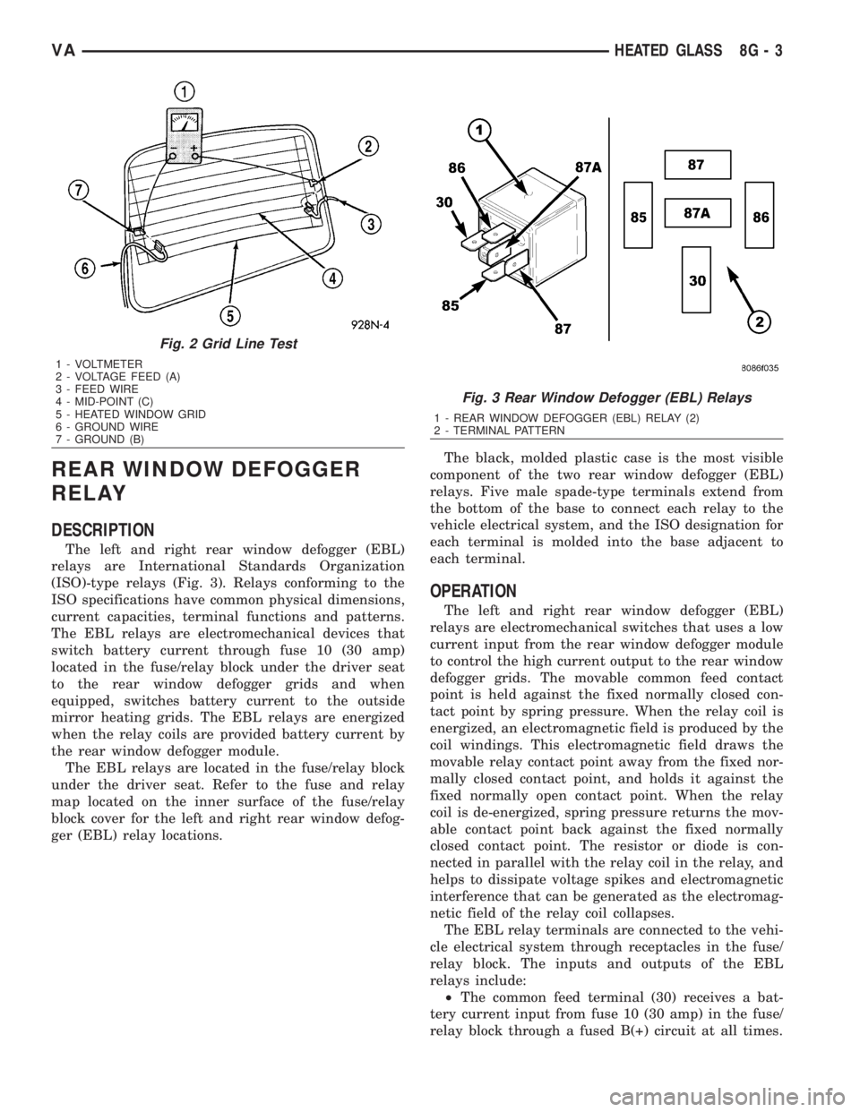
The left and right rear window defogger (EBL)
relays are International Standards Organization
(ISO)-type relays (Fig. 3). Relays conforming to the
ISO specifications have common physical dimensions,
current capacities, terminal functions and patterns.
The EBL relays are electromechanical devices that
switch battery current through fuse 10 (30 amp)
located in the fuse/relay block under the driver seat
to the rear window defogger grids and when
equipped, switches battery current to the outside
mirror heating grids. The EBL relays are energized
when the relay coils are provided battery current by
the rear window defogger module.
The EBL relays are located in the fuse/relay block
under the driver seat. Refer to the fuse and relay
map located on the inner surface of the fuse/relay
block cover for the left and right rear window defog-
ger (EBL) relay locations.The black, molded plastic case is the most visible
component of the two rear window defogger (EBL)
relays. Five male spade-type terminals extend from
the bottom of the base to connect each relay to the
vehicle electrical system, and the ISO designation for
each terminal is molded into the base adjacent to
each terminal.
OPERATION
The left and right rear window defogger (EBL)
relays are electromechanical switches that uses a low
current input from the rear window defogger module
to control the high current output to the rear window
defogger grids. The movable common feed contact
point is held against the fixed normally closed con-
tact point by spring pressure. When the relay coil is
energized, an electromagnetic field is produced by the
coil windings. This electromagnetic field draws the
movable relay contact point away from the fixed nor-
mally closed contact point, and holds it against the
fixed normally open contact point. When the relay
coil is de-energized, spring pressure returns the mov-
able contact point back against the fixed normally
closed contact point. The resistor or diode is con-
nected in parallel with the relay coil in the relay, and
helps to dissipate voltage spikes and electromagnetic
interference that can be generated as the electromag-
netic field of the relay coil collapses.
The EBL relay terminals are connected to the vehi-
cle electrical system through receptacles in the fuse/
relay block. The inputs and outputs of the EBL
relays include:
²The common feed terminal (30) receives a bat-
tery current input from fuse 10 (30 amp) in the fuse/
relay block through a fused B(+) circuit at all times.
Fig. 2 Grid Line Test
1 - VOLTMETER
2 - VOLTAGE FEED (A)
3 - FEED WIRE
4 - MID-POINT (C)
5 - HEATED WINDOW GRID
6 - GROUND WIRE
7 - GROUND (B)
Fig. 3 Rear Window Defogger (EBL) Relays
1 - REAR WINDOW DEFOGGER (EBL) RELAY (2)
2 - TERMINAL PATTERN
VAHEATED GLASS 8G - 3
Page 905 of 2305
²The coil ground terminal (86) is hardwired to
ground point G202.
²The coil battery terminal (85) receives a battery
current input from the rear window defogger module
when the rear window defogger switch is energized.
²The normally open terminal (87) provides a bat-
tery current output to the rear window defogger grid
lines through the relay output circuit only when the
rear window defogger relay coil is energized.
²The normally closed terminal (87A) is not con-
nected to any circuit in this application, but provides
a battery current output only when the rear window
defogger relay coil is de-energized.
The left and right EBL relays cannot be repaired
and, if faulty or damaged, they must be replaced.
Refer to the appropriate wiring information for diag-
nosis and testing of the EBL relays and for complete
rear window defogger system wiring diagrams.
REMOVAL
(1) Disconnect and isolate the negative battery
cable.
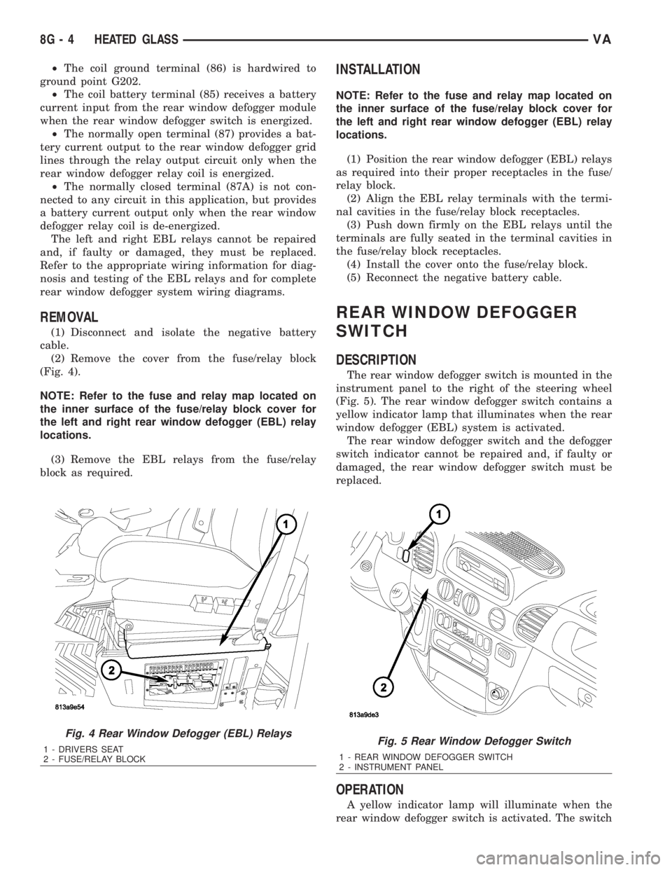
(2) Remove the cover from the fuse/relay block
(Fig. 4).
NOTE: Refer to the fuse and relay map located on
the inner surface of the fuse/relay block cover for
the left and right rear window defogger (EBL) relay
locations.
(3) Remove the EBL relays from the fuse/relay
block as required.
INSTALLATION
NOTE: Refer to the fuse and relay map located on
the inner surface of the fuse/relay block cover for
the left and right rear window defogger (EBL) relay
locations.
(1) Position the rear window defogger (EBL) relays
as required into their proper receptacles in the fuse/
relay block.
(2) Align the EBL relay terminals with the termi-
nal cavities in the fuse/relay block receptacles.
(3) Push down firmly on the EBL relays until the
terminals are fully seated in the terminal cavities in
the fuse/relay block receptacles.
(4) Install the cover onto the fuse/relay block.
(5) Reconnect the negative battery cable.
REAR WINDOW DEFOGGER
SWITCH
DESCRIPTION
The rear window defogger switch is mounted in the
instrument panel to the right of the steering wheel
(Fig. 5). The rear window defogger switch contains a
yellow indicator lamp that illuminates when the rear
window defogger (EBL) system is activated.
The rear window defogger switch and the defogger
switch indicator cannot be repaired and, if faulty or
damaged, the rear window defogger switch must be
replaced.
OPERATION
A yellow indicator lamp will illuminate when the
rear window defogger switch is activated. The switch
Fig. 4 Rear Window Defogger (EBL) Relays
1 - DRIVERS SEAT
2 - FUSE/RELAY BLOCKFig. 5 Rear Window Defogger Switch
1 - REAR WINDOW DEFOGGER SWITCH
2 - INSTRUMENT PANEL
8G - 4 HEATED GLASSVA
Page 906 of 2305
energizes the timing circuit of the rear window defog-
ger module which then activates the rear window
defogger (EBL) relays. The EBL relays controls the
current flow to the rear window defogger grids. The
EBL system will operate for approximately five min-
utes or until the rear window defogger switch or igni-
tion switch is turned off. Refer to 8 - ELECTRICAL/
HEATED GLASS - DIAGNOSIS AND TESTING for
diagnosis and testing of the rear window defogger
switch.
The rear window defogger switch cannot be
repaired and, if faulty or damaged, it must be
replaced.
DIAGNOSIS AND TESTING
REAR WINDOW DEFOGGER SWITCH
WARNING: On vehicles equipped with airbags, dis-
able the airbag system before attempting any steer-
ing wheel, steering column, or instrument panel
component diagnosis or service. Disconnect and
isolate the battery negative (ground) cable, then
wait two minutes for the airbag system capacitor to
discharge before performing further diagnosis or
service. This is the only sure way to disable the air-
bag system. Failure to take the proper precautions
could result in an accidental airbag deployment and
possible personal injury.
NOTE: The rear window defogger switch may be
tested in the vehicle or out of the vehicle, on a
bench.
NOTE: For circuit descriptions and diagrams of the
rear window defogger system, refer to 8W - WIRING
DIAGRAM INFORMATION.
(1) Remove the rear window defogger switch from
the instrument panel, but leave the switch connected
(Refer to 8 - ELECTRICAL/HEATED GLASS/REAR
WINDOW DEFOGGER SWITCH - REMOVAL).
(2) Turn the ignition switch ON.
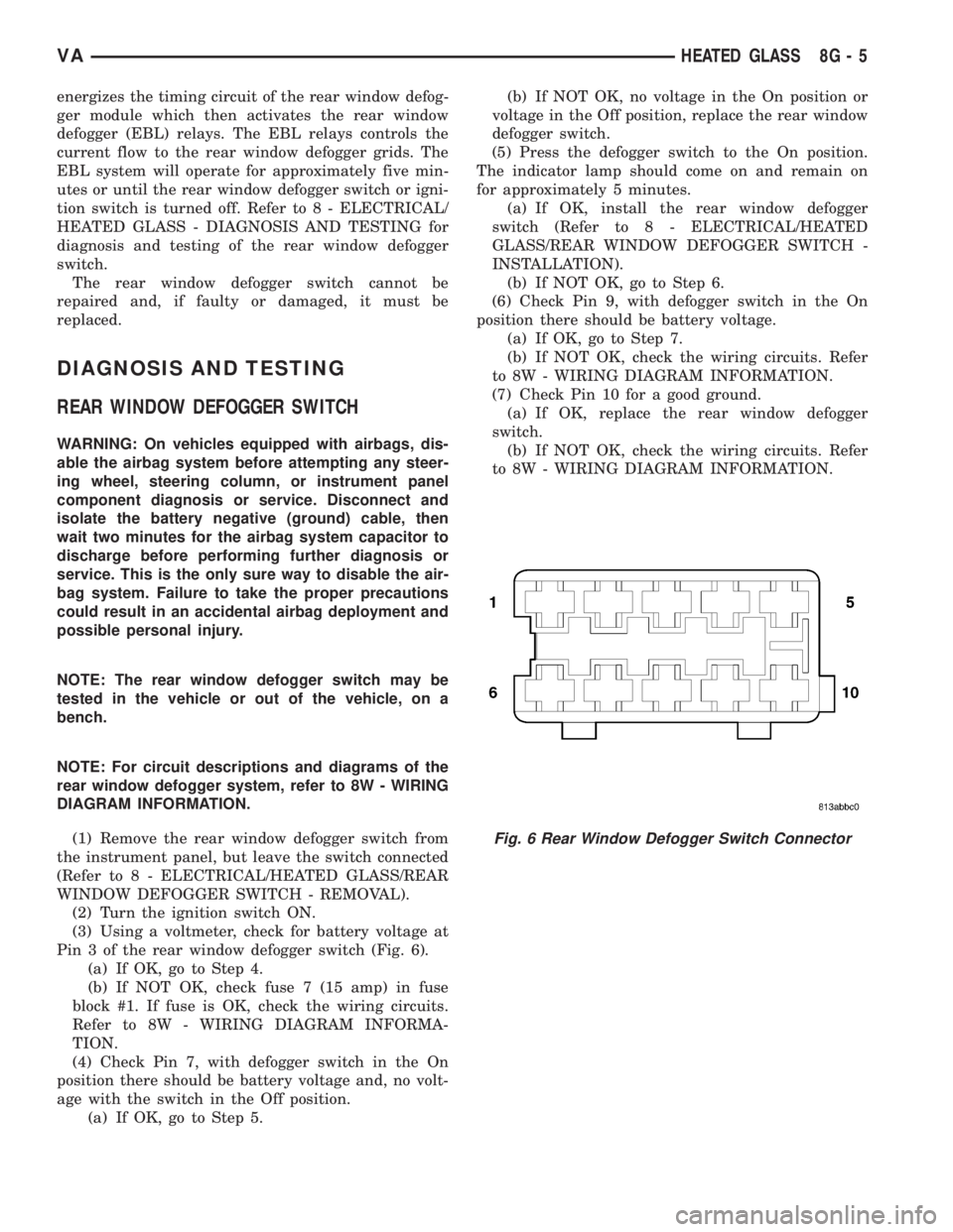
(3) Using a voltmeter, check for battery voltage at
Pin 3 of the rear window defogger switch (Fig. 6).
(a) If OK, go to Step 4.
(b) If NOT OK, check fuse 7 (15 amp) in fuse
block #1. If fuse is OK, check the wiring circuits.
Refer to 8W - WIRING DIAGRAM INFORMA-
TION.
(4) Check Pin 7, with defogger switch in the On
position there should be battery voltage and, no volt-
age with the switch in the Off position.
(a) If OK, go to Step 5.(b) If NOT OK, no voltage in the On position or
voltage in the Off position, replace the rear window
defogger switch.
(5) Press the defogger switch to the On position.
The indicator lamp should come on and remain on
for approximately 5 minutes.
(a) If OK, install the rear window defogger
switch (Refer to 8 - ELECTRICAL/HEATED
GLASS/REAR WINDOW DEFOGGER SWITCH -
INSTALLATION).
(b) If NOT OK, go to Step 6.
(6) Check Pin 9, with defogger switch in the On
position there should be battery voltage.
(a) If OK, go to Step 7.
(b) If NOT OK, check the wiring circuits. Refer
to 8W - WIRING DIAGRAM INFORMATION.
(7) Check Pin 10 for a good ground.
(a) If OK, replace the rear window defogger
switch.
(b) If NOT OK, check the wiring circuits. Refer
to 8W - WIRING DIAGRAM INFORMATION.
Fig. 6 Rear Window Defogger Switch Connector
VAHEATED GLASS 8G - 5
Page 907 of 2305
DEFOGGER SWITCH CONNECTOR PIN
CALL-OUT
PIN FUNCTION
1 FUSED B+ (DRL RELAY)
3 IGNITION SWITCH OUTPUT (START-
RUN)
5 PANEL LAMPS DRIVER
7 DEFOGGER SWITCH OUTPUT
9 PANEL LAMPS DRIVER
10 GROUND
REMOVAL
WARNING: To avoid personal injury or death, on
vehicles equipped with airbags, disable the supple-
mental restraint system before attempting any
steering wheel, steering column, airbag, seat belt
tensioner, or instrument panel component diagno-
sis or service. Disconnect and isolate the battery
negative (ground) cable, then wait two minutes for
the system capacitor to discharge before perform-
ing further diagnosis or service. This is the only
sure way to disable the supplemental restraint sys-
tem. Failure to take the proper precautions could
result in accidental airbag deployment.
(1) Disconnect and isolate the negative battery
cable.
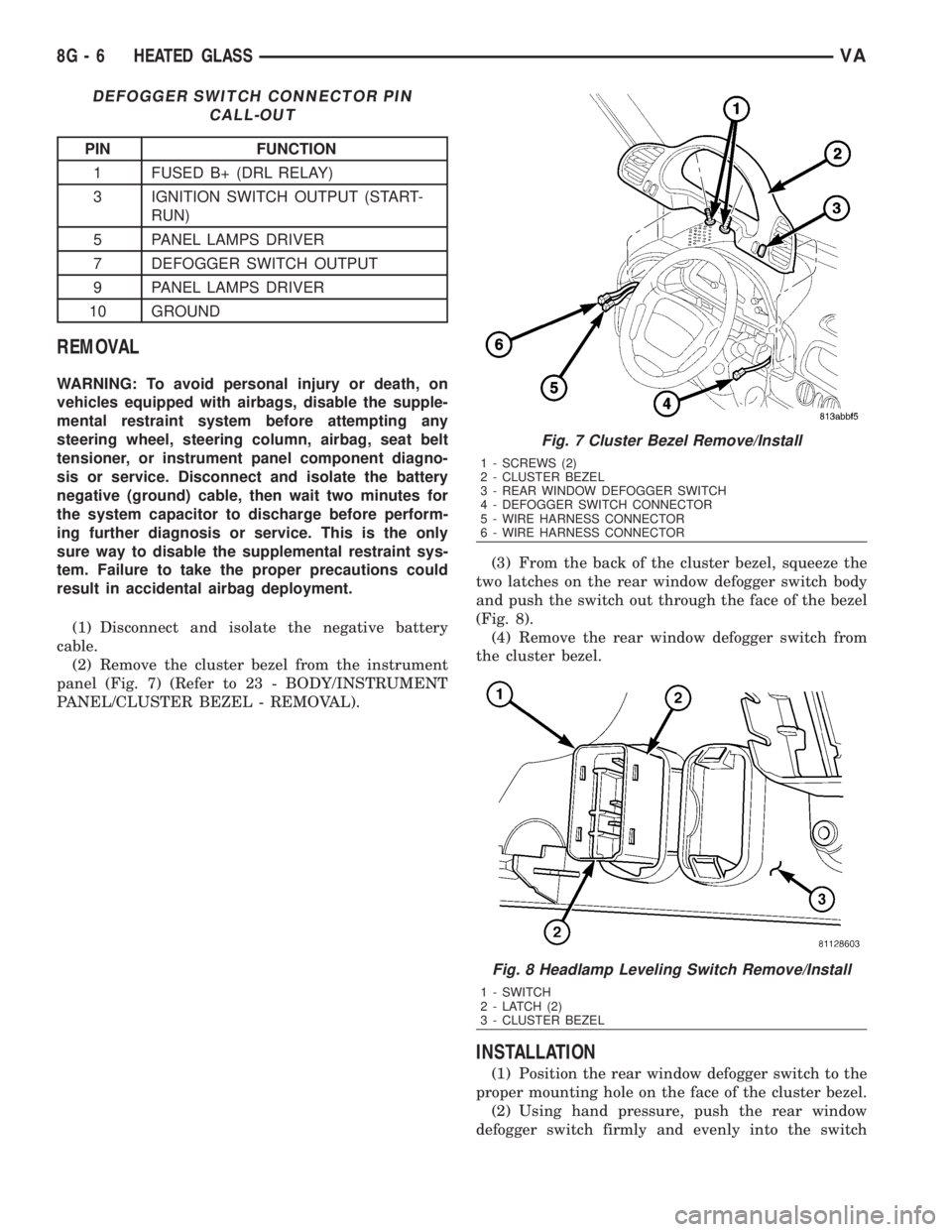
(2) Remove the cluster bezel from the instrument
panel (Fig. 7) (Refer to 23 - BODY/INSTRUMENT
PANEL/CLUSTER BEZEL - REMOVAL).(3) From the back of the cluster bezel, squeeze the
two latches on the rear window defogger switch body
and push the switch out through the face of the bezel
(Fig. 8).
(4) Remove the rear window defogger switch from
the cluster bezel.
INSTALLATION
(1) Position the rear window defogger switch to the
proper mounting hole on the face of the cluster bezel.
(2) Using hand pressure, push the rear window
defogger switch firmly and evenly into the switch
Fig. 7 Cluster Bezel Remove/Install
1 - SCREWS (2)
2 - CLUSTER BEZEL
3 - REAR WINDOW DEFOGGER SWITCH
4 - DEFOGGER SWITCH CONNECTOR
5 - WIRE HARNESS CONNECTOR
6 - WIRE HARNESS CONNECTOR
Fig. 8 Headlamp Leveling Switch Remove/Install
1 - SWITCH
2 - LATCH (2)
3 - CLUSTER BEZEL
8G - 6 HEATED GLASSVA
Page 908 of 2305
mounting hole of the cluster bezel until both of the
latches on the switch body are fully engaged.
(3) Install the cluster bezel (Refer to 23 - BODY/
INSTRUMENT PANEL/CLUSTER BEZEL -
INSTALLATION).
(4) Reconnect the negative battery cable.
REAR WINDOW DEFOGGER
GRID
STANDARD PROCEDURE
GRID LINE AND TERMINAL REPAIR
REAR WINDOW DEFOGGER GRID LINE REPAIR
WARNING: The repair kit contains epoxy resin and
amine type hardener which may cause skin or eye
irritation and can be harmful if swallowed. Use with
adequate ventilation. Do not use near fire or open
flame the contents contain flammable solvents.
Keep out of reach of children.
²DO NOT TAKE INTERNALLY, IF SWALLOWED
INDUCE VOMITING AND CALL A PHYSICIAN IMME-
DIATELY.
²IF SKIN CONTACT OCCURS, WASH AFFECTED
AREAS WITH SOAP AND WATER.
²IF EYE CONTACT OCCURS, FLUSH WITH
PLENTY OF WATER.
The repair of the grid lines is possible using the
MopartGrid Line Repair Package or an equivalent.
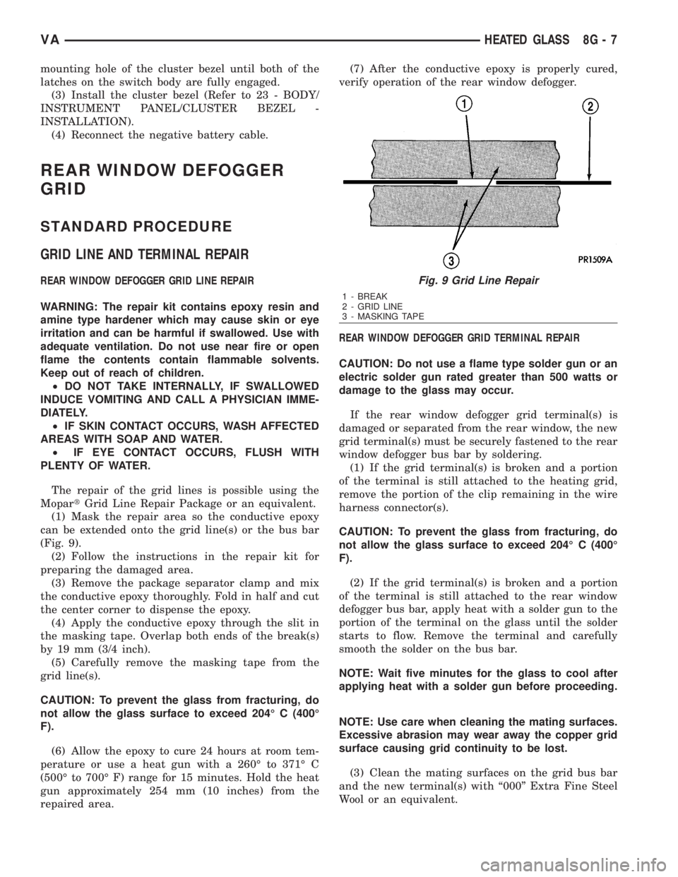
(1) Mask the repair area so the conductive epoxy
can be extended onto the grid line(s) or the bus bar
(Fig. 9).
(2) Follow the instructions in the repair kit for
preparing the damaged area.
(3) Remove the package separator clamp and mix
the conductive epoxy thoroughly. Fold in half and cut
the center corner to dispense the epoxy.
(4) Apply the conductive epoxy through the slit in
the masking tape. Overlap both ends of the break(s)
by 19 mm (3/4 inch).
(5) Carefully remove the masking tape from the
grid line(s).
CAUTION: To prevent the glass from fracturing, do
not allow the glass surface to exceed 204É C (400É
F).
(6) Allow the epoxy to cure 24 hours at room tem-
perature or use a heat gun with a 260É to 371É C
(500É to 700É F) range for 15 minutes. Hold the heat
gun approximately 254 mm (10 inches) from the
repaired area.(7) After the conductive epoxy is properly cured,
verify operation of the rear window defogger.
REAR WINDOW DEFOGGER GRID TERMINAL REPAIR
CAUTION: Do not use a flame type solder gun or an
electric solder gun rated greater than 500 watts or
damage to the glass may occur.
If the rear window defogger grid terminal(s) is
damaged or separated from the rear window, the new
grid terminal(s) must be securely fastened to the rear
window defogger bus bar by soldering.
(1) If the grid terminal(s) is broken and a portion
of the terminal is still attached to the heating grid,
remove the portion of the clip remaining in the wire
harness connector(s).
CAUTION: To prevent the glass from fracturing, do
not allow the glass surface to exceed 204É C (400É
F).
(2) If the grid terminal(s) is broken and a portion
of the terminal is still attached to the rear window
defogger bus bar, apply heat with a solder gun to the
portion of the terminal on the glass until the solder
starts to flow. Remove the terminal and carefully
smooth the solder on the bus bar.
NOTE: Wait five minutes for the glass to cool after
applying heat with a solder gun before proceeding.
NOTE: Use care when cleaning the mating surfaces.
Excessive abrasion may wear away the copper grid
surface causing grid continuity to be lost.
(3) Clean the mating surfaces on the grid bus bar
and the new terminal(s) with ª000º Extra Fine Steel
Wool or an equivalent.Fig. 9 Grid Line Repair
1 - BREAK
2 - GRID LINE
3 - MASKING TAPE
VAHEATED GLASS 8G - 7
Page 909 of 2305
NOTE: The terminal attaching clip(s) must face out-
board. Failure to reorient the terminal(s) may result
in an additional failure.
(4) Properly orient the new terminal(s) with the
attaching clip facing outboard in the original loca-
tion(s) on the grid bus bar and hold the terminal(s)
with a metal pick or other suitable pointed tool.
CAUTION: Do not allow the glass surface to exceed
204É C (400É F), glass may fracture.
NOTE: New rear window defogger terminals are pre-
soldered and fluxed. Do not reuse a terminal if it
has been previously heated.
Place the solder gun onto the new terminal(s) and
heat the terminal until the solder flows. Remove the
solder gun and continue to hold the terminal in the
correct position for an additional five seconds.
(5) Allow the solder to cool for ten minutes.
NOTE: To ensure proper installation, do not attach
the wire harness connector(s) to the terminal(s)
until the solder is completely cooled.
(6) After the solder has cooled, reconnect the wire
harness connector(s) and verify operation of the rear
window defogger.
8G - 8 HEATED GLASSVA
Page 922 of 2305

Located between the rear cover and the cluster
hood is the cluster housing. The molded plastic clus-
ter housing serves as the carrier for the cluster elec-
tronic circuit board and circuitry, the cluster
connector receptacles, the gauges, a Light Emitting
Diode (LED) for each cluster indicator and general
illumination lamp, the multi-function indicator LCD
unit, electronic tone generators, the cluster overlay,
the gauge pointers, the multi-function indicator
switches and the four switch push buttons.
The cluster overlay is a laminated plastic unit. The
dark, visible, outer surface of the overlay is marked
with all of the gauge dial faces and graduations, but
this layer is also translucent. The darkness of this
outer layer prevents the cluster from appearing clut-
tered or busy by concealing the cluster indicators
that are not illuminated, while the translucence of
this layer allows those indicators and icons that are
illuminated to be readily visible. The underlying
layer of the overlay is opaque and allows light from
the LED for each of the various indicators and illu-
mination lamps behind it to be visible through the
outer layer of the overlay only through predeter-
mined cutouts. A rectangular opening in the overlay
at the base of the speedometer provides a window
through which the illuminated multi-function indica-
tor LCD unit can be viewed.
Several versions of the EMIC module are offered
on this model. These versions accommodate all of the
variations of optional equipment and regulatory
requirements for the various markets in which the
vehicle will be offered. The microprocessor-based
EMIC utilizes integrated circuitry, Electrically Eras-
able Programmable Read Only Memory (EEPROM)
type memory storage, information carried on the
Controller Area Network (CAN) data bus, along with
several hard wired analog and multiplexed inputs to
monitor systems, sensors and switches throughout
the vehicle.
In response to those inputs, the hardware and soft-
ware of the EMIC allow it to control and integrate
many electronic functions and features of the vehicle
through both hard wired outputs and the transmis-
sion of electronic message outputs to other electronic
modules in the vehicle over the CAN data bus. (Refer
to 8 - ELECTRICAL/ELECTRONIC CONTROL
MODULES/COMMUNICATION - DESCRIPTION -
CAN BUS).
Besides typical instrument cluster gauge and indi-
cator support, the electronic functions and features
that the EMIC supports or controls include the fol-
lowing:
²Active Service System- In vehicles equipped
with the Active Service SYSTem (ASSYST) engine oil
maintenance indicator option, the EMIC electronic
circuit board includes a second dedicated micropro-
cessor. This second microprocessor evaluates various
data including time, mileage, and driving conditionsto calculate the required engine oil service intervals,
and provides both visual and audible alerts to the
vehicle operator when certain engine oil maintenance
services are required.
²Audible Warnings- The EMIC electronic cir-
cuit board is equipped with an audible tone generator
and programming that allows it to provide various
audible alerts to the vehicle operator, including buzz-
ing and chime tones. An audible contactless elec-
tronic relay is also soldered onto the circuit board to
produce audible clicks that is synchronized with turn
signal indicator flashing to emulate the sounds of a
conventional turn signal or hazard warning flasher.
These audible clicks can occur at one of two rates to
emulate both normal and bulb-out turn or hazard
flasher operation. (Refer to 8 - ELECTRICAL/
CHIME/BUZZER - DESCRIPTION).
²Panel Lamps Dimming Control- The EMIC
provides a hard wired 12-volt Pulse-Width Modulated
(PWM) output that synchronizes the dimming level
of all panel lamps dimmer controlled lamps with that
of the cluster general illumination lamps and multi-
function indicator.
The EMIC houses four analog gauges and has pro-
visions for up to nineteen indicators (Fig. 3). The
EMIC includes the following analog gauges:
²Coolant Temperature Gauge
²Fuel Gauge
²Speedometer
²Tachometer
The EMIC includes provisions for the following
indicators (Fig. 3):
²Airbag (SRS) Indicator
²Antilock Brake System (ABS) Indicator
²Brake Indicator
²Brake Wear Indicator
²Charging Indicator
²Clogged Fuel Filter Indicator
²Constant Engine Speed (ADR) Indicator
²Coolant Low Indicator
²Electronic Stability Program (ESP) Indica-
tor
²High Beam Indicator
²Low Fuel Indicator
²Malfunction Indicator Lamp (MIL)
²Multi-Function Indicator (LCD)
²Park Brake Indicator
²Seatbelt Indicator
²Traction Control (ASR) Indicator
²Traction Control (ASR) Malfunction Indica-
tor
²Turn Signal (Right and Left) Indicators
²Washer Fluid Indicator
²Wait-To-Start Indicator
²Water-In-Fuel Indicator
VAINSTRUMENT CLUSTER 8J - 3
Page 961 of 2305
(3) Remove the cover panel from the top of the
driver side seat riser.
(4) Remove the fog lamp relay by grasping it
firmly and pulling it straight out of the relay connec-
tor.
INSTALLATION
Fog lamps are optional equipment on this model.
On vehicles equipped with fog lamps, a fog lamp
relay is located in a dedicated connector of the vehi-
cle wire harness. This connector is snapped into an
opening in a stamped sheet metal bracket which is
secured with screws within the driver side front seat
riser just beneath the seat riser cover panel.
WARNING: To avoid personal injury or death, on
vehicles equipped with airbags, disable the supple-
mental restraint system before attempting any
steering wheel, steering column, airbag, seat belt
tensioner, or instrument panel component diagno-
sis or service. Disconnect and isolate the battery
negative (ground) cable, then wait two minutes for
the system capacitor to discharge before perform-
ing further diagnosis or service. This is the only
sure way to disable the supplemental restraint sys-
tem. Failure to take the proper precautions could
result in accidental airbag deployment.
(1) Position the fog lamp relay to the relay connec-
tor.
(2) Align the fog lamp relay terminals with the
terminal cavities in the relay connector.
(3) Using hand pressure, push firmly and evenly
on the top of the fog lamp relay until the terminals
are fully seated in the relay connector.
(4) Position the cover panel onto the top of the
driver side seat riser (Fig. 15).(5) Install and tighten the two screws that secure
the cover panel to the top of the seat riser under the
driver side front seat.
(6) Move the driver side front seat back to its driv-
ing position.
(7) Reconnect the battery negative cable.
FOG LAMP SWITCH
REMOVAL
WARNING: To avoid personal injury or death, on
vehicles equipped with airbags, disable the supple-
mental restraint system before attempting any
steering wheel, steering column, airbag, seat belt
tensioner, or instrument panel component diagno-
sis or service. Disconnect and isolate the battery
negative (ground) cable, then wait two minutes for
the system capacitor to discharge before perform-
ing further diagnosis or service. This is the only
sure way to disable the supplemental restraint sys-
tem. Failure to take the proper precautions could
result in accidental airbag deployment.
(1) Disconnect and isolate the battery negative
cable.
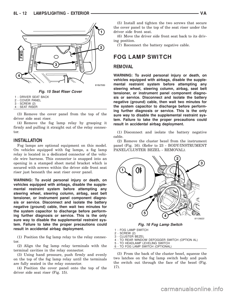
(2) Remove the cluster bezel from the instrument
panel (Fig. 16). (Refer to 23 - BODY/INSTRUMENT
PANEL/CLUSTER BEZEL - REMOVAL).
(3) From the back of the cluster bezel, squeeze the
two latches on the fog lamp switch body and push
the switch out through the face of the bezel (Fig.
17).
Fig. 15 Seat Riser Cover
1 - DRIVER SEAT BACK
2 - COVER PANEL
3 - SCREW (2)
4 - SEAT RISER
Fig. 16 Fog Lamp Switch
1 - FOG LAMP SWITCH
2 - SCREW (2)
3 - CLUSTER BEZEL
4 - TO REAR WINDOW DEFOGGER SWITCH (OPTION AL)
5 - TO HEADLAMP LEVELING SWITCH
6 - TO FOG LAMP SWITCH (OPTIONAL)
8L - 12 LAMPS/LIGHTING - EXTERIORVA