2006 MERCEDES-BENZ SPRINTER keyless
[x] Cancel search: keylessPage 6 of 2305
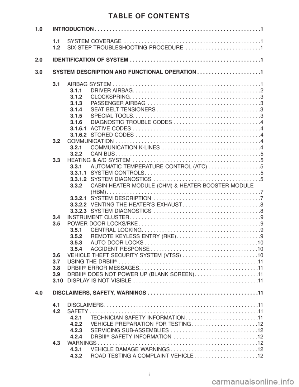
TABLE OF CONTENTS
1.0 INTRODUCTION.........................................................1
1.1SYSTEM COVERAGE...............................................1
1.2SIX-STEP TROUBLESHOOTING PROCEDURE..........................1
2.0 IDENTIFICATION OF SYSTEM.............................................1
3.0 SYSTEM DESCRIPTION AND FUNCTIONAL OPERATION......................1
3.1AIRBAG SYSTEM...................................................1
3.1.1DRIVER AIRBAG............................................2
3.1.2CLOCKSPRING.............................................3
3.1.3PASSENGER AIRBAG.......................................3
3.1.4SEAT BELT TENSIONERS....................................3
3.1.5SPECIAL TOOLS............................................3
3.1.6DIAGNOSTIC TROUBLE CODES..............................4
3.1.6.1ACTIVE CODES............................................4
3.1.6.2STORED CODES...........................................4
3.2COMMUNICATION..................................................4
3.2.1COMMUNICATION K-LINES..................................4
3.2.2CAN BUS..................................................5
3.3HEATING & A/C SYSTEM............................................5
3.3.1AUTOMATIC TEMPERATURE CONTROL (ATC)..................5
3.3.1.1SYSTEM CONTROLS........................................5
3.3.1.2SYSTEM DIAGNOSTICS.....................................5
3.3.2CABIN HEATER MODULE (CHM) & HEATER BOOSTER MODULE
(HBM).....................................................7
3.3.2.1SYSTEM DESCRIPTION.....................................7
3.3.2.2VENTING THE HEATER'S EXHAUST...........................8
3.3.2.3SYSTEM DIAGNOSTICS.....................................8
3.4INSTRUMENT CLUSTER.............................................9
3.5POWER DOOR LOCKS/RKE..........................................9
3.5.1CENTRAL LOCKING.........................................9
3.5.2REMOTE KEYLESS ENTRY (RKE).............................9
3.5.3AUTO DOOR LOCKS.......................................10
3.5.4ACCIDENT RESPONSE.....................................10
3.6VEHICLE THEFT SECURITY SYSTEM (VTSS)..........................10
3.7USING THE DRBIIIT................................................11
3.8DRBIIITERROR MESSAGES.........................................11
3.9DRBIIITDOES NOT POWER UP (BLANK SCREEN)......................11
3.10DISPLAY IS NOT VISIBLE...........................................11
4.0 DISCLAIMERS, SAFETY, WARNINGS......................................11
4.1DISCLAIMERS.....................................................11
4.2SAFETY..........................................................11
4.2.1TECHNICIAN SAFETY INFORMATION.........................11
4.2.2VEHICLE PREPARATION FOR TESTING.......................12
4.2.3SERVICING SUB-ASSEMBLIES..............................12
4.2.4DRBIIITSAFETY INFORMATION.............................12
4.3WARNINGS.......................................................12
4.3.1VEHICLE DAMAGE WARNINGS..............................12
4.3.2ROAD TESTING A COMPLAINT VEHICLE......................12
i
Page 12 of 2305

TABLE OF CONTENTS - Continued
FUSES (FUSE BLOCK NO. 2)............................................274
FUSES (FUSE BLOCK NO. 3)............................................276
FUSES (FUSE/RELAY BLOCK)...........................................278
HOOD AJAR SWITCH - BLACK...........................................278
HORN (VTSS).........................................................278
IGNITION LOCK SWITCH - BLACK........................................278
INSTRUMENT CLUSTER C1.............................................279
INSTRUMENT CLUSTER C2 - WHITE.....................................279
INTRUSION SENSOR NO. 1 - BLACK.....................................279
INTRUSION SENSOR NO. 2 - BLACK.....................................279
INTRUSION SENSOR NO. 3 - BLACK.....................................280
MASTER DOOR LOCK SWITCH..........................................280
PANIC ALARM SWITCH - BLACK.........................................280
FUSES (PDC).........................................................281
RADIO C1 - BLACK....................................................282
RADIO C2............................................................282
RECIRCULATED AIR SOLENOID VALVE...................................282
REFRIGERANT PRESSURE SENSOR.....................................282
A/C AUXILIARY FAN RELAY (RELAY BLOCK)...............................284
CIRCULATION PUMP RELAY-CABIN HEATER MODULE (RELAY BLOCK).......284
D+ RELAY NO. 2 (RELAY BLOCK)........................................284
FAN STAGE 1 RELAY (RELAY BLOCK)....................................284
OPTIONAL EQUIPMENT RELAY (RELAY BLOCK)...........................284
REMOTE KEYLESS ENTRY ANTENNA....................................284
SEAT BELT SWITCH...................................................284
SEAT BELT TENSIONER-DRIVER - YELLOW...............................285
SEAT BELT TENSIONER-PASSENGER - YELLOW...........................285
SECURITY SYSTEM MODULE C1 - BROWN...............................285
SECURITY SYSTEM MODULE C2 - LT. GREEN.............................286
SENTRY KEY REMOTE ENTRY MODULE (SKREEM)........................286
SHIFTER ASSEMBLY - BLACK...........................................286
SIREN - BLACK.......................................................286
STEERING ANGLE SENSOR............................................287
TOWING/INTRUSION SENSOR ON/OFF SWITCH...........................287
TRANSMISSION CONTROL MODULE C1 - BLACK..........................287
TRANSMISSION CONTROL MODULE C2 - BLACK..........................288
WATER CYCLE VALVE..................................................288
WINDOW DEFOGGER-LEFT REAR.......................................288
WINDOW DEFOGGER-RIGHT REAR......................................288
10.0 SCHEMATIC DIAGRAMS................................................289
10.1AIRBAG SYSTEM.................................................289
10.2COMMUNICATION................................................290
10.2.1COMMUNICATION K-LINES................................290
10.2.2CAN BUS NETWORK......................................291
10.3HEATING & A/C...................................................292
10.3.1AUTOMATIC TEMPERATURE CONTROL (ATC)................292
10.3.2CABIN HEATER MODULE (CHM)............................293
10.3.3HEATER BOOSTER MODULE (HBM).........................294
10.4INSTRUMENT CLUSTER...........................................295
vii
Page 22 of 2305
Static Heater Signal
A status of9ON9indicates that the heater module
sees the9Stationary Heating Mode ON9signal after
switching on the heater with the heater timer or the
auxiliary heater switch. A status of9OFF9indicates
that the9Stationary Heating Mode ON9signal is
not present at the heater module.
Heater Booster Mode Signal
A status of9ON9indicates that the heater module
sees the9Heater Booster Mode ON9signal after
switching on the heater with the auxiliary heater
switch. A status of9OFF9indicates that the9Heater
Booster Mode ON9signal is not present at the
heater module.
3.4 INSTRUMENT CLUSTER
The Instrument Cluster has easy-to-read instru-
ments, is capable of CAN bus communication and
provides a diagnostic function. The Instrument
Cluster with analog speedometer, tachometer, fuel
and coolant temperature gauges comes in two ver-
sions.
²Speedometer with outer miles-per-hour (mph)
scale and inner kilometers-per-hour (km/h) scale.
Coolant temperature is indicated in Fahrenheit
(for US).
²Speedometer with outer kilometers-per-hour
(km/h) scale and inner miles-per-hours (mph)
scale. Coolant temperature is indicated in de-
grees Celsius (for Canada).
Below the speedometer, there is a LCD multi-
function indicator in clear view of the driver. Warn-
ing and indicator lights (based on colored light
emitting diodes) are located in the bottom of the
instrument cluster with the exception of the turn
signal indicator lights, ASR warning light and re-
serve fuel warning light. The warning lights for the
seat belt usage and parking brake/brake fluid level
are located in the line above the bottom line. The
indicator that illuminates up when the parking
brake is applied or the brake fluid level is low is
different for U.S. and Canada.
When the key is turned to the 2nd position in the
ignition, the function of the following indicator
lights is checked automatically: High Beam ON,
Preheating, airbag malfunction. In case of a broken
LED of the airbag malfunction light, the seat belt
usage warning light will flash for 6 seconds after
the function check is finished. The Instrument
Cluster is operated with the help of 4 buttons
located below the multifunction indicator. The back-
lighting for the instrument cluster uses yellow
LED's and can be adjusted electronically to daylight
and darkness.The instrument cluster includes a warning
buzzer, which sounds (in addition to a warning light
in some cases) when:
²The headlights are on with the ignition off and
the door opened.
²The driver 's seat belt is not fastened with the
ignition on.
²The key is in the ignition and the door is open.
²Critical ASSYST information is displayed in the
multifunction indicator.
3.5 POWER DOOR LOCKS/RKE
3.5.1 CENTRAL LOCKING
The Central Locking System locks all vehicle
doors if any door is locked from the inside or
mechanically locked with the key from the outside.
However, unlocking any door, in that manner, will
only unlock that particular door. The Master Door
Lock Switch on the dash enables the operator to
lock/unlock all doors. By pressing the top of the
rocker type switch once, all doors will lock. Pressing
the switch again will unlock all doors. Pressing the
lower part of the switch once will lock all doors
except the driver door. Pressing the lower part
again will unlock all doors except the driver door. If
the Central Locking System automatically unlocks
after the vehicle was attempted to be locked, at
least one door is not properly closed.
There are two LED indicators in the Master Door
Lock Switch. The left indicator is for the driver door
and the right indicator is for all passenger/cargo
doors. These will indicate if a door is ajar or if the
doors are locked. The door ajar switches are part of
the door lock motor and are mounted in the door
latch assembly.
Inside each door lock motor there is a command
switch. The command switch is operated by the
plunger and signals any change in the lock status,
locked or unlocked. Each command switch is wired
to the Central Timer Module (CTM) sometimes
referred to as the Central Locking Module. If all
doors are closed and are unlocked, and any door is
locked by the key or the interior handle, thereby
changing the command switch, all doors will be
locked. If one of the door lock motors does not reach
the end position after a locking command, it will be
detected by the CTM (command switch not in
9Locked9position) and the vehicle will be unlocked.
3.5.2 REMOTE KEYLESS ENTRY (RKE)
The SKREEM is a combination of the Remote
Keyless Entry Module and the SKIM (Sentry Key
Immobilizer Module). It is located behind the In-
strument Cluster and has an antenna that goes up
9
GENERAL INFORMATION
Page 297 of 2305
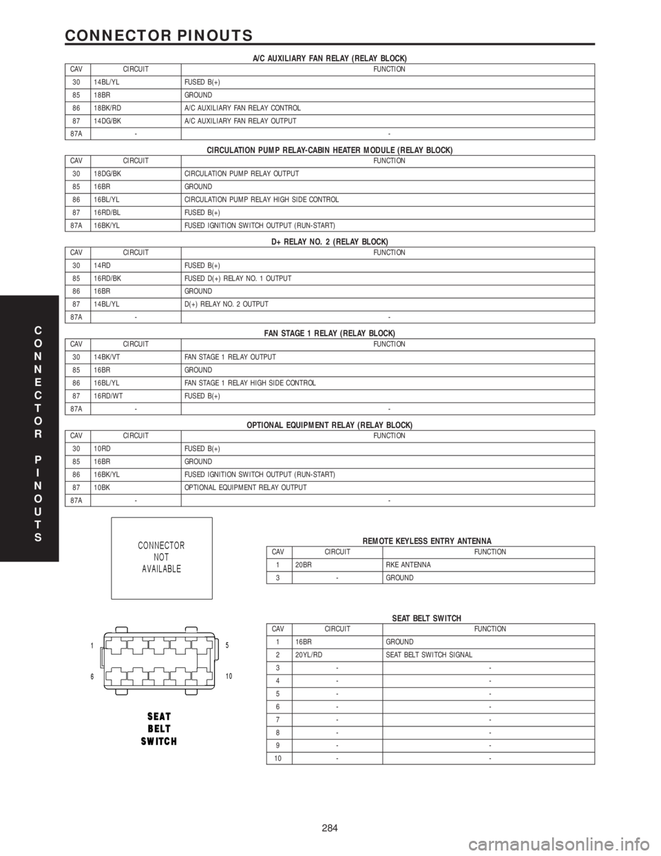
A/C AUXILIARY FAN RELAY (RELAY BLOCK)CAV CIRCUIT FUNCTION
30 14BL/YL FUSED B(+)
85 18BR GROUND
86 18BK/RD A/C AUXILIARY FAN RELAY CONTROL
87 14DG/BK A/C AUXILIARY FAN RELAY OUTPUT
87A --
CIRCULATION PUMP RELAY-CABIN HEATER MODULE (RELAY BLOCK)CAV CIRCUIT FUNCTION
30 18DG/BK CIRCULATION PUMP RELAY OUTPUT
85 16BR GROUND
86 16BL/YL CIRCULATION PUMP RELAY HIGH SIDE CONTROL
87 16RD/BL FUSED B(+)
87A 16BK/YL FUSED IGNITION SWITCH OUTPUT (RUN-START)
D+ RELAY NO. 2 (RELAY BLOCK)CAV CIRCUIT FUNCTION
30 14RD FUSED B(+)
85 16RD/BK FUSED D(+) RELAY NO. 1 OUTPUT
86 16BR GROUND
87 14BL/YL D(+) RELAY NO. 2 OUTPUT
87A --
FAN STAGE 1 RELAY (RELAY BLOCK)CAV CIRCUIT FUNCTION
30 14BK/VT FAN STAGE 1 RELAY OUTPUT
85 16BR GROUND
86 16BL/YL FAN STAGE 1 RELAY HIGH SIDE CONTROL
87 16RD/WT FUSED B(+)
87A --
OPTIONAL EQUIPMENT RELAY (RELAY BLOCK)CAV CIRCUIT FUNCTION
30 10RD FUSED B(+)
85 16BR GROUND
86 16BK/YL FUSED IGNITION SWITCH OUTPUT (RUN-START)
87 10BK OPTIONAL EQUIPMENT RELAY OUTPUT
87A --
REMOTE KEYLESS ENTRY ANTENNACAV CIRCUIT FUNCTION
1 20BR RKE ANTENNA
3 - GROUND
SEAT BELT SWITCHCAV CIRCUIT FUNCTION
1 16BR GROUND
2 20YL/RD SEAT BELT SWITCH SIGNAL
3- -
4- -
5- -
6- -
7- -
8- -
9- -
10 - -
C
O
N
N
E
C
T
O
R
P
I
N
O
U
T
S
284
CONNECTOR PINOUTS
Page 856 of 2305

ELECTRONIC CONTROL MODULES
TABLE OF CONTENTS
page page
CENTRAL TIMER MODULE
DESCRIPTION..........................1
OPERATION............................1
DIAGNOSIS AND TESTING - CENTRAL TIMER
MODULE.............................2
REMOVAL.............................2
INSTALLATION..........................3
CONTROLLER ANTILOCK BRAKE
DESCRIPTION..........................3
REMOVAL.............................3INSTALLATION..........................3
ENGINE CONTROL MODULE
DESCRIPTION..........................3
REMOVAL.............................6
INSTALLATION..........................6
TRANSMISSION CONTROL MODULE
DESCRIPTION..........................6
OPERATION............................7
STANDARD PROCEDURE - TCM ADAPTATION . 10
CENTRAL TIMER MODULE
DESCRIPTION
The central timer module (CTM) is located beneath
the driver seat. The CTM uses information carried on
the programmable communications interface (PCI)
data bus network along with many hard wired inputs
to monitor many sensor and switch inputs. In
response to those inputs, the circuitry and program-
ming of the CTM allow it to supply the vehicle occu-
pants with audible and visual information, and to
control and integrate many functions and features of
the vehicle through both hard wired outputs and the
transmission of message outputs to other modules in
the vehicle over the PCI data bus.
The features that the CTM supports or controls
include the following:
²Central Locking- The CTM on vehicles
equipped with the optional Vehicle Theft Security
System (VTSS) includes a central locking/unlocking
feature.
²Enhanced Accident Response- The CTM pro-
vides an optional enhanced accident response fea-
ture. This is a programmable feature.
²Panic Mode- The CTM provides support for
the optional RKE system panic mode including horn,
headlamp, and park lamp flash features.
²Power Lock Control- The CTM provides the
optional power lock system features, including sup-
port for the automatic door lock and door lock inhibit
modes.
²Programmable Features- The CTM provides
support for certain programmable features.
²Remote Keyless Entry- The CTM provides
the optional Remote Keyless Entry (RKE) system fea-
tures, including support for the RKE Lock (with
optional horn and park lamps flash), Unlock (with
park lamps flash, driver-door-only unlock, andunlock-all-doors), Panic, and illuminated entry
modes, as well as the ability to be programmed to
recognize up to four RKE transmitters. The RKE
horn, driver-door-only unlock, and unlock-all-doors
features are programmable.
²Vehicle Theft Security System- The CTM
provides control of the optional Vehicle Theft Secu-
rity System (VTSS) features, including support for
the central locking/unlocking mode and control of the
Security indicator in the instrument cluster.
Hard wired circuitry connects the CTM to the elec-
trical system of the vehicle. Refer to the appropriate
wiring information.
Many of the features in the vehicle controlled or
supported by the CTM are programmable using the
DRBIIItscan tool. However, if any of the CTM hard-
ware components are damaged or faulty, the entire
CTM unit must be replaced. The hard wired inputs
or outputs of all CTM versions can be diagnosed
using conventional diagnostic tools and methods;
however, for diagnosis of the CTM or the PCI data
bus, the use of a DRBIIItscan tool is required. Refer
to the appropriate diagnostic information.
OPERATION
The central timer module (CTM) monitors many
hard wired switch and sensor inputs as well as those
resources it shares with other modules in the vehicle
through its communication over the programmable
communications interface (PCI) data bus network.
The internal programming and all of these inputs
allow the CTM to determine the tasks it needs to
perform and their priorities, as well as both the stan-
dard and optional features that it should provide.
The CTM then performs those tasks and provides
those features through both PCI data bus communi-
cation with other modules and hard wired outputs
through a number of driver circuits, relays, and
VAELECTRONIC CONTROL MODULES 8E - 1
Page 921 of 2305
INSTRUMENT CLUSTER
DESCRIPTION
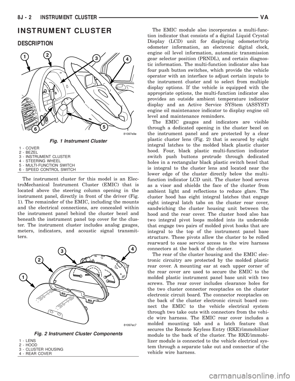
The instrument cluster for this model is an Elec-
troMechanical Instrument Cluster (EMIC) that is
located above the steering column opening in the
instrument panel, directly in front of the driver (Fig.
1). The remainder of the EMIC, including the mounts
and the electrical connections, are concealed within
the instrument panel behind the cluster bezel and
beneath the instrument panel top cover for the clus-
ter. The instrument cluster includes analog gauges,
meters, indicators, and acoustic signal transmit-
ters.The EMIC module also incorporates a multi-func-
tion indicator that consists of a digital Liquid Crystal
Display (LCD) unit for displaying odometer/trip
odometer information, an electronic digital clock,
engine oil level information, automatic transmission
gear selector position (PRNDL), and certain diagnos-
tic information. The multi-function indicator also has
four push button switches, which provide the vehicle
operator with an interface to adjust certain inputs to
the instrument cluster and to select from multiple
display options. If the vehicle is equipped with the
appropriate options, the multi-function indicator also
provides an outside ambient temperature indicator
display and an Active Service SYStem (ASSYST)
engine oil maintenance indicator to display engine oil
level and maintenance reminders.
The EMIC gauges and indicators are visible
through a dedicated opening in the cluster bezel on
the instrument panel and are protected by a clear
plastic cluster lens (Fig. 2) that is secured by eight
integral latches to the molded black plastic cluster
hood. Four, black plastic multi-function indicator
switch push buttons protrude through dedicated
holes in a rectangular black plastic switch bezel that
is integral to the cluster lens and located near the
lower edge of the cluster directly below the multi-
function indicator LCD unit. The cluster hood serves
as a visor and shields the face of the cluster from
ambient light and reflections to reduce glare. The
cluster hood has eight integral latches that engage
eight integral latch tabs on the cluster rear cover,
sandwiching the cluster housing unit between the
hood and the rear cover. The cluster hood also has
two integral pivot loops molded into its underside
that engage two pairs of molded pivot hooks that are
integral to the top of the instrument panel base
structure. These pivots allow the cluster to be rolled
rearward to ease service access to the wire harness
connectors at the back of the cluster.
The rear of the cluster housing and the EMIC elec-
tronic circuitry are protected by the molded plastic
rear cover. A mounting ear at each upper corner of
the rear cover are used to secure the EMIC to the
molded plastic instrument panel base unit with two
screws. The rear cover includes clearance holes for
the two cluster connector receptacles on the cluster
electronic circuit board. The connector receptacles on
the back of the cluster electronic circuit board con-
nect the EMIC to the vehicle electrical system
through two take outs with connectors from the vehi-
cle wire harness. The EMIC rear cover includes a
molded mounting tab and a latch feature that
secures the Remote Keyless Entry (RKE)/immobilizer
module to the back of the cluster. The RKE/immobi-
lizer module is connected to the vehicle electrical sys-
tem through a separate take out and connector of the
vehicle wire harness.
Fig. 1 Instrument Cluster
1 - COVER
2 - BEZEL
3 - INSTRUMENT CLUSTER
4 - STEERING WHEEL
5 - MULTI-FUNCTION SWITCH
6 - SPEED CONTROL SWITCH
Fig. 2 Instrument Cluster Components
1 - LENS
2 - HOOD
3 - CLUSTER HOUSING
4 - REAR COVER
8J - 2 INSTRUMENT CLUSTERVA
Page 927 of 2305
NOTE: Mileage will not be displayed until the IC has
been locked down.
REMOVAL
WARNING: To avoid personal injury or death, on
vehicles equipped with airbags, disable the supple-
mental restraint system before attempting any
steering wheel, steering column, airbag, seat belt
tensioner, or instrument panel component diagno-
sis or service. Disconnect and isolate the battery
negative (ground) cable, then wait two minutes for
the system capacitor to discharge before perform-
ing further diagnosis or service. This is the only
sure way to disable the supplemental restraint sys-
tem. Failure to take the proper precautions could
result in accidental airbag deployment.
CAUTION: The following procedure is for replace-
ment of an ineffective and unresponsive Instrument
Cluster (IC) with a new unit. If the IC is ineffective
or damaged but still responsive, it may be replaced
using an automatic replacement procedure that will
upload IC parameterization data from the existing IC
to the diagnostic scan tool, then download that data
to the new IC. Refer to the MISCELLANEOUS FUNC-
TIONS menu item under the IC module in the diag-
nostic scan tool, then select MODULE AUTO
REPLACEMENT and follow the scan tool prompts to
replace the IC. Do not lock down the IC until all of
the steps are followed and completed or the new IC
may be irreversibly damaged. This procedure initial-
izes and configures the IC for certain optional
equipment on the vehicle without the need for per-
forming a separate cluster programming procedure.
Failure to correctly parameterize the IC prior to it
being electronically locked down will result in the
IC being incorrectly and irreversibly configured for
improper vehicle equipment options, which will
require the IC be replaced again with another new
and unused unit to resolve.
(1) Disconnect and isolate the battery negative
cable.
(2) Remove the cluster bezel from the instrument
panel. (Refer to 23 - BODY/INSTRUMENT PANEL/
CLUSTER BEZEL - REMOVAL).
(3) Remove the cluster top cover from the instru-
ment panel. (Refer to 23 - BODY/INSTRUMENT
PANEL/TOP COVER - CLUSTER - REMOVAL).
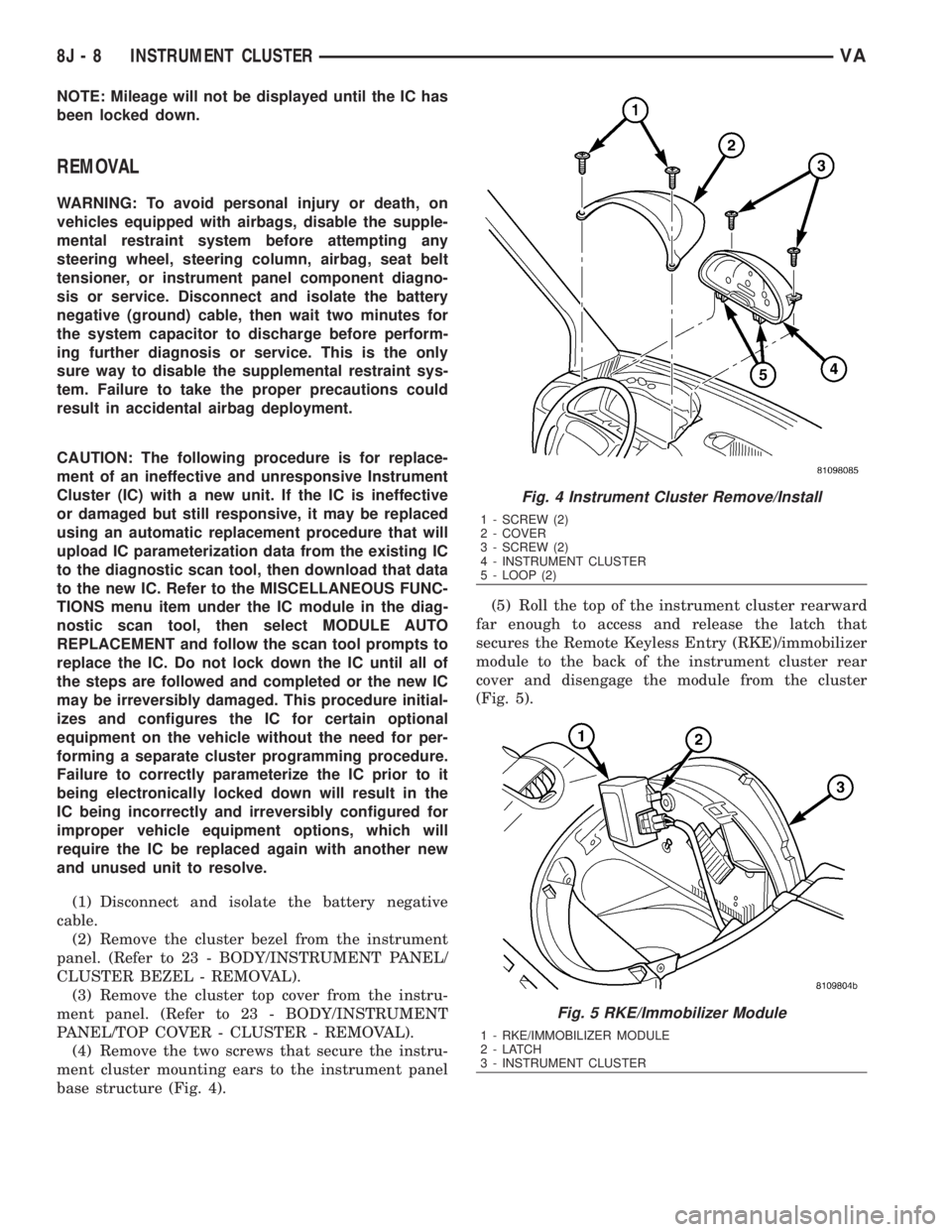
(4) Remove the two screws that secure the instru-
ment cluster mounting ears to the instrument panel
base structure (Fig. 4).(5) Roll the top of the instrument cluster rearward
far enough to access and release the latch that
secures the Remote Keyless Entry (RKE)/immobilizer
module to the back of the instrument cluster rear
cover and disengage the module from the cluster
(Fig. 5).
Fig. 4 Instrument Cluster Remove/Install
1 - SCREW (2)
2 - COVER
3 - SCREW (2)
4 - INSTRUMENT CLUSTER
5 - LOOP (2)
Fig. 5 RKE/Immobilizer Module
1 - RKE/IMMOBILIZER MODULE
2-LATCH
3 - INSTRUMENT CLUSTER
8J - 8 INSTRUMENT CLUSTERVA
Page 928 of 2305
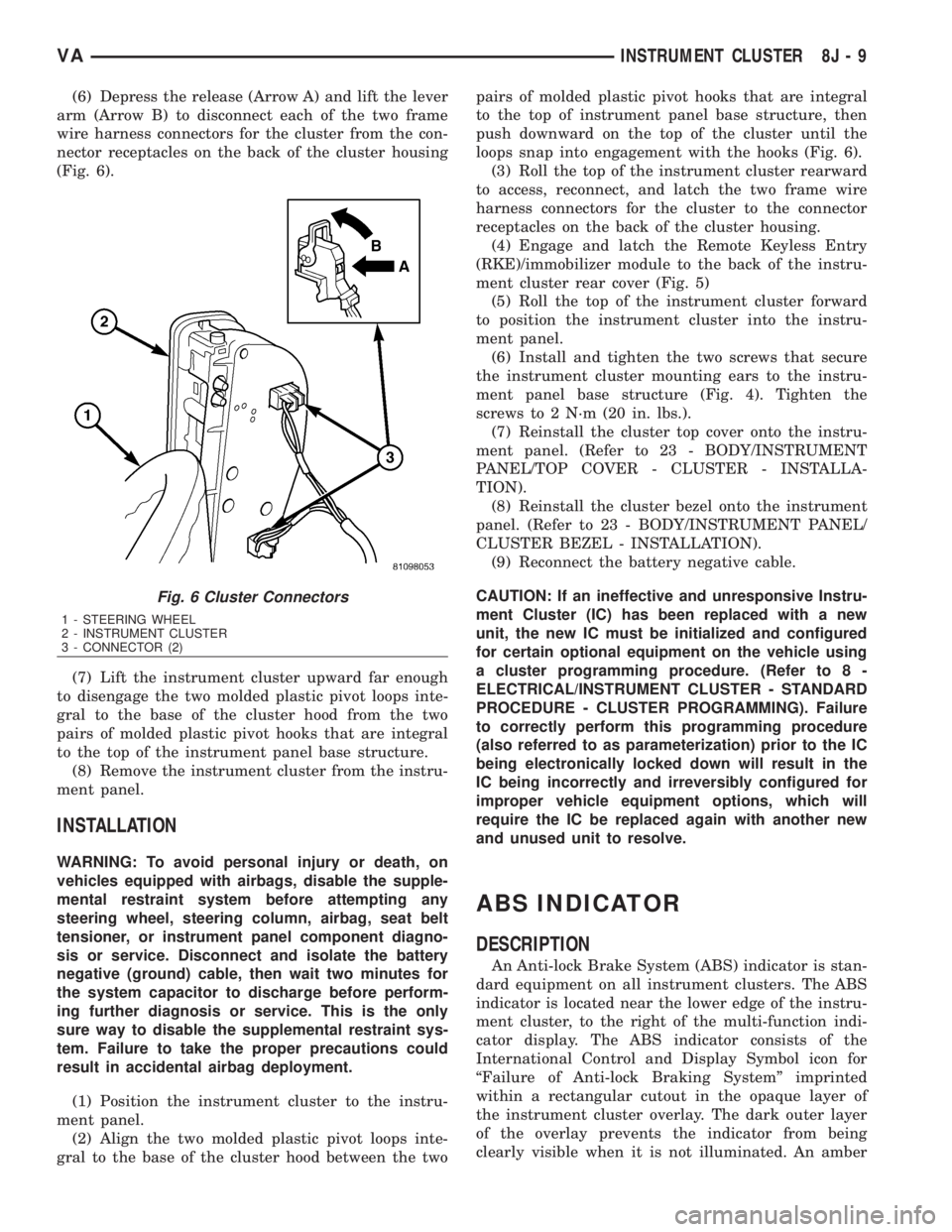
(6) Depress the release (Arrow A) and lift the lever
arm (Arrow B) to disconnect each of the two frame
wire harness connectors for the cluster from the con-
nector receptacles on the back of the cluster housing
(Fig. 6).
(7) Lift the instrument cluster upward far enough
to disengage the two molded plastic pivot loops inte-
gral to the base of the cluster hood from the two
pairs of molded plastic pivot hooks that are integral
to the top of the instrument panel base structure.
(8) Remove the instrument cluster from the instru-
ment panel.
INSTALLATION
WARNING: To avoid personal injury or death, on
vehicles equipped with airbags, disable the supple-
mental restraint system before attempting any
steering wheel, steering column, airbag, seat belt
tensioner, or instrument panel component diagno-
sis or service. Disconnect and isolate the battery
negative (ground) cable, then wait two minutes for
the system capacitor to discharge before perform-
ing further diagnosis or service. This is the only
sure way to disable the supplemental restraint sys-
tem. Failure to take the proper precautions could
result in accidental airbag deployment.
(1) Position the instrument cluster to the instru-
ment panel.
(2) Align the two molded plastic pivot loops inte-
gral to the base of the cluster hood between the twopairs of molded plastic pivot hooks that are integral
to the top of instrument panel base structure, then
push downward on the top of the cluster until the
loops snap into engagement with the hooks (Fig. 6).
(3) Roll the top of the instrument cluster rearward
to access, reconnect, and latch the two frame wire
harness connectors for the cluster to the connector
receptacles on the back of the cluster housing.
(4) Engage and latch the Remote Keyless Entry
(RKE)/immobilizer module to the back of the instru-
ment cluster rear cover (Fig. 5)
(5) Roll the top of the instrument cluster forward
to position the instrument cluster into the instru-
ment panel.
(6) Install and tighten the two screws that secure
the instrument cluster mounting ears to the instru-
ment panel base structure (Fig. 4). Tighten the
screws to 2 N´m (20 in. lbs.).
(7) Reinstall the cluster top cover onto the instru-
ment panel. (Refer to 23 - BODY/INSTRUMENT
PANEL/TOP COVER - CLUSTER - INSTALLA-
TION).
(8) Reinstall the cluster bezel onto the instrument
panel. (Refer to 23 - BODY/INSTRUMENT PANEL/
CLUSTER BEZEL - INSTALLATION).
(9) Reconnect the battery negative cable.
CAUTION: If an ineffective and unresponsive Instru-
ment Cluster (IC) has been replaced with a new
unit, the new IC must be initialized and configured
for certain optional equipment on the vehicle using
a cluster programming procedure. (Refer to 8 -
ELECTRICAL/INSTRUMENT CLUSTER - STANDARD
PROCEDURE - CLUSTER PROGRAMMING). Failure
to correctly perform this programming procedure
(also referred to as parameterization) prior to the IC
being electronically locked down will result in the
IC being incorrectly and irreversibly configured for
improper vehicle equipment options, which will
require the IC be replaced again with another new
and unused unit to resolve.
ABS INDICATOR
DESCRIPTION
An Anti-lock Brake System (ABS) indicator is stan-
dard equipment on all instrument clusters. The ABS
indicator is located near the lower edge of the instru-
ment cluster, to the right of the multi-function indi-
cator display. The ABS indicator consists of the
International Control and Display Symbol icon for
ªFailure of Anti-lock Braking Systemº imprinted
within a rectangular cutout in the opaque layer of
the instrument cluster overlay. The dark outer layer
of the overlay prevents the indicator from being
clearly visible when it is not illuminated. An amber
Fig. 6 Cluster Connectors
1 - STEERING WHEEL
2 - INSTRUMENT CLUSTER
3 - CONNECTOR (2)
VAINSTRUMENT CLUSTER 8J - 9