2006 MERCEDES-BENZ SPRINTER keyless
[x] Cancel search: keylessPage 986 of 2305
POWER SYSTEMS
TABLE OF CONTENTS
page page
POWER LOCKS............................ 1
POWER MIRRORS......................... 3POWER WINDOWS......................... 5
POWER LOCKS
TABLE OF CONTENTS
page page
DOOR LOCK MOTOR
REMOVAL.............................1
INSTALLATION..........................1
REMOTE KEYLESS ENTRY TRANSMITTER
DESCRIPTION..........................1
MASTER LOCK SWITCH
DESCRIPTION..........................1DIAGNOSIS AND TESTING - MASTER LOCK
SWITCH.............................1
REMOVAL.............................2
INSTALLATION..........................2
DOOR LOCK MOTOR
REMOVAL
(1) Disconnect and isolate the battery negative
cable.
(2) Remove the door trim panel.
(3) Remove the door lock.
(4) Remove the door lock motor from the door lock.
INSTALLATION
(1) Install the door lock motor to the door lock.
(2) Install the door lock.
(3) Install the door trim panel.
(4) Connect the battery negative cable.
REMOTE KEYLESS ENTRY
TRANSMITTER
DESCRIPTION
Pressing the unlock button on the transmitter will
unlock the drivers door, pressing it a second time
within 2.5 seconds will unlock all other doors. The
transmitter has a range of 10 meters. A key is inte-
gral to the transmitter.
When a transmitter is lost, it is necessary to dis-
able the affected transmitter so that it can no longer
be used to operate the vehicle. It will then be neces-
sary to program a new transmitter to the vehicle.
MASTER LOCK SWITCH
DESCRIPTION
The master lock switch is a momentary contact
switch. Pressing the once in the up direction unlocks
the driver door. Pressing it again in the same direc-
tion unlocks all doors. Pressing the button in the
down direction locks all doors.
DIAGNOSIS AND TESTING - MASTER LOCK
SWITCH
(1) Disconnect and isolate the battery negative
cable.
(2) Remove the switch to be tested.
(3) Using an ohmmeter, test switch for continuity
(Fig. 1).
(4) If test results are not obtained as shown in the
test table, replace the switch.
VAPOWER SYSTEMS 8N - 1
Page 1039 of 2305
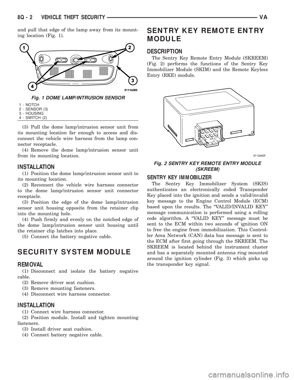
and pull that edge of the lamp away from its mount-
ing location (Fig. 1).
(3) Pull the dome lamp/intrusion sensor unit from
its mounting location far enough to access and dis-
connect the vehicle wire harness from the lamp con-
nector receptacle.
(4) Remove the dome lamp/intrusion sensor unit
from its mounting location.
INSTALLATION
(1) Position the dome lamp/intrusion sensor unit to
its mounting location.
(2) Reconnect the vehicle wire harness connector
to the dome lamp/intrusion sensor unit connector
receptacle.
(3) Position the edge of the dome lamp/intrusion
sensor unit housing opposite from the retainer clip
into the mounting hole.
(4) Push firmly and evenly on the notched edge of
the dome lamp/intrusion sensor unit housing until
the retainer clip latches into place.
(5) Connect the battery negative cable.
SECURITY SYSTEM MODULE
REMOVAL
(1) Disconnect and isolate the battery negative
cable.
(2) Remove driver seat cushion.
(3) Remove mounting fasteners.
(4) Disconnect wire harness connector.
INSTALLATION
(1) Connect wire harness connector.
(2) Position module. Install and tighten mounting
fasteners.
(3) Install driver seat cushion.
(4) Connect battery negative cable.
SENTRY KEY REMOTE ENTRY
MODULE
DESCRIPTION
The Sentry Key Remote Entry Module (SKREEM)
(Fig. 2) performs the functions of the Sentry Key
Immobilizer Module (SKIM) and the Remote Keyless
Entry (RKE) module.
SENTRY KEY IMMOBILIZER
The Sentry Key Immobilizer System (SKIS)
authenticates an electronically coded Transponder
Key placed into the ignition and sends a valid/invalid
key message to the Engine Control Module (ECM)
based upon the results. The ªVALID/INVALID KEYº
message communication is performed using a rolling
code algorithm. A ªVALID KEYº message must be
sent to the ECM within two seconds of ignition ON
to free the engine from immobilization. This Control-
ler Area Network (CAN) data bus message is sent to
the ECM after first going through the SKREEM. The
SKREEM is located behind the instrument cluster
and has a separately mounted antenna ring mounted
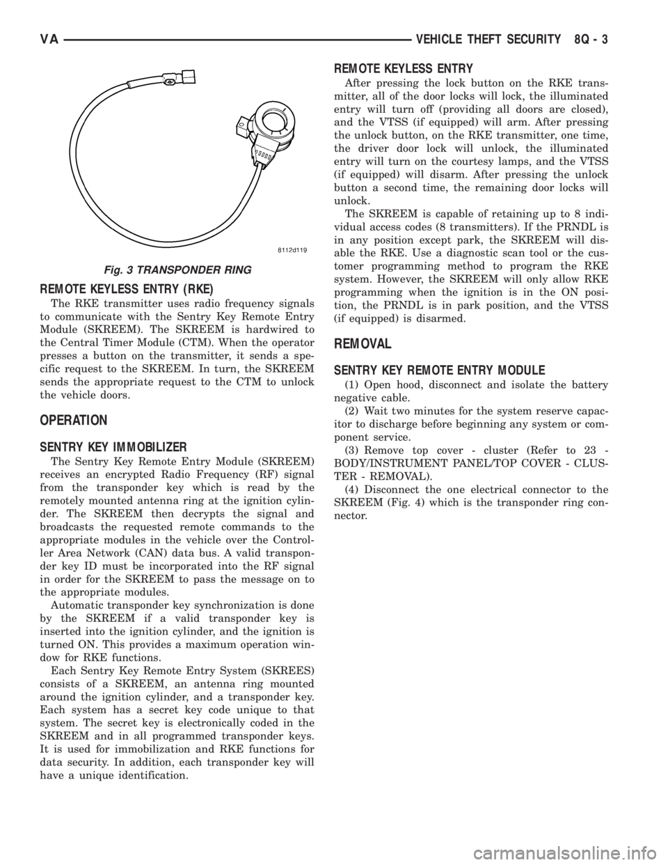
around the ignition cylinder (Fig. 3) which picks up
the transponder key signal.
Fig. 1 DOME LAMP/INTRUSION SENSOR
1 - NOTCH
2 - SENSOR (3)
3 - HOUSING
4 - SWITCH (2)
Fig. 2 SENTRY KEY REMOTE ENTRY MODULE
(SKREEM)
8Q - 2 VEHICLE THEFT SECURITYVA
Page 1040 of 2305
REMOTE KEYLESS ENTRY (RKE)
The RKE transmitter uses radio frequency signals
to communicate with the Sentry Key Remote Entry
Module (SKREEM). The SKREEM is hardwired to
the Central Timer Module (CTM). When the operator
presses a button on the transmitter, it sends a spe-
cific request to the SKREEM. In turn, the SKREEM
sends the appropriate request to the CTM to unlock
the vehicle doors.
OPERATION
SENTRY KEY IMMOBILIZER
The Sentry Key Remote Entry Module (SKREEM)
receives an encrypted Radio Frequency (RF) signal
from the transponder key which is read by the
remotely mounted antenna ring at the ignition cylin-
der. The SKREEM then decrypts the signal and
broadcasts the requested remote commands to the
appropriate modules in the vehicle over the Control-
ler Area Network (CAN) data bus. A valid transpon-
der key ID must be incorporated into the RF signal
in order for the SKREEM to pass the message on to
the appropriate modules.
Automatic transponder key synchronization is done
by the SKREEM if a valid transponder key is
inserted into the ignition cylinder, and the ignition is
turned ON. This provides a maximum operation win-
dow for RKE functions.
Each Sentry Key Remote Entry System (SKREES)
consists of a SKREEM, an antenna ring mounted
around the ignition cylinder, and a transponder key.
Each system has a secret key code unique to that
system. The secret key is electronically coded in the
SKREEM and in all programmed transponder keys.
It is used for immobilization and RKE functions for
data security. In addition, each transponder key will
have a unique identification.
REMOTE KEYLESS ENTRY
After pressing the lock button on the RKE trans-
mitter, all of the door locks will lock, the illuminated
entry will turn off (providing all doors are closed),
and the VTSS (if equipped) will arm. After pressing
the unlock button, on the RKE transmitter, one time,
the driver door lock will unlock, the illuminated
entry will turn on the courtesy lamps, and the VTSS
(if equipped) will disarm. After pressing the unlock
button a second time, the remaining door locks will
unlock.
The SKREEM is capable of retaining up to 8 indi-
vidual access codes (8 transmitters). If the PRNDL is
in any position except park, the SKREEM will dis-
able the RKE. Use a diagnostic scan tool or the cus-
tomer programming method to program the RKE
system. However, the SKREEM will only allow RKE
programming when the ignition is in the ON posi-
tion, the PRNDL is in park position, and the VTSS
(if equipped) is disarmed.
REMOVAL
SENTRY KEY REMOTE ENTRY MODULE
(1) Open hood, disconnect and isolate the battery
negative cable.
(2) Wait two minutes for the system reserve capac-
itor to discharge before beginning any system or com-
ponent service.
(3) Remove top cover - cluster (Refer to 23 -
BODY/INSTRUMENT PANEL/TOP COVER - CLUS-
TER - REMOVAL).
(4) Disconnect the one electrical connector to the
SKREEM (Fig. 4) which is the transponder ring con-
nector.
Fig. 3 TRANSPONDER RING
VAVEHICLE THEFT SECURITY 8Q - 3
Page 1042 of 2305
TRANSPONDER KEY
DESCRIPTION
The Sentry Key Immobilizer System (SKIS) which
communicates with the Sentry Key Remote Entry
Module (SKREEM), uses a transponder chip that is
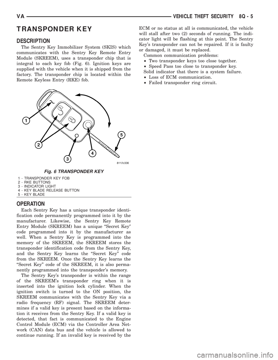
integral to each key fob (Fig. 6). Ignition keys are
supplied with the vehicle when it is shipped from the
factory. The transponder chip is located within the
Remote Keyless Entry (RKE) fob.
OPERATION
Each Sentry Key has a unique transponder identi-
fication code permanently programmed into it by the
manufacturer. Likewise, the Sentry Key Remote
Entry Module (SKREEM) has a unique ªSecret Key9
code programmed into it by the manufacturer as
well. When a Sentry Key is programmed into the
memory of the SKREEM, the SKREEM stores the
transponder identification code from the Sentry Key,
and the Sentry Key learns the ªSecret Keyº code
from the SKREEM. Once the Sentry Key learns the
ªSecret Keyº code of the SKREEM, it is also perma-
nently programmed into the transponder's memory.
The Sentry Key's transponder is within the range
of the SKREEM's transponder ring when it is
inserted into the ignition lock cylinder. When the
ignition switch is turned to the ON position, the
SKREEM communicates with the Sentry Key via a
radio frequency (RF) signal. The SKREEM deter-
mines if a valid key is present based on the informa-
tion it receives from the Sentry Key. If a valid key is
detected, that fact is communicated to the Engine
Control Module (ECM) via the Controller Area Net-
work (CAN) data bus and the vehicle is allowed to
continue running. If an invalid key is received by theECM or no status at all is communicated, the vehicle
will stall after two (2) seconds of running. The indi-
cator light will be flashing at this point. The Sentry
Key's transponder can not be repaired. If it is faulty
or damaged, it must be replaced.
Common communication problems:
²Two transponder keys too close together.
²Speed Pass too close to transponder key.
Solid indicator that there is a system failure.
²Loss of ECM communication.
²Failed transponder ring circuit.
Fig. 6 TRANSPONDER KEY
1 - TRANSPONDER KEY FOB
2 - RKE BUTTONS
3 - INDICATOR LIGHT
4 - KEY BLADE RELEASE BUTTON
5 - KEY BLADE
VAVEHICLE THEFT SECURITY 8Q - 5
Page 1420 of 2305
Component Page
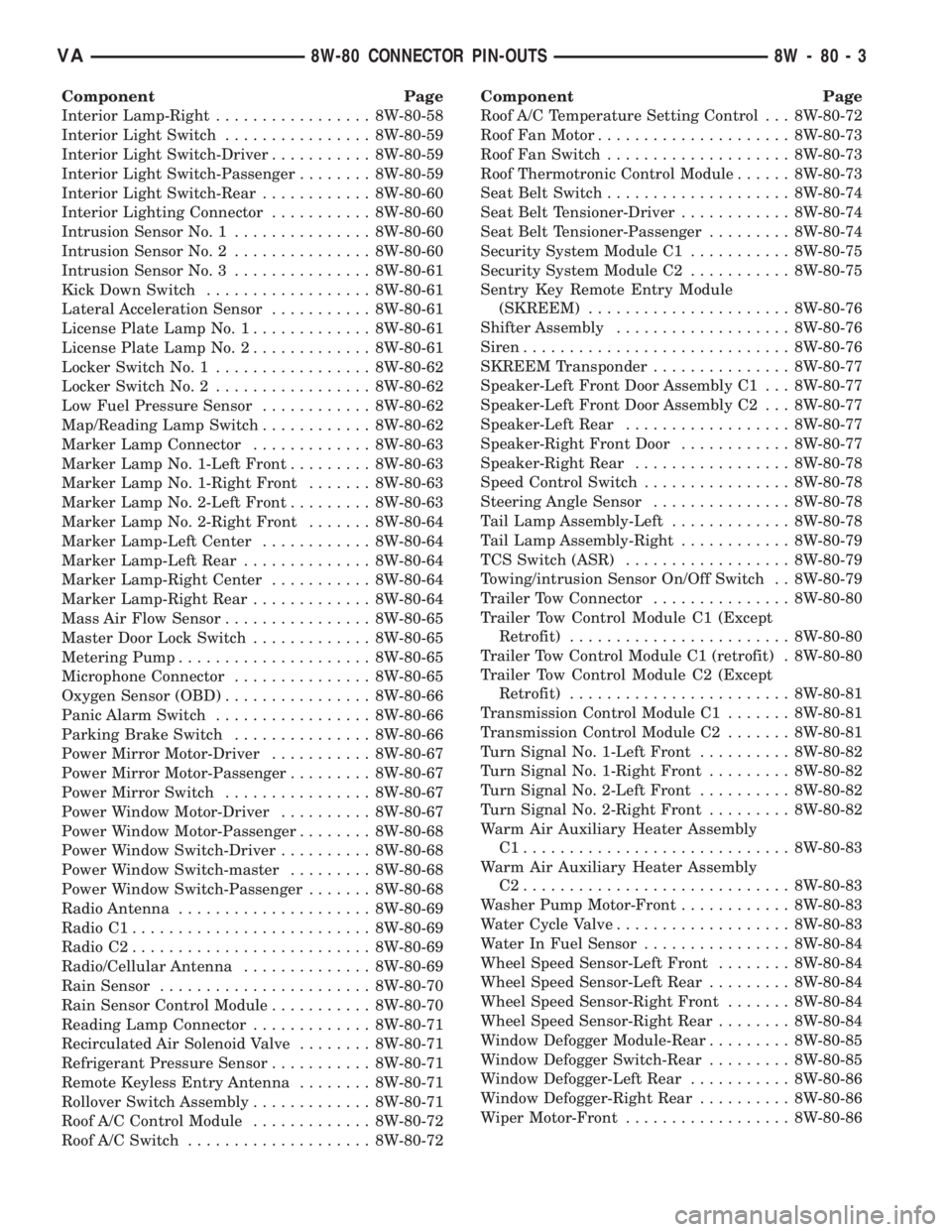
Interior Lamp-Right................. 8W-80-58
Interior Light Switch................ 8W-80-59
Interior Light Switch-Driver........... 8W-80-59
Interior Light Switch-Passenger........ 8W-80-59
Interior Light Switch-Rear............ 8W-80-60
Interior Lighting Connector........... 8W-80-60
Intrusion Sensor No. 1............... 8W-80-60
Intrusion Sensor No. 2............... 8W-80-60
Intrusion Sensor No. 3............... 8W-80-61
Kick Down Switch.................. 8W-80-61
Lateral Acceleration Sensor........... 8W-80-61
License Plate Lamp No. 1............. 8W-80-61
License Plate Lamp No. 2............. 8W-80-61
Locker Switch No. 1................. 8W-80-62
Locker Switch No. 2................. 8W-80-62
Low Fuel Pressure Sensor............ 8W-80-62
Map/Reading Lamp Switch............ 8W-80-62
Marker Lamp Connector............. 8W-80-63
Marker Lamp No. 1-Left Front......... 8W-80-63
Marker Lamp No. 1-Right Front....... 8W-80-63
Marker Lamp No. 2-Left Front......... 8W-80-63
Marker Lamp No. 2-Right Front....... 8W-80-64
Marker Lamp-Left Center............ 8W-80-64
Marker Lamp-Left Rear.............. 8W-80-64
Marker Lamp-Right Center........... 8W-80-64
Marker Lamp-Right Rear............. 8W-80-64
Mass Air Flow Sensor................ 8W-80-65
Master Door Lock Switch............. 8W-80-65
Metering Pump..................... 8W-80-65
Microphone Connector............... 8W-80-65
Oxygen Sensor (OBD)................ 8W-80-66
Panic Alarm Switch................. 8W-80-66
Parking Brake Switch............... 8W-80-66
Power Mirror Motor-Driver........... 8W-80-67
Power Mirror Motor-Passenger......... 8W-80-67
Power Mirror Switch................ 8W-80-67
Power Window Motor-Driver.......... 8W-80-67
Power Window Motor-Passenger........ 8W-80-68
Power Window Switch-Driver.......... 8W-80-68
Power Window Switch-master......... 8W-80-68
Power Window Switch-Passenger....... 8W-80-68
Radio Antenna..................... 8W-80-69
Radio C1.......................... 8W-80-69
Radio C2.......................... 8W-80-69
Radio/Cellular Antenna.............. 8W-80-69
Rain Sensor....................... 8W-80-70
Rain Sensor Control Module........... 8W-80-70
Reading Lamp Connector............. 8W-80-71
Recirculated Air Solenoid Valve........ 8W-80-71
Refrigerant Pressure Sensor........... 8W-80-71
Remote Keyless Entry Antenna........ 8W-80-71
Rollover Switch Assembly............. 8W-80-71
Roof A/C Control Module............. 8W-80-72
Roof A/C Switch.................... 8W-80-72Component Page
Roof A/C Temperature Setting Control . . . 8W-80-72
Roof Fan Motor..................... 8W-80-73
Roof Fan Switch.................... 8W-80-73
Roof Thermotronic Control Module...... 8W-80-73
Seat Belt Switch.................... 8W-80-74
Seat Belt Tensioner-Driver............ 8W-80-74
Seat Belt Tensioner-Passenger......... 8W-80-74
Security System Module C1........... 8W-80-75
Security System Module C2........... 8W-80-75
Sentry Key Remote Entry Module
(SKREEM)...................... 8W-80-76
Shifter Assembly................... 8W-80-76
Siren............................. 8W-80-76
SKREEM Transponder............... 8W-80-77
Speaker-Left Front Door Assembly C1 . . . 8W-80-77
Speaker-Left Front Door Assembly C2 . . . 8W-80-77
Speaker-Left Rear.................. 8W-80-77
Speaker-Right Front Door............ 8W-80-77
Speaker-Right Rear................. 8W-80-78
Speed Control Switch................ 8W-80-78
Steering Angle Sensor............... 8W-80-78
Tail Lamp Assembly-Left............. 8W-80-78
Tail Lamp Assembly-Right............ 8W-80-79
TCS Switch (ASR).................. 8W-80-79
Towing/intrusion Sensor On/Off Switch . . 8W-80-79
Trailer Tow Connector............... 8W-80-80
Trailer Tow Control Module C1 (Except
Retrofit)........................ 8W-80-80
Trailer Tow Control Module C1 (retrofit) . 8W-80-80
Trailer Tow Control Module C2 (Except
Retrofit)........................ 8W-80-81
Transmission Control Module C1....... 8W-80-81
Transmission Control Module C2....... 8W-80-81
Turn Signal No. 1-Left Front.......... 8W-80-82
Turn Signal No. 1-Right Front......... 8W-80-82
Turn Signal No. 2-Left Front.......... 8W-80-82
Turn Signal No. 2-Right Front......... 8W-80-82
Warm Air Auxiliary Heater Assembly
C1............................. 8W-80-83
Warm Air Auxiliary Heater Assembly
C2............................. 8W-80-83
Washer Pump Motor-Front............ 8W-80-83
Water Cycle Valve................... 8W-80-83
Water In Fuel Sensor................ 8W-80-84
Wheel Speed Sensor-Left Front........ 8W-80-84
Wheel Speed Sensor-Left Rear......... 8W-80-84
Wheel Speed Sensor-Right Front....... 8W-80-84
Wheel Speed Sensor-Right Rear........ 8W-80-84
Window Defogger Module-Rear......... 8W-80-85
Window Defogger Switch-Rear......... 8W-80-85
Window Defogger-Left Rear........... 8W-80-86
Window Defogger-Right Rear.......... 8W-80-86
Wiper Motor-Front.................. 8W-80-86
VA8W-80 CONNECTOR PIN-OUTS 8W - 80 - 3
Page 1488 of 2305
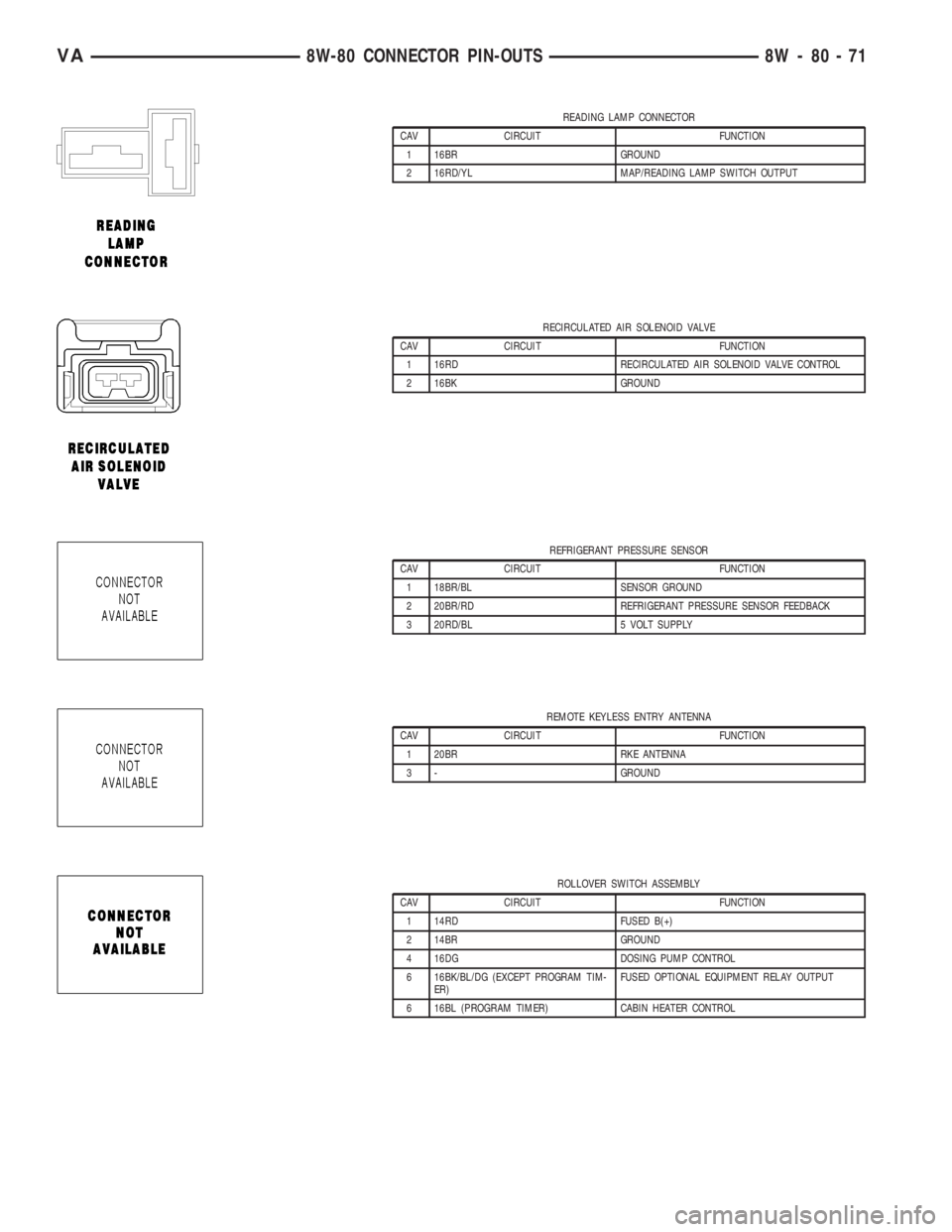
READING LAMP CONNECTOR
CAV CIRCUIT FUNCTION
1 16BR GROUND
2 16RD/YL MAP/READING LAMP SWITCH OUTPUT
RECIRCULATED AIR SOLENOID VALVE
CAV CIRCUIT FUNCTION
1 16RD RECIRCULATED AIR SOLENOID VALVE CONTROL
2 16BK GROUND
REFRIGERANT PRESSURE SENSOR
CAV CIRCUIT FUNCTION
1 18BR/BL SENSOR GROUND
2 20BR/RD REFRIGERANT PRESSURE SENSOR FEEDBACK
3 20RD/BL 5 VOLT SUPPLY
REMOTE KEYLESS ENTRY ANTENNA
CAV CIRCUIT FUNCTION
1 20BR RKE ANTENNA
3 - GROUND
ROLLOVER SWITCH ASSEMBLY
CAV CIRCUIT FUNCTION
1 14RD FUSED B(+)
2 14BR GROUND
4 16DG DOSING PUMP CONTROL
6 16BK/BL/DG (EXCEPT PROGRAM TIM-
ER)FUSED OPTIONAL EQUIPMENT RELAY OUTPUT
6 16BL (PROGRAM TIMER) CABIN HEATER CONTROL
VA8W-80 CONNECTOR PIN-OUTS 8W - 80 - 71
Page 1511 of 2305
CONNECTOR NAME/NUMBER COLOR LOCATION FIG.
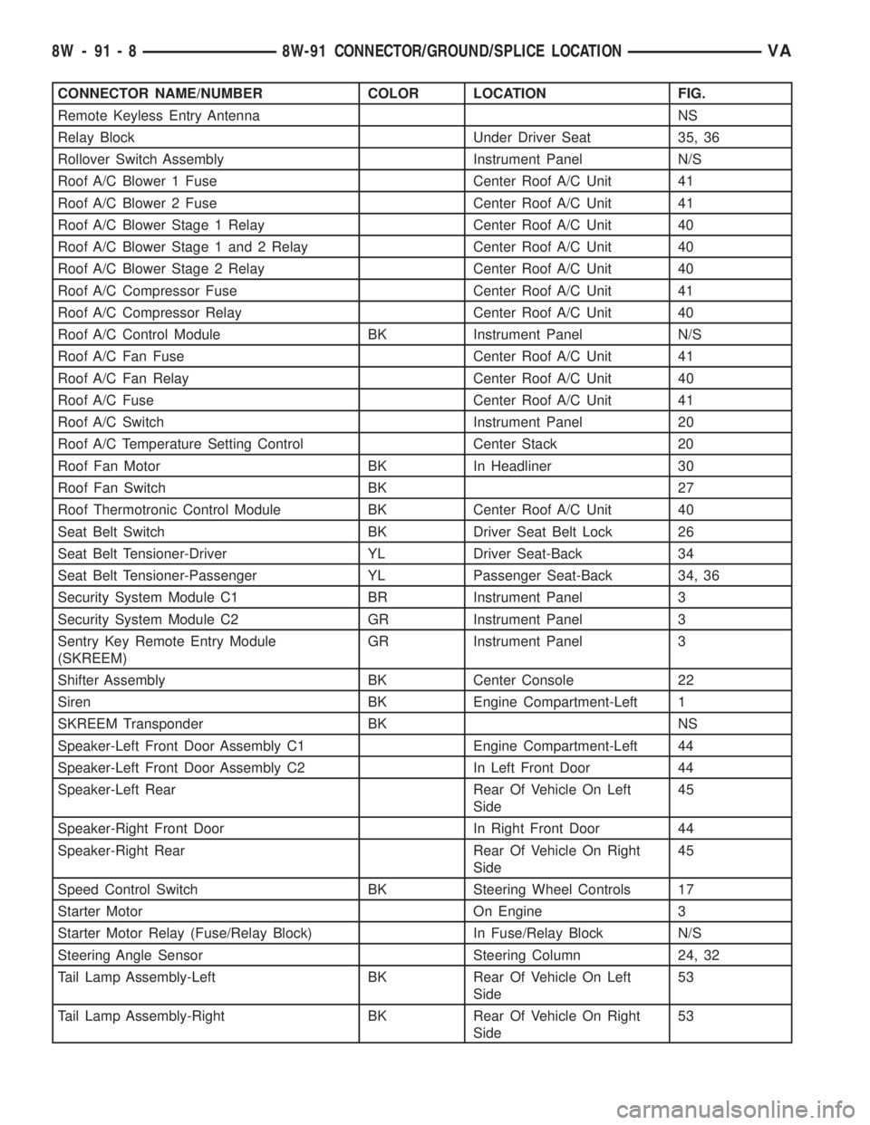
Remote Keyless Entry Antenna NS
Relay Block Under Driver Seat 35, 36
Rollover Switch Assembly Instrument Panel N/S
Roof A/C Blower 1 Fuse Center Roof A/C Unit 41
Roof A/C Blower 2 Fuse Center Roof A/C Unit 41
Roof A/C Blower Stage 1 Relay Center Roof A/C Unit 40
Roof A/C Blower Stage 1 and 2 Relay Center Roof A/C Unit 40
Roof A/C Blower Stage 2 Relay Center Roof A/C Unit 40
Roof A/C Compressor Fuse Center Roof A/C Unit 41
Roof A/C Compressor Relay Center Roof A/C Unit 40
Roof A/C Control Module BK Instrument Panel N/S
Roof A/C Fan Fuse Center Roof A/C Unit 41
Roof A/C Fan Relay Center Roof A/C Unit 40
Roof A/C Fuse Center Roof A/C Unit 41
Roof A/C Switch Instrument Panel 20
Roof A/C Temperature Setting Control Center Stack 20
Roof Fan Motor BK In Headliner 30
Roof Fan Switch BK 27
Roof Thermotronic Control Module BK Center Roof A/C Unit 40
Seat Belt Switch BK Driver Seat Belt Lock 26
Seat Belt Tensioner-Driver YL Driver Seat-Back 34
Seat Belt Tensioner-Passenger YL Passenger Seat-Back 34, 36
Security System Module C1 BR Instrument Panel 3
Security System Module C2 GR Instrument Panel 3
Sentry Key Remote Entry Module
(SKREEM)GR Instrument Panel 3
Shifter Assembly BK Center Console 22
Siren BK Engine Compartment-Left 1
SKREEM Transponder BK NS
Speaker-Left Front Door Assembly C1 Engine Compartment-Left 44
Speaker-Left Front Door Assembly C2 In Left Front Door 44
Speaker-Left Rear Rear Of Vehicle On Left
Side45
Speaker-Right Front Door In Right Front Door 44
Speaker-Right Rear Rear Of Vehicle On Right
Side45
Speed Control Switch BK Steering Wheel Controls 17
Starter Motor On Engine 3
Starter Motor Relay (Fuse/Relay Block) In Fuse/Relay Block N/S
Steering Angle Sensor Steering Column 24, 32
Tail Lamp Assembly-Left BK Rear Of Vehicle On Left
Side53
Tail Lamp Assembly-Right BK Rear Of Vehicle On Right
Side53
8W - 91 - 8 8W-91 CONNECTOR/GROUND/SPLICE LOCATIONVA
Page 2159 of 2305
INSIDE HANDLE ACTUATOR......23-33, 23-36
INSTRUMENT CLUSTER................8J-2
INSTRUMENT PANEL ANTENNA CABLE....8A-2
INSTRUMENT PANEL ASSEMBLY........23-59
INSTRUMENT PANEL CENTER BEZEL.....23-57
INSTRUMENT PANEL DUCTS...........24-51
INTAKE AIR PRESSURE SENSOR........14-43
INTAKE AIR TEMPERATURE SENSOR.....14-42
INTAKE MANIFOLD....................9-65
INTERIOR..........................23-70
INTERMEDIATE SHAFT.................19-4
INTERNATIONAL SYMBOLS...............0-9
INTERNATIONAL SYMBOLS...........Intro.-2
INTRUSION SENSOR...................8Q-1
IN - CAR TEMPERATURE SENSOR.......24-21
JUMP STARTING.......................0-6
KEY / LOCK CYLINDER.................19-5
KNUCKLE.............................2-5
LAMPS / LIGHTING - EXTERIOR..........8L-2
LAMPS / LIGHTING - INTERIOR.........8L-28
LATCH RELEASE CABLE...............23-52
LATCH RELEASE HANDLE..............23-52
LATCH STRIKER.....................23-18
LATCH ..................23-18, 23-33, 23-52
LATCH / LOCK CONTROL...............23-38
LATERAL ACCELERATION SENSOR........5-33
LEFT MOUNT.........................9-55
LEVER..............................5-26
LICENSE PLATE BRACKET..............23-48
LICENSE PLATE LAMP BULB...........8L-19
LICENSE PLATE LAMP UNIT............8L-19
LINKAGE............................19-9
LIQUID LINE........................24-77
LOCK CYLINDER.....................23-18
LOW BEAM HEADLAMP BULB..........8L-20
LOW FUEL INDICATOR................8J-19
LOW OIL LEVEL INDICATOR............8J-20
LOWER BALL JOINT....................2-6
LOWER CONTROL ARM.................2-6
LOWER ROLLER ARM.................23-37
MAINTENANCE INDICATOR.............8J-20
MAINTENANCE SCHEDULES..............0-8
MALFUNCTION INDICATOR LAMP (MIL) . . . 8J-21
MANIFOLD AIR FLOW (MAF) SENSOR....14-44
MASTER CYLINDER...................5-17
MASTER LOCK SWITCH................8N-1
METRIC SYSTEM...................Intro.-6
MODE DOOR CABLES.................24-21
MULTI - FUNCTION INDICATOR..........8J-22
MULTI - FUNCTION SWITCH............8L-21
O2 SENSOR.........................14-45
ODOMETER.........................8J-22
OIL COOLER & LINES..................9-56
OIL FILTER ..........................9-57
OIL JET .............................9-57
OIL PAN .............................9-58
OIL PUMP...........................9-61
OIL PUMP.........................21-154
OIL SENSOR.........................9-64
OIL ................................9-56
OPENING DIMENSIONS................23-93
OUTPUT SHAFT BEARING.............21-156
OUTPUT SHAFT SEAL................21-159
PAINT TOUCH - UP...................23-77
PAINT.............................23-77
PARK BRAKE INDICATOR..............8J-23
PARK BRAKE SWITCH.................8L-21
PARK LOCK CABLE..................21-160
PARKING BRAKE......................5-23
PASSENGER AIRBAG BRACKET.........8O-27
PASSENGER AIRBAG.................8O-24
PASSENGER HEATED SEAT SWITCH.....8G-13
PEDAL..............................5-19
PISTON & CONNECTING ROD............9-45
PISTON RINGS.......................9-52
PISTONS..........................21-163
PLANETARY GEARTRAIN..............21-164
PLUMBING.........................24-61
POWER BRAKE BOOSTER...............5-19
POWER DISTRIBUTION CENTER.......8W-97-3
POWER DISTRIBUTION..............8W-97-1
POWER MIRROR SWITCH..............8N-3
POWER MIRRORS....................8N-3
POWER OUTLET
...................8W-97-3
POWER WINDOW SWITCH
..............8N-5
POWER WINDOWS
....................8N-5
PROP ROD
.........................23-53
PROPELLER SHAFT
.................3-1, 3-7PUMP.............................19-11
QUARTER TRIM PANEL................23-74
QUARTER WINDOW..................23-84
RADIATOR CROSSMEMBER............23-49
RADIATOR FAN.......................7-14
RADIATOR PRESSURE CAP..............7-19
RADIATOR...........................7-17
RADIO..............................8A-2
RAIN SENSOR CONTROL MODULE......8R-15
RAIN SENSOR.......................8R-12
REAR AXLE..........................3-12
REAR A / C CONDENSER FAN...........24-83
REAR A / C EVAPORATOR..............24-84
REAR A / C EXPANSION VALVE..........24-85
REAR BUMPER - STEP.................13-2
REAR CROSSMEMBER - TRANSMISSION . . 13-11
REAR DISCHARGE LINE...............24-88
REAR FASCIA........................13-3
REAR LATCH STRIKER................23-40
REAR LATCH........................23-40
REAR LIQUID LINE...................24-91
REAR RECEIVER / DRIER..............24-94
REAR REFRIGERANT RESERVOIR........24-95
REAR SEAT BACK SHIELD..............23-82
REAR SEAT BELT & RETRACTOR........8O-28
REAR SEAT BELT BUCKLE.............8O-30
REAR SIDE MARKER LAMP BULB.......8L-22
REAR SUCTION LINE..................24-96
REAR TURN LAMP BULB..............8L-23
REAR VIEW MIRROR.................23-75
REAR WHEEL SPEED SENSOR...........5-31
REAR WINDOW DEFOGGER GRID........8G-7
REAR WINDOW DEFOGGER RELAY.......8G-3
REAR WINDOW DEFOGGER SWITCH......8G-4
REAR...............................2-11
RECEIVER / DRIER...................24-79
RECIRCULATION DOOR ACTUATOR......24-22
REFRIGERANT LINE COUPLER..........24-98
REFRIGERANT OIL...................24-81
REFRIGERANT.......................24-80
RELAY...........................8W-97-4
REMOTE KEYLESS ENTRY
TRANSMITTER.......................8N-1
REPEATER LAMP BULB................8L-23
REPEATER LAMP UNIT................8L-24
RESTRAINTS.........................8O-2
RIGHT MOUNT.......................9-56
ROTORS............................5-20
SAFETY LATCH......................23-53
SEAL - PINION........................3-39
SEAT ADJUSTERS - FRONT.............23-81
SEAT BACK CUSHION / COVER - REAR....23-82
SEAT BACK - FRONT..................23-80
SEAT BELT SWITCH..................8O-31
SEAT BELT TENSIONER................8O-32
SEAT BELT TURNING LOOP ADJUSTER . . . 8O-33
SEAT CUSHION - FRONT...............23-80
SEAT CUSHION / COVER - REAR.........23-83
SEATBELT INDICATOR.................8J-24
SEAT - FRONT.......................23-79
SEAT - REAR........................23-81
SECURITY SYSTEM MODULE............8Q-2
SENTRY KEY REMOTE ENTRY MODULE....8Q-2
SERVO..............................8P-2
SHAFT - AXLE DUAL REAR WHEELS......3-27
SHAFT - AXLE SINGLE REAR WHEEL......3-23
SHIFT MECHANISM..................21-168
SHOCK..............................2-13
SHOES..............................5-27
SIDE CURTAIN AIRBAG................8O-35
SIDE IMPACT SENSOR................8O-39
SIDE VIEW MIRROR..................23-49
SIDE VIEW MIRROR - GLASS...........23-50
SIREN..............................8Q-4
SLIDING DOOR......................23-40
SOLENOID.........................21-171
SPARE TIRE CARRIER.................22-12
SPEAKER............................8A-2
SPEED CONTROL.....................8P-1
SPEEDOMETER......................8J-25
SPRING CLAMP PLATES.................2-8
SPRING SHACKLE.....................2-15
SPRING STOP PLATES..................2-9
SPRING
.........................2-7, 2-14
STABILIZER BAR
..................2-9, 2-15
STABILIZER LINK
.................2-10, 2-16
STABILIZER
.........................23-45
STARTER MOTOR RELAY
..............8F-35STARTER MOTOR....................8F-33
STARTING SYSTEM...................8F-28
STEERING ANGLE SENSOR..............5-32
STEERING COLUMN OPENING COVER....23-68
STEERING WHEEL.....................19-6
STEERING...........................19-1
STEPWELL SCUFF PADS...............23-75
STRUT..............................2-10
SUCTION LINE.......................24-81
SUN VISOR.........................23-76
SUPPORT PLATE......................5-23
SUPPRESSOR FILTER - REAR BLOWER
MOTOR............................24-41
SUPPRESSOR FILTER - REAR
CONDENSER FAN....................24-43
SWITCH.............................8P-3
TACHOMETER.......................8J-25
TAIL LAMP UNIT.....................8L-25
TAILPIPE............................11-3
TEMPERATURE CONTROL..............24-38
TEMPERATURE SENSOR...............24-40
TEMPERATURE SENSOR / PARK -
NEUTRAL CONTACT..................21-176
TERMINAL........................Intro.-10
THREADED HOLE REPAIR.............Intro.-6
TIE ROD END ........................19-10
TIME DELAY RELAY....................8L-35
TIMING CHAIN AND SPROCKETS.........9-72
TIMING CHAIN COVER.................9-70
TIMING CHAIN TENSIONER..............9-81
TIRES..............................22-7
TIRES / WHEELS......................22-1
TONE WHEEL........................5-32
TOP COVER.........................23-67
TOP COVER - CLUSTER................23-64
TOP COVER - TRAY...................23-65
TORQUE CONVERTER HUB SEAL.......21-184
TORQUE CONVERTER................21-178
TORQUE REFERENCES...............Intro.-9
TOWING.............................0-7
TRACTION CONTROL INDICATOR........8J-26
TRACTION CONTROL MALFUNCTION
INDICATOR.........................8J-27
TRAILER HITCH......................13-11
TRANSMISSION CONTROL MODULE......8E-6
TRANSPONDER KEY...................8Q-5
TRIM PANEL.............23-18, 23-34, 23-46
TURBOCHARGER SYSTEM..............11-3
TURBOCHARGER......................11-6
TURN SIGNAL INDICATOR..............8J-27
TURN SIGNAL RELAY.................8L-26
UNDERBODY LINES..................24-100
UPPER ROLLER ARM.................23-36
VACUUM PUMP.......................9-54
VALVE COOLER.......................25-6
VALVE SPRINGS......................9-35
VALVE STEM SEALS...................9-34
VALVE ..............................25-5
VEHICLE IDENTIFICATION NUMBER.....Intro.-1
VEHICLE THEFT SECURITY..............8Q-1
VIBRATION DAMPER...................9-53
VOLTAGE REGULATOR.................8F-24
WAIT - TO - START INDICATOR..........8J-28
WASHER FLUID INDICATOR............8J-29
WASHER FLUID LEVEL SWITCH.........8R-16
WASHER HOSES / TUBES..............8R-18
WASHER NOZZLE....................8R-18
WASHER PUMP / MOTOR..............8R-19
WASHER RESERVOIR.................8R-21
WATER IN FUEL SENSOR..............14-30
WATER PUMP........................7-20
WATER VALVE .......................24-83
WATER - IN - FUEL INDICATOR..........8J-29
WHEEL ALIGNMENT...................2-17
WHEELS...........................22-13
WINDOW MOTOR.....................8N-5
WINDOW REGULATOR - MANUAL........23-21
WINDOW REGULATOR - POWER........23-20
WINDSHIELD........................23-85
WIPER ARM........................8R-23
WIPER BLADE.......................8R-26
WIPER LINKAGE.....................8R-28
WIPER MOTOR......................8R-31
WIPER RELAY.......................8R-34
WIPERS/WASHERS....................8R-2
WIRING DIAGRAM INFORMATION......Intro.-1
YAW RATE SENSOR...................5-35
2 INDEXVA
Description Group-Page Description Group-Page Description Group-Page