2006 MERCEDES-BENZ SPRINTER weight
[x] Cancel search: weightPage 323 of 2305

enable the HCU to perform the brake fluid manage-
ment control as the combination/proportioning
valves.
The Bosch 5.7 system uses the CAB/HCU/Pump
Motor to make an integral electronic/hydraulic unit
which shares data with other electronic modules on
the vehicle via the CAN C Bus network. To access
DTCs from the CAB, the DRBIIItuses the K-ABS
line located in the Data Link Connector (DLC).
3.3 BRAKE ASSIST SYSTEM (HBA)
The Brake Assist System (HBA) analyzes how
hard and fast the driver wants to brake. It monitors
the brake pressure via a pressure sensor. The
passenger car brake assist system uses a vacuum
booster solenoid. The Sprinter uses the hydraulic
control unit to develop the brake pressure.
3.4 TCS (ASR)
The primary function of the Traction Control System
is to reduce wheel slip and maintain traction at the
driven wheels when the road surfaces are slippery. The
Traction Control System reduces wheel slip by applying
the brake that has lost traction. The system is designed
to operate at speeds below 50 km/h (30 mph). The
engine's torque can be reduced by the ECM via the CAN
C Bus, if necessary. The TCS can be deactivated with
switch on the dash. The Traction Control System uses
the ABS to indicate spinning tires to enable the traction
control function. The TCS software is in the CAB.
The TCS (ASR) performs the following functions:
1. Engine power derate
2. Engine deceleration regulation. If the vehicle is
on a patch of ice, the simple action of releasing
the throttle is enough to cause the rear wheels to
slip. To avoid this, the throttle input is regulated
so power drops slowly instead of abruptly. The
engine power is reduced (decelerated) as neces-
sary.
3.5 ELECTRONIC BRAKE DISTRIBUTION
(EBD)
The system was enhanced and eliminates the
need for the ALB system (load sensing valve). All
ESP equipped models will not have ALB. The EBV
system self-adapts to operating conditions. It de-
tects the vehicle's payload when the vehicle starts
and pulls away. Based on the acceleration rate
when the vehicle first pulls away from a standstill,
the system is able to calculate the actual payload.
This is a rough estimate which is used initially.
Later on, the system gathers more precise informa-
tion by monitoring the brake pressure and wheel
speed and negative slip when the driver applies thebrakes. The system will then produce a more accu-
rate calculation of payload depending on brake
retardation. The adaptation is erased when the
ignition is switched off. A new adaptation will occur
on the next driving cycle. By default, the system
acts upon the vehicle as if in an unloaded condition
(safe mode).
Once a new driving cycle begins with the vehicle
in a fully loaded condition (without having gathered
more precise information) the system will detect
ABS actuation in the front wheels and will allow
enough pressure to be applied to the rear axle, to an
extent where the wheels are just about to lock up
(maximum braking possible).
The system calculates the braking force at the
front and rear axles. If the driver applies the brakes
gently and then realizes he needs to apply the
brakes further, the EBV allows the proper pressure
to be applied to the front and rear brakes.
The EBV also contains a feature called ªcorner
brake systemº (CBS) which operates when the ve-
hicle is braked while cornering to avoid a possible
oversteering condition. The EBV monitors the
wheel speed of both rear wheels to detect when the
vehicle is cornering and allows precise brake pres-
sure application to the front and rear brakes. Also
when the brakes are applied during cornering, the
outer wheels get more of the vehicle's weight while
the inner wheels get less weight and could lose
traction (wheel lock up). The EBV system splits the
pressure between left and right sides in addition to
front and rear brakes.
3.6 VEHICLE CONTROLLING (FZR)
Vehicle controlling (FZR)requires additional
sensors to operate. The term ESP refers to the
software of the system. The term FZR refers to the
system controller. The TCS (ASR) system requires
wheel speed sensors to monitor wheel slip and CAN
bus communications to regulate engine power. In
addition to these inputs, the vehicle controlling
(FZR) requires a steering angle sensor, and a lateral
acceleration/yaw rate sensor.
The ESP system does not take the vehicle load
into account. Instead, the coefficient of friction is
calculated in a 20 millisecond period, where the
controller measures the rate at which the wheel
speed is decelerated, as brake pressure is applied to
the wheel.
3.7 SYSTEM COMPONENTS
²Controller Antilock Brake (CAB)
²Hydraulic Control Unit (HCU)
²Pump Motor
2
GENERAL INFORMATION
Page 707 of 2305
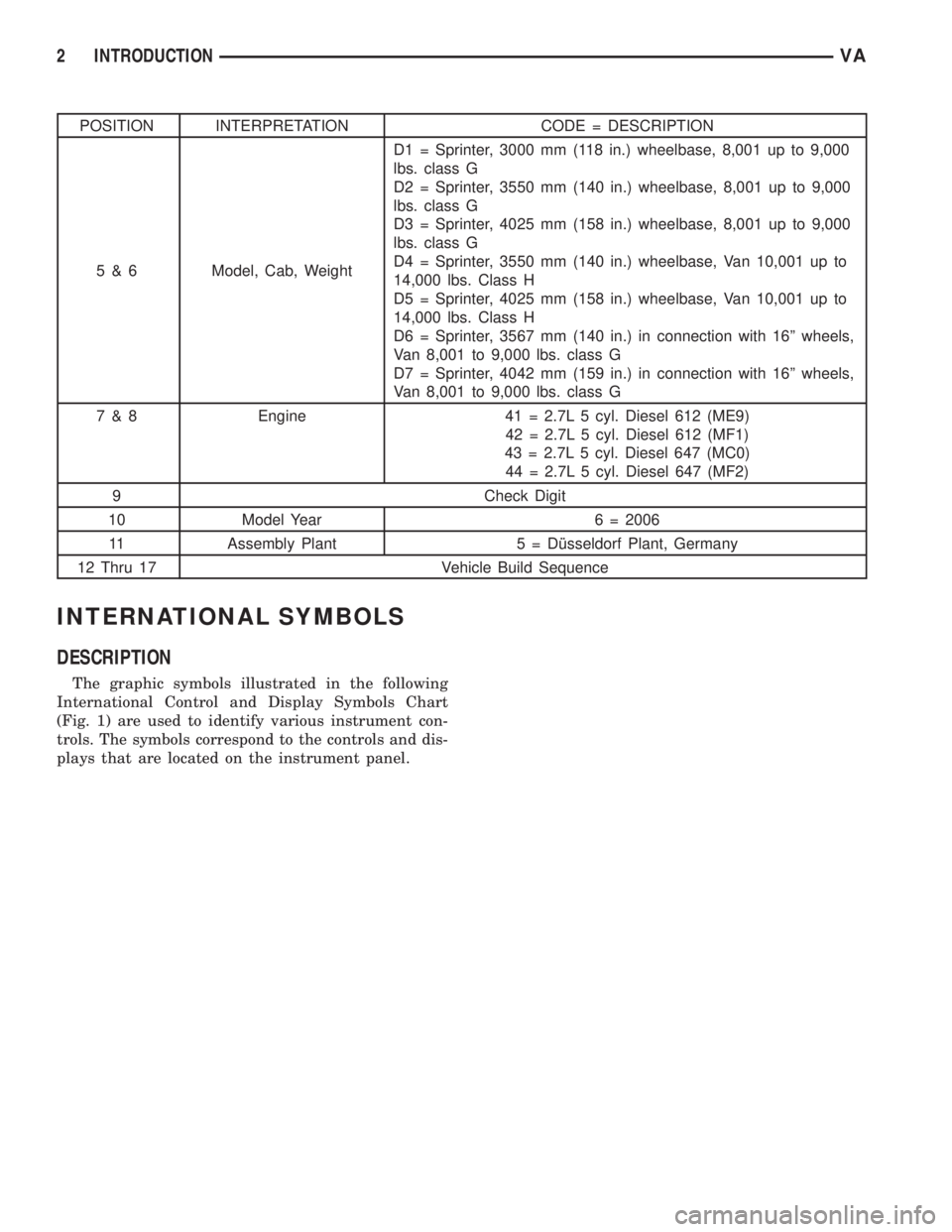
POSITION INTERPRETATION CODE = DESCRIPTION
5 & 6 Model, Cab, WeightD1 = Sprinter, 3000 mm (118 in.) wheelbase, 8,001 up to 9,000
lbs. class G
D2 = Sprinter, 3550 mm (140 in.) wheelbase, 8,001 up to 9,000
lbs. class G
D3 = Sprinter, 4025 mm (158 in.) wheelbase, 8,001 up to 9,000
lbs. class G
D4 = Sprinter, 3550 mm (140 in.) wheelbase, Van 10,001 up to
14,000 lbs. Class H
D5 = Sprinter, 4025 mm (158 in.) wheelbase, Van 10,001 up to
14,000 lbs. Class H
D6 = Sprinter, 3567 mm (140 in.) in connection with 16º wheels,
Van 8,001 to 9,000 lbs. class G
D7 = Sprinter, 4042 mm (159 in.) in connection with 16º wheels,
Van 8,001 to 9,000 lbs. class G
7 & 8 Engine 41 = 2.7L 5 cyl. Diesel 612 (ME9)
42 = 2.7L 5 cyl. Diesel 612 (MF1)
43 = 2.7L 5 cyl. Diesel 647 (MC0)
44 = 2.7L 5 cyl. Diesel 647 (MF2)
9 Check Digit
10 Model Year 6 = 2006
11 Assembly Plant 5 = Dîsseldorf Plant, Germany
12 Thru 17 Vehicle Build Sequence
INTERNATIONAL SYMBOLS
DESCRIPTION
The graphic symbols illustrated in the following
International Control and Display Symbols Chart
(Fig. 1) are used to identify various instrument con-
trols. The symbols correspond to the controls and dis-
plays that are located on the instrument panel.
2 INTRODUCTIONVA
Page 731 of 2305

INSTALLATION
(1) Install the steering knuckle on the lower ball
joint stud (Fig. 6).
(2) Install the lower ball joint nut (Fig. 6). Tighten
to 280 N´m (206 ft. lbs.)
(3) Install the strut to the steering knuckle (Fig.
6). Tighten to 185 N´m (136 ft. lbs.).
(4) Install the outer tie rod end to the steering
knuckle (Fig. 6) and tighten the nut to 130 N´m (96
ft. lbs.).
(5) Install the ABS sensor by pushing the sensor
all the way into the knuckle and the sensor will self
adjust when the wheel is turned.
(6) Install the hub/bearing (Refer to 2 - SUSPEN-
SION/FRONT/HUB / BEARING - INSTALLATION).
(7) Install the disc brake caliper adapter with the
brake caliper (Refer to 5 - BRAKES/HYDRAULIC/
MECHANICAL/DISC BRAKE CALIPER ADAPTER -
INSTALLATION).
(8) Install the front wheels (Refer to 22 - TIRES/
WHEELS/WHEELS - INSTALLATION).
(9) Lower the vehicle.
(10) Check and set toe if necessary (Refer to 2 -
SUSPENSION/WHEEL ALIGNMENT - STANDARD
PROCEDURE).
LOWER BALL JOINT
REMOVAL
(1) Raise and support the vehicle.
(2) Remove the front tire and wheel assembly.
(3) Remove the front strut (Refer to 2 - SUSPEN-
SION/FRONT/STRUT - REMOVAL).(4) Remove the steering knuckle (Refer to 2 - SUS-
PENSION/FRONT/KNUCKLE - REMOVAL).
(5) Remove the lower ball joint using special tool
9294-1 (Driver) with 9294-2 (Reciever) and C-4212±F.
(Fig. 7).
INSTALLATION
(1) Install the ball joint into the lower control arm
using special tool 9294-3 (Installer ring) inserted in
9294-2 (Reciever) and C-4212±F (Fig. 7).
(2) Install the front strut (Refer to 2 - SUSPEN-
SION/FRONT/STRUT - INSTALLATION).
(3) Install the steering knuckle (Refer to 2 - SUS-
PENSION/FRONT/KNUCKLE - INSTALLATION).
(4) Install the tire and wheel assembly (Refer to 22
- TIRES/WHEELS/WHEELS - INSTALLATION).
(5) Lower the vehicle.
(6) Check the front wheel alignment (Refer to 2 -
SUSPENSION/WHEEL ALIGNMENT - SPECIFICA-
TIONS).
LOWER CONTROL ARM
REMOVAL
(1) Insert spring blocks special tool 9288 between
the spring and the spring clamp plates, While the
vehicles wheels are on the ground.
(2) Raise and support the vehicle.
(3) Remove the front wheels (Refer to 22 - TIRES/
WHEELS/WHEELS - REMOVAL).
(4) Remove the disc brake caliper adapter (Refer to
5 - BRAKES/HYDRAULIC/MECHANICAL/DISC
BRAKE CALIPER ADAPTER - REMOVAL).Hang
the caliper. Do not allow brake hose to support
the caliper weight.
(5) Remove the retaining nut holding the tie rod to
the steering knuckle (Fig. 8).
Fig. 6 STEERING KNUCKLE
1 - STRUT
2 - STRUT BOLT
3 - STEERING KNUCKLE
4 - LOWER BALL JOINT NUT
5 - OUTER TIE ROD END RETAINING NUT
6 - INNER TIE ROD END
7 - LOWER CONTROL ARM
Fig. 7 LOWER BALL JOINT
1 - LOWER CONTROL ARM
2 - LOWER BALL JOINT
2 - 6 FRONTVA
Page 733 of 2305

(11) Separate the lower ball joint from the knuckle
using special tool 9282.
(12) Remove the lower control arm nuts and bolts
from the frame.
(13) Remove the lower control arm from the frame
(Fig. 9).
NOTE: To avoid damaging the transverse leaf
spring, cushion the pad on the jack accordingly.
(14) Support the transverse leaf spring in the cen-
ter with a jack.
(15) Remove the left and right spring clamp plates
(Refer to 2 - SUSPENSION/FRONT/SPRING CLAMP
PLATES - REMOVAL) (Fig. 9).
NOTE: The upper spring blocks between the engine
cradle and the spring are color coded, Make sure
not to mix the blocks per sides. The blocks are dif-
ferent in sizes to accommodate the weight of the
vehicle and driver in order for the vehicle to sit
level.
(16) Lower the jack and remove the transverse leaf
spring towards the side.INSTALLATION
NOTE: To avoid damaging the transverse leaf
spring, cushion the pad on the jack accordingly.
NOTE: Hand tighten all bolts until vehicle is on the
ground, unless the bushings may become distorted.
NOTE: The height blocks between the engine cradle
and the spring are color coded, Make sure not to
mix the blocks per sides. The blocks are different in
sizes to accommodate the weight of the vehicle and
driver in order for the vehicle to sit level.
(1) Install the transverse leaf spring in the center
with a jack with all the rubber mounts attached.
(2) Install the lower control arm to the frame (Fig.
9).
(3) Install the knuckle on the lower ball joint.
(4) Raise the lower control arm approximately 10
mm with a jack.
(5) Install both stop plate bolts to the lower control
arm
(6) Install the strut bolts to the steering knuckle.
(7) Reinstall the tie rod to the steering knuckle
(Fig. 9). Tighten to 150 N´m (110 ft. lbs.).
(8) Install the ABS sensor all the way into the
steering knuckle, the sensor will adjust automatically
when the vehicle is moved (Fig. 9).
(9) Install the disc brake caliper adapter (Fig. 9).
Tighten to 170 N´m (125 ft. lbs.).
(10) Install the front wheels.
(11) Lower the vehicle.
(12) Install the spring clamp plates (Fig. 9).
Tighten (M-10 bolts) to 65 N´m (48 ft. lbs.) (M-12
bolts) to 130 N´m (96 ft. lbs.).
(13) Roll the vehicle approximately 1 mm forwards
and the backwards, and rock firmly.
(14) Tighten the nuts on the lower control arm to
the frame to 150 N´m (110 ft. lbs.).
(15) Apply brake to actuate brake pressure.
SPRING CLAMP PLATES
REMOVAL
(1) Raise and support the vehicle.
(2) Install a jack under the lower ball joint and
lower the weight of the vehicle enough to allow a
wrench between the lower control arm and the
bracket tighten the nut.
(3) Remove the front and rear bolts to the spring
clamp plates.
(4) Remove the four inner retaining bolts and
nuts.
Fig. 9 FRONT SPRING
1 - NUT
2 - STRUT
3 - STOP PLATE
4 - STOP PLATE BOLT
5 - CALIPER ADAPTER BOLT
6 - DISC BRAKE CALIPER
7 - OUTER TIE ROD END NUT
8 - ABS SENSOR
9 - SPEED SENSOR
10 - LOWER CONTROL ARM RETAINING NUTS
11 - OUTER TIE ROD END
12 - RUBBER SPRING MOUNT
13 - SHEAR BUSHING
14 - SPRING CLAMP PLATE BOLT
15 - SPRING CLAMP PLATE
16 - LOWER RUBBER SPRING MOUNT
17 - SPRING
18 - STRUT BOLTS
19 - LOWER CONTROL ARM BOLTS
2 - 8 FRONTVA
Page 734 of 2305
(5) Remove the spring clamp plate and rubber
block.
(6) Remove the shear bushings from the front and
rear bolts.
INSTALLATION
(1) Install a jack under the lower ball joint and
lower the weight of the vehicle enough to allow a
wrench between the lower control arm and the
bracket tighten the nut.
(2) Fit one spring clamp plate together with the
lower spring rubber block.
(3) Install the bolt with the shear bushing on the
rear mounting,Do not tighten yet.
(4) Install the four retaining bolts for the spring
clamp plate. Tighten to 65 N´m (48 ft.lbs.).
(5) Align the holes for the front clamp plate joint
using a suitable drift (shear bushing not installed).
(6) Remove the alignment drift.
(7) Insert the shear bushing and retaining bolt
into the hole and tighten to 130 N´m (96 ft.lbs.).
(8) Remove the jack and lower the vehicle.
SPRING STOP PLATES
REMOVAL
(1) Raise and support the vehicle.
(2) Remove the tire and wheel assembly.
(3) Remove the lower end of the stabilizer link
from the stop plate.
(4) Remove the three bolts retaining the spring
stop plate from the lower control arm.
INSTALLATION
(1) Install the spring stop plate to the lower con-
trol arm. Tighten the bolts to 60 N´m (44 ft. lbs.).
(2) Install the stabilizer link to the spring stop
plate.
(3) Install the tire and wheel assembly.
(4) Lower the vehicle.
STABILIZER BAR
DESCRIPTION
The bar extends across the front underside of the
chassis and connects to the frame crossmember. The
ends of the bar mount to the lower suspension arm.
All mounting points of the stabilizer bar are isolated
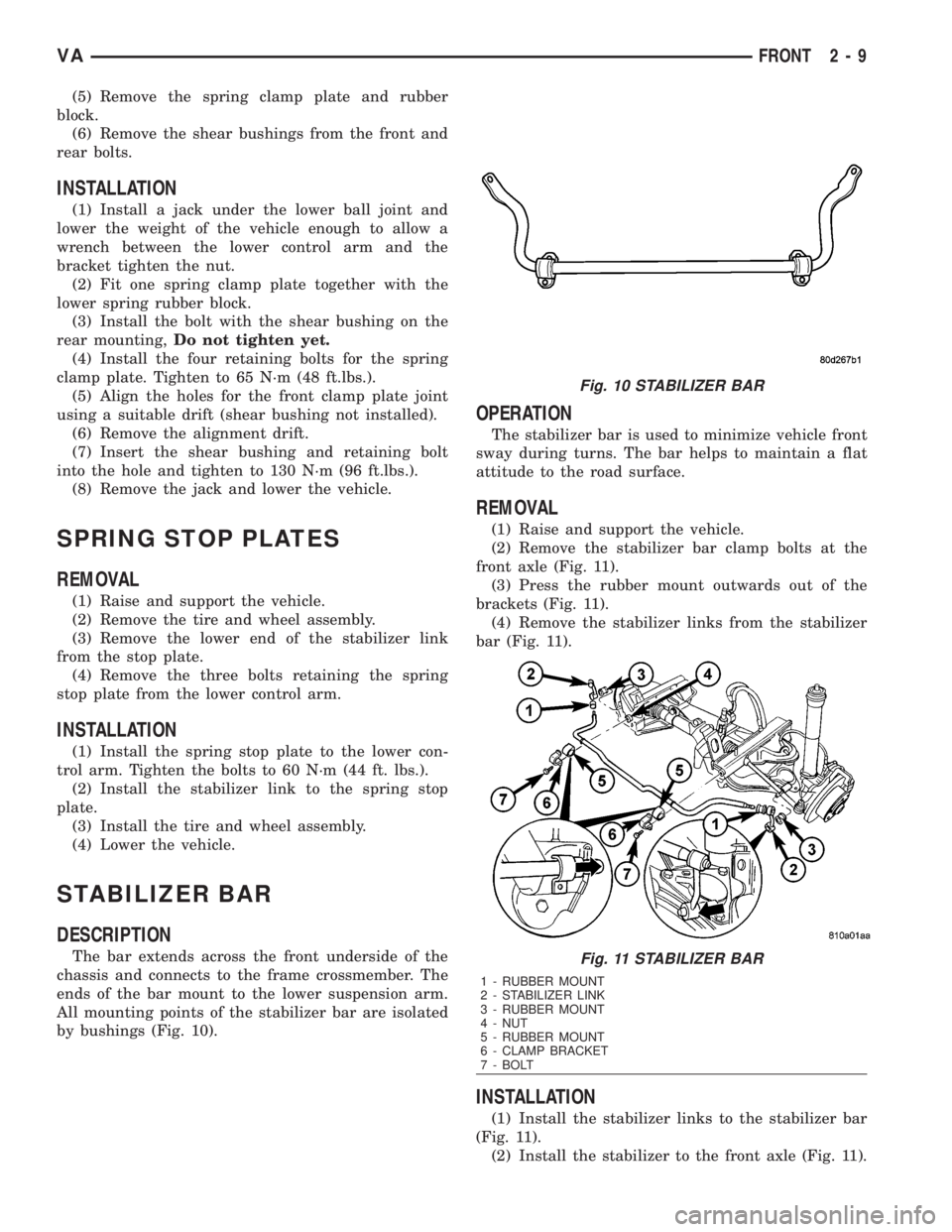
by bushings (Fig. 10).
OPERATION
The stabilizer bar is used to minimize vehicle front
sway during turns. The bar helps to maintain a flat
attitude to the road surface.
REMOVAL
(1) Raise and support the vehicle.
(2) Remove the stabilizer bar clamp bolts at the
front axle (Fig. 11).
(3) Press the rubber mount outwards out of the
brackets (Fig. 11).
(4) Remove the stabilizer links from the stabilizer
bar (Fig. 11).
INSTALLATION
(1) Install the stabilizer links to the stabilizer bar
(Fig. 11).
(2) Install the stabilizer to the front axle (Fig. 11).
Fig. 10 STABILIZER BAR
Fig. 11 STABILIZER BAR
1 - RUBBER MOUNT
2 - STABILIZER LINK
3 - RUBBER MOUNT
4 - NUT
5 - RUBBER MOUNT
6 - CLAMP BRACKET
7 - BOLT
VAFRONT 2 - 9
Page 736 of 2305
REAR
TABLE OF CONTENTS
page page
REAR
DESCRIPTION........................11
DIAGNOSIS AND TESTING - SPRING AND
SHOCK.............................11
SPECIFICATIONS - TORQUE CHART......12
SHOCK
DIAGNOSIS AND TESTING - SHOCK......13
REMOVAL...........................13
INSTALLATION.......................13
SPRING
DESCRIPTION........................14
OPERATION.........................14
REMOVAL
REMOVAL - (SRW)...................14REMOVAL - (DRW)...................14
INSTALLATION
INSTALLATION - (SRW)...............14
INSTALLATION - (DRW)...............15
SPRING SHACKLE
REMOVAL...........................15
INSTALLATION.......................15
STABILIZER BAR
REMOVAL...........................15
INSTALLATION.......................15
STABILIZER LINK
REMOVAL...........................16
INSTALLATION.......................16
REAR
DESCRIPTION
The rear suspension is comprised of:
²Shock Absorbers
²Jounce Bumpers
²Stabilizer Bar
²Leaf Springs
²Drive Axle
CAUTION: A vehicle should always be loaded so
the vehicle weight center-line is located immedi-
ately forward of the rear axle. Correct vehicle load-
ing provides proper front tire-to-road contact. This
results in maximum vehicle handling stability and
safety. Incorrect vehicle weight distribution can
cause excessive tire tread wear, spring fatigue or
failure, and erratic steering.
CAUTION: Suspension components with rubber/ure-
thane bushings (except stabilizer bar) should be
tightened with the vehicle at normal ride height. It is
important to have the springs supporting the weight
of the vehicle when the fasteners are torqued. If
springs are not at their normal ride position, vehicle
ride comfort could be affected and premature bush-
ing wear may occur.
DIAGNOSIS AND TESTING - SPRING AND
SHOCK
A knocking or rattling noise from a shock absorber
may be caused by movement between mountingbushings and metal brackets or attaching compo-
nents. These noises can usually be stopped by tight-
ening the attaching nuts. If the noise persists,
inspect for damaged and worn bushings, and attach-
ing components. Repair as necessary if any of these
conditions exist.
A squeaking noise from the shock absorber may be
caused by the hydraulic valving and may be intermit-
tent. This condition is not repairable and the shock
absorber must be replaced.
The shock absorbers are not refillable or adjust-
able. If a malfunction occurs, the shock absorber
must be replaced. To test a shock absorber, hold it in
an upright position and force the piston in and out of
the cylinder four or five times. The action throughout
each stroke should be smooth and even.
The spring eye and shock absorber bushings do not
require any type of lubrication. Do not attempt to
stop spring bushing noise by lubricating them.
Grease and mineral oil-base lubricants will deterio-
rate the bushing rubber.
If the vehicle is used for severe, off-road operation,
the springs should be examined periodically. Check
for broken and shifted leafs, loose and missing clips,
and broken center bolts. Refer to Spring and Shock
Absorber Diagnosis chart for additional information.
VAREAR 2 - 11
Page 742 of 2305
WHEEL ALIGNMENT
TABLE OF CONTENTS
page page
WHEEL ALIGNMENT
DESCRIPTION........................17
DIAGNOSIS AND TESTING - PRE-ALIGNMENT
INSPECTION.........................17STANDARD PROCEDURE - TOE
ADJUSTMENT........................18
SPECIFICATIONS.....................19
WHEEL ALIGNMENT
DESCRIPTION
NOTE: Camber and Caster are not adjustable on
this vehicle. (TOE ONLY).
NOTE: Suspension components with rubber/ure-
thane bushings should be tightened with the vehi-
cle at normal ride height. It is important to have the
springs supporting the weight of the vehicle when
the fasteners are torqued. If springs are not at their
normal ride position, vehicle ride comfort could be
affected and premature bushing wear may occur.
Wheel alignment involves the correct positioning of
the wheels in relation to the vehicle. The positioning
is accomplished through suspension and steering
linkage adjustments. An alignment is considered
essential for efficient steering, good directional stabil-
ity and to minimize tire wear. The most important
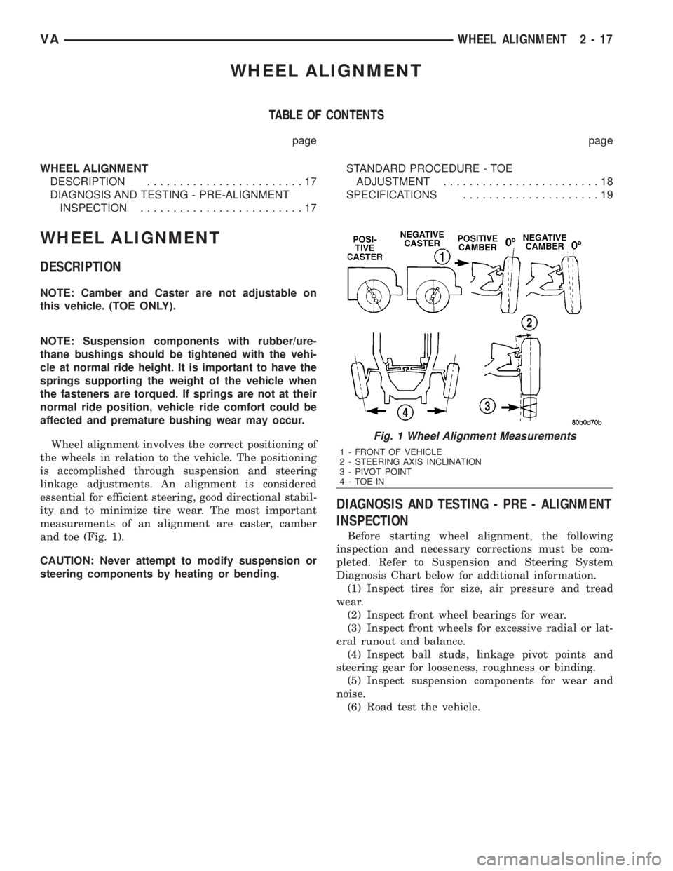
measurements of an alignment are caster, camber
and toe (Fig. 1).
CAUTION: Never attempt to modify suspension or
steering components by heating or bending.
DIAGNOSIS AND TESTING - PRE - ALIGNMENT
INSPECTION
Before starting wheel alignment, the following
inspection and necessary corrections must be com-
pleted. Refer to Suspension and Steering System
Diagnosis Chart below for additional information.
(1) Inspect tires for size, air pressure and tread
wear.
(2) Inspect front wheel bearings for wear.
(3) Inspect front wheels for excessive radial or lat-
eral runout and balance.
(4) Inspect ball studs, linkage pivot points and
steering gear for looseness, roughness or binding.
(5) Inspect suspension components for wear and
noise.
(6) Road test the vehicle.
Fig. 1 Wheel Alignment Measurements
1 - FRONT OF VEHICLE
2 - STEERING AXIS INCLINATION
3 - PIVOT POINT
4 - TOE-IN
VAWHEEL ALIGNMENT 2 - 17
Page 747 of 2305
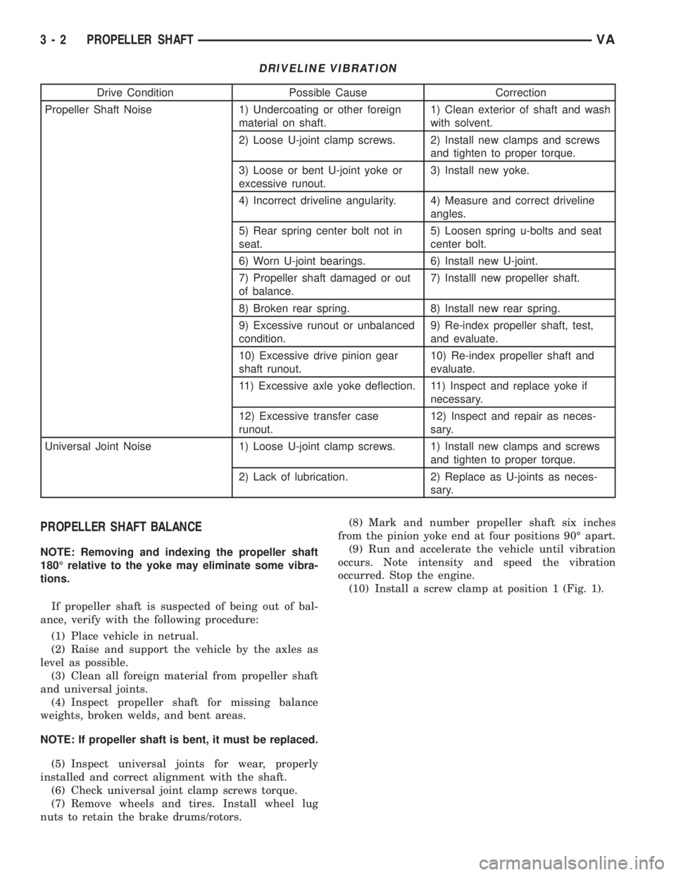
DRIVELINE VIBRATION
Drive Condition Possible Cause Correction
Propeller Shaft Noise 1) Undercoating or other foreign
material on shaft.1) Clean exterior of shaft and wash
with solvent.
2) Loose U-joint clamp screws. 2) Install new clamps and screws
and tighten to proper torque.
3) Loose or bent U-joint yoke or
excessive runout.3) Install new yoke.
4) Incorrect driveline angularity. 4) Measure and correct driveline
angles.
5) Rear spring center bolt not in
seat.5) Loosen spring u-bolts and seat
center bolt.
6) Worn U-joint bearings. 6) Install new U-joint.
7) Propeller shaft damaged or out
of balance.7) Installl new propeller shaft.
8) Broken rear spring. 8) Install new rear spring.
9) Excessive runout or unbalanced
condition.9) Re-index propeller shaft, test,
and evaluate.
10) Excessive drive pinion gear
shaft runout.10) Re-index propeller shaft and
evaluate.
11) Excessive axle yoke deflection. 11) Inspect and replace yoke if
necessary.
12) Excessive transfer case
runout.12) Inspect and repair as neces-
sary.
Universal Joint Noise 1) Loose U-joint clamp screws. 1) Install new clamps and screws
and tighten to proper torque.
2) Lack of lubrication. 2) Replace as U-joints as neces-
sary.
PROPELLER SHAFT BALANCE
NOTE: Removing and indexing the propeller shaft
180É relative to the yoke may eliminate some vibra-
tions.
If propeller shaft is suspected of being out of bal-
ance, verify with the following procedure:
(1) Place vehicle in netrual.
(2) Raise and support the vehicle by the axles as
level as possible.
(3) Clean all foreign material from propeller shaft
and universal joints.
(4) Inspect propeller shaft for missing balance
weights, broken welds, and bent areas.
NOTE: If propeller shaft is bent, it must be replaced.
(5) Inspect universal joints for wear, properly
installed and correct alignment with the shaft.
(6) Check universal joint clamp screws torque.
(7) Remove wheels and tires. Install wheel lug
nuts to retain the brake drums/rotors.(8) Mark and number propeller shaft six inches
from the pinion yoke end at four positions 90É apart.
(9) Run and accelerate the vehicle until vibration
occurs. Note intensity and speed the vibration
occurred. Stop the engine.
(10) Install a screw clamp at position 1 (Fig. 1).
3 - 2 PROPELLER SHAFTVA