2006 MERCEDES-BENZ SPRINTER recommended oil
[x] Cancel search: recommended oilPage 325 of 2305

read opposite switch states.Note: The BS and
BLS are in the same switch housing.
BRAKE LAMP SWITCH (BLS):This switch pre-
pares the CAB for a possible antilock event. The
CAB uses an output state voltage from the BLS
when the brake pedal is either depressed/released.
The Fused Ignition Switch Output circuit supplies
12 volts to the BLS. A depressed brake pedal will
close the BLS circuit and the BLS Output circuit
supplies 12 volts at the CAB. When the driver
releases the brake pedal, the BLS Output circuit
voltage drops to 0 volts and the CAB senses the
brake pedal state. This tells the CAB what position
the brake pedal is currently in to make an ABS
event possible. When using the DRBIIItin Inputs/
Outputs, the BS and BLS will read opposite switch
states.Note: The BS and BLS are in the same
switch housing.
TRACTION CONTROL SYSTEM SWITCH
(TCSS):This switch signals the CAB to either turn
ON or OFF the TCS. The driver can toggle the
TCSS, which receives 12 volts from the D (+) Relay
Output circuit. Depending on the position of the
TCSS, open or closed, the CAB receives the TCSS
state voltage on the TCS Switch Sense circuit.
When 12 volts are applied to the TCS Switch Sense
circuit, the TCS is OFF. When no voltage is present,
the TCS is ON.
WHEEL SPEED SENSORS AND TONE
WHEELS:The Bosch 5.7 system uses one passive
WSS on each wheel. The sensor measures the wheel
speed by monitoring a rotating tone wheel. As the
teeth of the tone wheel move through the magnetic
field of the sensor an AC voltage and amperage is
generated. This signal frequency increases or de-
creases proportionally to the speed of the wheel.
The CAB monitors this signal to check for a sudden
change in single or multiple wheel decelerations. If
the deceleration of one or more wheels is not within
a predetermined amount, the CAB takes control for
antilock action through the HCU. Each WSS has a
magnetic inductive pick up coil (WSS) that is
mounted to a fixed component. There is an air gap
between the tone wheel and the speed sensor as-
sembly. Diagnostically, the coils of the Wheel Speed
Sensors have the same amount of resistance. When
measured across the CAB harness connector termi-
nals, the resistance should be between 1100 - 1800
ohms. Refer to service manual for WSS replacement
and air gap specifications.
Correct ABS operation is dependent on Tone
Wheel speed signal from the WSS. The vehicle
wheels and tires should all be the same size and
type to get accurate signals. In addition, all tires
should be at recommended tire pressures.3.7.5 SELF TESTS
The system software includes several self tests
that are performed every time the ignition is turned
on and the vehicle is driven. Some of the self tests
occur immediately, while others occur under normal
driving conditions while not in antilock operation.
The CAB checks continuously for a missing or
erratic WSS signals/circuits, tone wheels, solenoids,
pump motor or solenoid relay by performing several
tests such as: dynamic, static, ohmic, voltage drop,
and timed response. If any component exhibits a
fault during testing, the CAB will request to illumi-
nate the ABS and TCS warning indicators.
As an additional check of the ESP system, a road
test procedure is available on the DRBIIIt. This
test should be carried out when any ESP component
is replaced in order to ensure proper function. Since
the wheel speed sensors are required inputs to the
ESP, this test should also be performed if the wheel
speed sensors are replaced.
First, the brakes are applied with the vehicle
stationary. Then, the vehicle is driven at approxi-
mately 6 MPH. The driver has to make left and
right turns, with a minimum 90 degree steering
turning angle. If the indicator lamp goes out, every-
thing is in order. If the lamp remains illuminated,
the DRBIIItwill display the fault codes that are
causing the test to fail. The road test function is set
in the ESP control module, and can only be deacti-
vated once there are no more fault codes detected.
The Steering Angle Sensor must be initialized. A
procedure is carried out using the DRBIIItto
ensure that the module detects the exact position of
the sensor. The sensor must be calibrated any time
wheel alignment is changed, the steering column is
removed and re-installed, or the sensor is replaced.
3.8 USING THE DRBIIIT
Refer to the DRBIIItuser 's guide for instructions
and assistance with reading diagnostic trouble
codes, erasing diagnostic trouble codes and other
DRBIIItfunctions.
3.9 DRBIIITERROR MESSAGES
Under normal operation, the DRBIIItwill dis-
play one of only two error messages:
Ð User-Requested WARM Boot or User-Requested
COLD Boot.
If the DRBIIItshould display any other error
message, record the entire display and call the
STAR Center for information and assistance. This
is a sample of such an error message display:
4
GENERAL INFORMATION
Page 717 of 2305
AXLE FLUID
Use oils approved to MB 235.0 or 235.6, such as
Shell Spirax MB90, Caltex Hypoid LD, or MOPARt
part number 4874469, or equivalent. An API GL-5/
MIL-2105-E SAE 90 Hypoid Gear Oil may be substi-
tuted. Reduced axle durability may result if an
unapproved product is used.
BRAKE FLUID
Use brake fluid approved to MB 331.0, such as
Intac B026D, MOPARtBrake & Clutch Fluid, part
number 04549625AC, or equivalent. If the approved
product is not available, use a DOT 4 brake fluid:
minimum dry boiling point (ERBP) 500ÉF, minimum
wet boiling point (WERBP) 356ÉF, maximum viscos-
ity 1500 mm
2/s, conforming to FMVSS 116 and ISO
4925.
HOAT COOLANT
WARNING: ANTIFREEZE IS AN ETHYLENE-GLYCOL
BASE COOLANT AND IS HARMFUL IF SWAL-
LOWED OR INHALED. IF SWALLOWED, DRINK
TWO GLASSES OF WATER AND INDUCE VOMIT-
ING. IF INHALED, MOVE TO FRESH AIR AREA.
SEEK MEDICAL ATTENTION IMMEDIATELY. DO NOT
STORE IN OPEN OR UNMARKED CONTAINERS.
WASH SKIN AND CLOTHING THOROUGHLY AFTER
COMING IN CONTACT WITH ETHYLENE-GLYCOL.
KEEP OUT OF REACH OF CHILDREN. DISPOSE OF
GLYCOL BASE COOLANT PROPERLY, CONTACT
YOUR DEALER OR GOVERNMENT AGENCY FOR
LOCATION OF COLLECTION CENTER IN YOUR
AREA. DO NOT OPEN A COOLING SYSTEM WHEN
THE ENGINE IS AT OPERATING TEMPERATURE OR
HOT UNDER PRESSURE, PERSONAL INJURY CAN
RESULT. AVOID RADIATOR COOLING FAN WHEN
ENGINE COMPARTMENT RELATED SERVICE IS
PERFORMED, PERSONAL INJURY CAN RESULT.
CAUTION: Use of Propylene-Glycol based coolants
is not recommended, as they provide less freeze
protection and less corrosion protection.
The cooling system is designed around the coolant.
The coolant must accept heat from engine metal, in
the cylinder head area near the exhaust valves and
engine block. Then coolant carries the heat to the
radiator where the tube/fin radiator can transfer the
heat to the air.
The use of aluminum cylinder blocks, cylinder
heads, and water pumps requires special corrosion
protection. Use coolant approved to MB 325.0, such
as EURO Peak Coolant/Anti-freeze (OLD WORLD
INDUSTRIES), Zerex G05 or G48 (The Valvoline
Company), Glysantin G05 (BASF AG), MOPARtpart
number 05066386AA, or an equivalent Extended LifeCoolant with the HOAT inhibitor system. This cool-
ant offers the best engine cooling without corrosion
when mixed with 50% anti-freeze and 50% distilled
water to obtain a freeze point of -37ÉC (-34ÉF). If it
loses color or becomes contaminated, drain, flush,
and replace with fresh properly mixed coolant solu-
tion.
CAUTION: This coolant may not be mixed with any
other type of antifreeze. Mixing of coolants other
than specified (non-HOAT), may result in engine
damage that may not be covered under the new
vehicle warranty, and decreased corrosion protec-
tion.
CAUTION: Do not use coolant additives that are
claimed to improve engine cooling.
COOLANT PERFORMANCE
The required ethylene-glycol (antifreeze) and water
mixture depends upon climate and vehicle operating
conditions. The coolant performance of various mix-
tures follows:
Pure Water-Water can absorb more heat than a
mixture of water and ethylene-glycol. This is for pur-
pose of heat transfer only. Water also freezes at a
higher temperature and allows corrosion.
100 percent Ethylene-Glycol-The corrosion
inhibiting additives in ethylene-glycol need the pres-
ence of water to dissolve. Without water, additives
form deposits in system. These act as insulation
causing temperature to rise. The increased tempera-
ture can result in engine detonation. In addition, 100
percent ethylene-glycol freezes at -22ÉC (-8ÉF).
50/50 Ethylene-Glycol and Water-Is the recom-
mended mixture, it provides protection against freez-
ing to -37ÉC (-34ÉF). The antifreeze concentration
must alwaysbe a minimum of 44 percent, year-
round in all climates. If percentage is lower, engine
parts may be eroded by cavitation. Maximum protec-
tion against freezing is provided with a 68 percent
antifreeze concentration, which prevents freezing
down to -67.7ÉC (-90ÉF). A higher percentage will
freeze at a warmer temperature. Also, a higher per-
centage of antifreeze can cause the engine to over-
heat because specific heat of antifreeze is lower than
that of water.
CAUTION: Richer antifreeze mixtures cannot be
measured with normal field equipment and can
cause problems associated with 100 percent ethyl-
ene-glycol.
0 - 2 LUBRICATION & MAINTENANCEVA
Page 723 of 2305
effect panels. If necessary, remove the wheels from
the lifted end of the vehicle and lower the vehicle
closer to the ground, to increase the ground clearance
at the opposite end of the vehicle. Install lug nuts on
wheel attaching studs to retain brake drums.
RAMP ANGLE
If a vehicle with flat-bed towing equipment is used,
the approach ramp angle should not exceed 15
degrees.
TOWING WHEN KEYS ARE NOT AVAILABLE
When the vehicle is locked and keys are not avail-
able, use a flat bed hauler. A Wheel-lift or Sling-type
device can be used provided all the wheels are lifted
off the ground using tow dollies.
MAINTENANCE SCHEDULES
DESCRIPTION
The use of special lubricant additives is not recom-
mended. The use of such additives may affect the
warranty rights. With regard to legal stipulations
concerning emissions control, please note that
engines have to be serviced and adjusted in accor-
dance with special instructions and using special
measuring equipment. Modifications to or interfer-
ence with the emissions control systems are not per-
missible.
MAINTENANCE - WITHOUT ASSYST MAINTE-
NANCE COMPUTER
Maintenance Intervals
²Oil service ±Normal Operationevery 10,000
miles or 16,000 km or 12 months.
²Maintenance service every 30,000 miles or
48,000 km.
Additional work must be carried out at yearly
intervals.
MAINTENANCE - WITH ASSYST MAINTENANCE
COMPUTER
ASSYST provides information on the best possible
timing for maintenance work.
When the next maintenance service is due, this
will be indicated in the multi-function display with
the wrench icon symbol displayed in km/miles or
days.
²One wrench icon showing indicates Oil Service
is necessary.
²Two wrench icons showing indicates Mainte-
nance Service is necessary ± displayed in km/miles or
days.
If the display shows the number of days, a clock
symbol will also appear in the multi-function display.You should have the maintenance performed
within the stated period/distance.
The service indicator will be reset after an oil ser-
vice and/or maintenance service has been performed.
REGULAR CHECK - UPS
To maintain the safe operation of the vehicle, it is
recommended that the following tasks be performed
on a regular basis (i.e. weekly or whenever the vehi-
cle is refueled). Check:
²Engine oil level
²Brake system - fluid level
²Battery - acid level
²Windshield washer system and headlamp clean-
ing system - fluid level
²Mechanical assemblies (e.g. engine, transmis-
sion, etc.) - check for leaks
²Condition of tires and tires pressures
²All exterior lights
SPECIAL MAINTENANCE REQUIREMENTS
If bodies built by manufacturers other than
DaimlerChrysler Corporation are fitted to the vehi-
cle, the maintenance requirements and lubrication
intervals specified by the body manufacturer must be
adhered to, in addition to all standard maintenance
requirements.
Coolant
Corrosion inhibitor/antifreeze concentration in the
coolant should be checked before the onset of winter
(once year in countries with high prevailing temper-
atures).
Replace the coolant every five years or 100,000
miles.
Dust Filter for Heating / Ventilation Replacement
The dust filter and the tailgate interior filter are to
be renewed during routine maintenance service. If
operating conditions are dusty, these filters should be
renewed more frequently.
ENGINE OIL CHANGE AND FILTER REPLACEMENT
At a minimum, change the engine oil and oil filter
once a year ± even if the vehicle mileage per year is
extremely low. For standard oil service schedules
refer to the chapter oil service and maintenance ser-
vice.
Once a Year
Select the viscosity of the engine oil (SAE classes)
according to the outside air temperature.
Only use engine oil approved by DaimlerChrysler
Corporation if following the ASSYST system guide-
lines.
0 - 8 LUBRICATION & MAINTENANCEVA
Page 804 of 2305
FLUID
DIAGNOSIS AND TESTING - BRAKE FLUID
CONTAMINATION
Indications of fluid contamination are swollen or
deteriorated rubber parts.
Swollen rubber parts indicate the presence of
petroleum in the brake fluid.
To test for contamination, put a small amount of
drained brake fluid in clear glass jar. If fluid sepa-
rates into layers, there is mineral oil or other fluid
contamination of the brake fluid.
If brake fluid is contaminated, drain and thor-
oughly flush system. Replace master cylinder, ALB
Controller, caliper seals, Antilock Brakes hydraulic
unit and all hydraulic fluid hoses.
STANDARD PROCEDURE - BRAKE FLUID
LEVEL
Always clean the master cylinder reservoir and
caps before checking fluid level. If not cleaned, dirt
could enter the fluid.
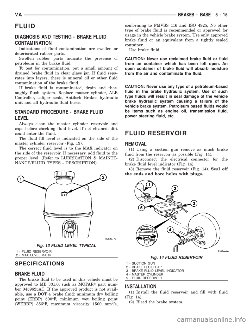
The fluid fill level is indicated on the side of the
master cylinder reservoir (Fig. 13).
The correct fluid level is to the MAX indicator on
the side of the reservoir. If necessary, add fluid to the
proper level. (Refer to LUBRICATION & MAINTE-
NANCE/FLUID TYPES - DESCRIPTION).
SPECIFICATIONS
BRAKE FLUID
The brake fluid to be used in this vehicle must be
approved to MB 331.0, such as MOPARtpart num-
ber 0459625AC. If the approved product is not avail-
able, use a DOT 4 brake fluid: minimum dry boiling
point (ERBP) 500ÉF, minimum wet boiling point
(WERBP) 356ÉF, maximum viscosity 1500 mm
2/s,conforming to FMVSS 116 and ISO 4925. No other
type of brake fluid is recommended or approved for
usage in the vehicle brake system. Use only approved
brake fluid or an equivalent from a tightly sealed
container.
Use brake fluid
CAUTION: Never use reclaimed brake fluid or fluid
from an container which has been left open. An
open container of brake fluid will absorb moisture
from the air and contaminate the fluid.
CAUTION: Never use any type of a petroleum-based
fluid in the brake hydraulic system. Use of such
type fluids will result in seal damage of the vehicle
brake hydraulic system causing a failure of the
vehicle brake system. Petroleum based fluids would
be items such as engine oil, transmission fluid,
power steering fluid, etc.
FLUID RESERVOIR
REMOVAL
(1) Using a suction gun remove as much brake
fluid from the reservoir as possible (Fig. 14).
(2) Disconnect the electrical connector for the
brake fluid level indicator (Fig. 14).
(3) Remove the fluid reservoir (Fig. 14).Seal off
the ends and bore holes with plugs.
INSTALLATION
(1) Install the fluid reservoir and fill with fluid
(Fig. 14).
(2) Bleed the brake system.
Fig. 13 FLUID LEVEL TYPICAL
1 - FLUID RESERVOIR
2 - MAX LEVEL MARK
Fig. 14 FLUID RESERVOIR
1 - SUCTION GUN
2 - BRAKE FLUID CAP
3 - BRAKE FLUID LEVEL INDICATOR
4 - MASTER CYLINDER
5 - FLUID RESERVOIR
VABRAKES - BASE 5 - 15
Page 836 of 2305

ENGINE
TABLE OF CONTENTS
page page
COOLANT
DESCRIPTION..........................9
DIAGNOSIS AND TESTING
COOLING SYSTEM LEAKS..............10
STANDARD PROCEDURE
ADDING ADDITIONAL COOLANT.........12
DRAINING COOLING SYSTEM...........12
REFILLING COOLING SYSTEM...........13
COOLANT LEVEL SENSOR
REMOVAL.............................13
INSTALLATION.........................14
RADIATOR FAN
REMOVAL.............................14
INSTALLATION.........................14
ENGINE BLOCK HEATER
REMOVAL.............................14
INSTALLATION.........................15
ENGINE COOLANT TEMP SENSOR
DESCRIPTION.........................15REMOVAL.............................15
INSTALLATION.........................15
ENGINE COOLANT THERMOSTAT
REMOVAL.............................16
INSTALLATION.........................16
FAN DRIVE VISCOUS CLUTCH
REMOVAL.............................17
INSTALLATION.........................17
RADIATOR
REMOVAL.............................17
INSTALLATION.........................19
RADIATOR PRESSURE CAP
DESCRIPTION.........................19
OPERATION...........................20
DIAGNOSIS AND TESTING - RADIATOR
PRESSURE CAP......................20
WATER PUMP
REMOVAL.............................20
INSTALLATION.........................22
COOLANT
DESCRIPTION
Coolant flows through the engine water jackets
and cylinder heads absorbing heat produced by the
engine during operation. The coolant carries heat to
the radiator and heater core. Here it is transferred to
ambient air passing through the radiator and heater
core fins.
The required ethylene-glycol (antifreeze) and water
mixture depends upon the climate and vehicle oper-
ating conditions. The recommended mixture of 50/50
ethylene-glycol and water will provide protection
against freezing to -37É C (-35É F). The antifreeze
concentrationmust alwaysbe a minimum of 44 per-
cent, year-round in all climates.If percentage is
lower than 44 percent, engine parts may be
eroded by cavitation, and cooling system com-
ponents may be severely damaged by corrosion.
Maximum protection against freezing is provided
with a 68 percent antifreeze concentration, which
prevents freezing down to -67.7É C (-90É F). A higher
percentage will freeze at a warmer temperature.
Also, a higher percentage of antifreeze can cause the
engine to overheat because the specific heat of anti-
freeze is lower than that of water.100 Percent Ethylene - Glycol - Should Not Be Used in
Chrysler Vehicles
Use of 100 percent ethylene-glycol will cause for-
mation of additive deposits in the system, as the cor-
rosion inhibitive additives in ethylene-glycol require
the presence of water to dissolve. The deposits act as
insulation, causing temperatures to rise to as high as
149É C (300É F). This temperature is hot enough to
melt plastic and soften solder. The increased temper-
ature can result in engine detonation. In addition,
100 percent ethylene-glycol freezes at -22É C (-8É F ).
Propylene - glycol Formulations - Should Not Be Used in
Chrysler Vehicles
Propylene-glycol formulations do not meet
Chrysler coolant specifications.It's overall effec-
tive temperature range is smaller than that of ethyl-
ene-glycol. The freeze point of 50/50 propylene-glycol
and water is -32É C (-26É F). 5É C higher than ethyl-
ene-glycol's freeze point. The boiling point (protection
against summer boil-over) of propylene-glycol is 125É
C (257ÉF)at96.5 kPa (14 psi), compared to 128É C
(263É F) for ethylene-glycol. Use of propylene-glycol
can result in boil-over or freeze-up in Chrysler vehi-
cles, which are designed for ethylene-glycol. Propy-
lene glycol also has poorer heat transfer
characteristics than ethylene glycol. This can
increase cylinder head temperatures under certain
conditions.
VAENGINE 7 - 9
Page 1628 of 2305
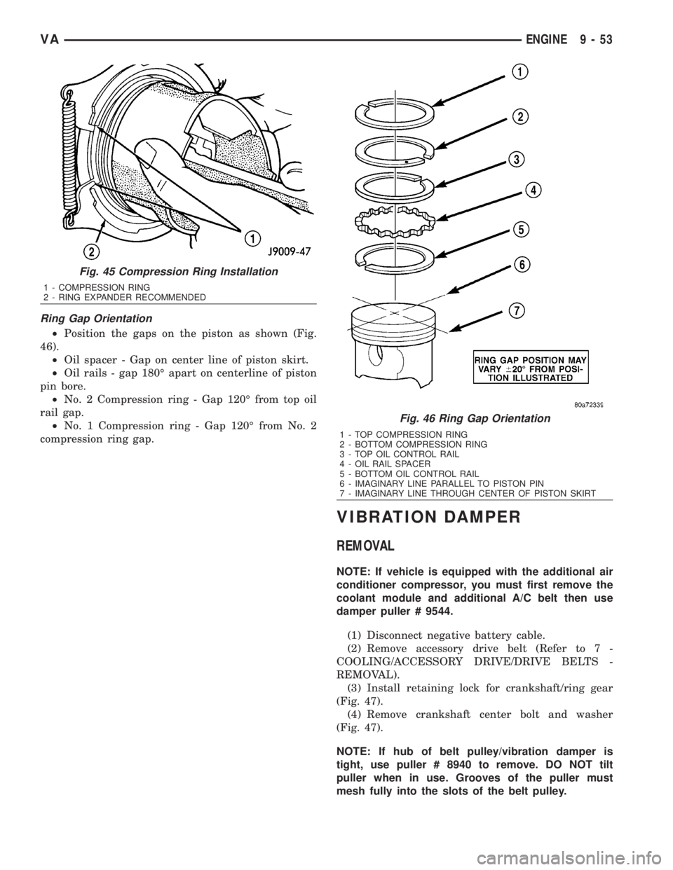
Ring Gap Orientation
²Position the gaps on the piston as shown (Fig.
46).
²Oil spacer - Gap on center line of piston skirt.
²Oil rails - gap 180É apart on centerline of piston
pin bore.
²No. 2 Compression ring - Gap 120É from top oil
rail gap.
²No. 1 Compression ring - Gap 120É from No. 2
compression ring gap.
VIBRATION DAMPER
REMOVAL
NOTE: If vehicle is equipped with the additional air
conditioner compressor, you must first remove the
coolant module and additional A/C belt then use
damper puller # 9544.
(1) Disconnect negative battery cable.
(2) Remove accessory drive belt (Refer to 7 -
COOLING/ACCESSORY DRIVE/DRIVE BELTS -
REMOVAL).
(3) Install retaining lock for crankshaft/ring gear
(Fig. 47).
(4) Remove crankshaft center bolt and washer
(Fig. 47).
NOTE: If hub of belt pulley/vibration damper is
tight, use puller # 8940 to remove. DO NOT tilt
puller when in use. Grooves of the puller must
mesh fully into the slots of the belt pulley.
Fig. 45 Compression Ring Installation
1 - COMPRESSION RING
2 - RING EXPANDER RECOMMENDED
Fig. 46 Ring Gap Orientation
1 - TOP COMPRESSION RING
2 - BOTTOM COMPRESSION RING
3 - TOP OIL CONTROL RAIL
4 - OIL RAIL SPACER
5 - BOTTOM OIL CONTROL RAIL
6 - IMAGINARY LINE PARALLEL TO PISTON PIN
7 - IMAGINARY LINE THROUGH CENTER OF PISTON SKIRT
VAENGINE 9 - 53
Page 1875 of 2305
CAUSES OF BURNT FLUID
Burnt, discolored fluid is a result of overheating
which has three primary causes.
1. Internal clutch slippage, usually caused by low
line pressure, inadequate clutch apply pressure, or
clutch seal failure.
2. A result of restricted fluid flow through the
main and/or auxiliary cooler. This condition is usu-
ally the result of a faulty or improperly installed
drainback valve, a damaged oil cooler, or severe
restrictions in the coolers and lines caused by debris
or kinked lines.
3. Heavy duty operation with a vehicle not prop-
erly equipped for this type of operation. Trailer tow-
ing or similar high load operation will overheat the
transmission fluid if the vehicle is improperly
equipped. Such vehicles should have an auxiliary
transmission fluid cooler, a heavy duty cooling sys-
tem, and the engine/axle ratio combination needed to
handle heavy loads.
FLUID CONTAMINATION
Transmission fluid contamination is generally a
result of:
²adding incorrect fluid
²failure to clean dipstick and fill tube when
checking level
²engine coolant entering the fluid
²internal failure that generates debris
²overheat that generates sludge (fluid break-
down)
²failure to replace contaminated converter after
repair
The use of non-recommended fluids can result in
transmission failure. The usual results are erratic
shifts, slippage, abnormal wear and eventual failure
due to fluid breakdown and sludge formation. Avoid
this condition by using recommended fluids only.
The dipstick cap and fill tube should be wiped
clean before checking fluid level. Dirt, grease and
other foreign material on the cap and tube could fall
into the tube if not removed beforehand. Take the
time to wipe the cap and tube clean before withdraw-
ing the dipstick.
Engine coolant in the transmission fluid is gener-
ally caused by a cooler malfunction. The only remedy
is to replace the radiator as the cooler in the radiator
is not a serviceable part. If coolant has circulated
through the transmission, an overhaul is necessary.
The torque converter should be replaced whenever
a failure generates sludge and debris. This is neces-
sary because normal converter flushing procedures
will not remove all contaminants.
STANDARD PROCEDURE
CHECK OIL LEVEL
(1) Verify that the vehicle is parked on a level sur-
face.
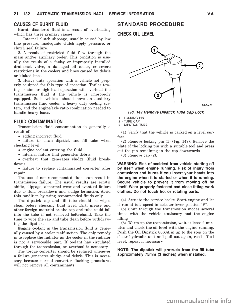
(2) Remove locking pin (1) (Fig. 149). Remove the
plate of the locking pin with a suitable tool and press
out the pin remaining in the cap downwards.
(3) Remove cap (2).
WARNING: Risk of accident from vehicle starting off
by itself when engine running. Risk of injury from
contusions and burns if you insert your hands into
the engine when it is started or when it is running.
Secure vehicle to prevent it from moving off by
itself. Wear properly fastened and close-fitting work
clothes. Do not touch hot or rotating parts.
(4) Actuate the service brake. Start engine and let
it run at idle speed in selector lever position ªPº.
(5) Shift through the transmission modes several
times with the vehicle stationary and the engine
idling
(6) Warm up the transmission, wait at least 2 min-
utes and check the oil level with the engine running.
Push the Oil Dipstick 8863A in up to the stop on the
electrohydraulic unit and pull out again, read off oil
level, repeat if necessary.
NOTE: The dipstick will protrude from the fill tube
approximately 75mm (3 inches) when installed.
Fig. 149 Remove Dipstick Tube Cap Lock
1 - LOCKING PIN
2 - TUBE CAP
3 - DIPSTICK TUBE
21 - 132 AUTOMATIC TRANSMISSION NAG1 - SERVICE INFORMATIONVA
Page 1927 of 2305
INSTALLATION
Check converter hub and drive flats for sharp
edges, burrs, scratches, or nicks. Polish the hub and
flats with 320/400 grit paper or crocus cloth if neces-
sary. The hub must be smooth to avoid damaging the
pump seal at installation.
(1) Lubricate oil pump seal lip with transmission
fluid.
(2)
Place torque converter in position on transmission.
CAUTION: Do not damage oil pump seal or con-
verter hub while inserting torque converter into the
front of the transmission.
(3) Align torque converter to oil pump seal open-
ing.
(4) Insert torque converter hub into oil pump.
(5) While pushing torque converter inward, rotate
converter until converter is fully seated in the oil
pump gears.
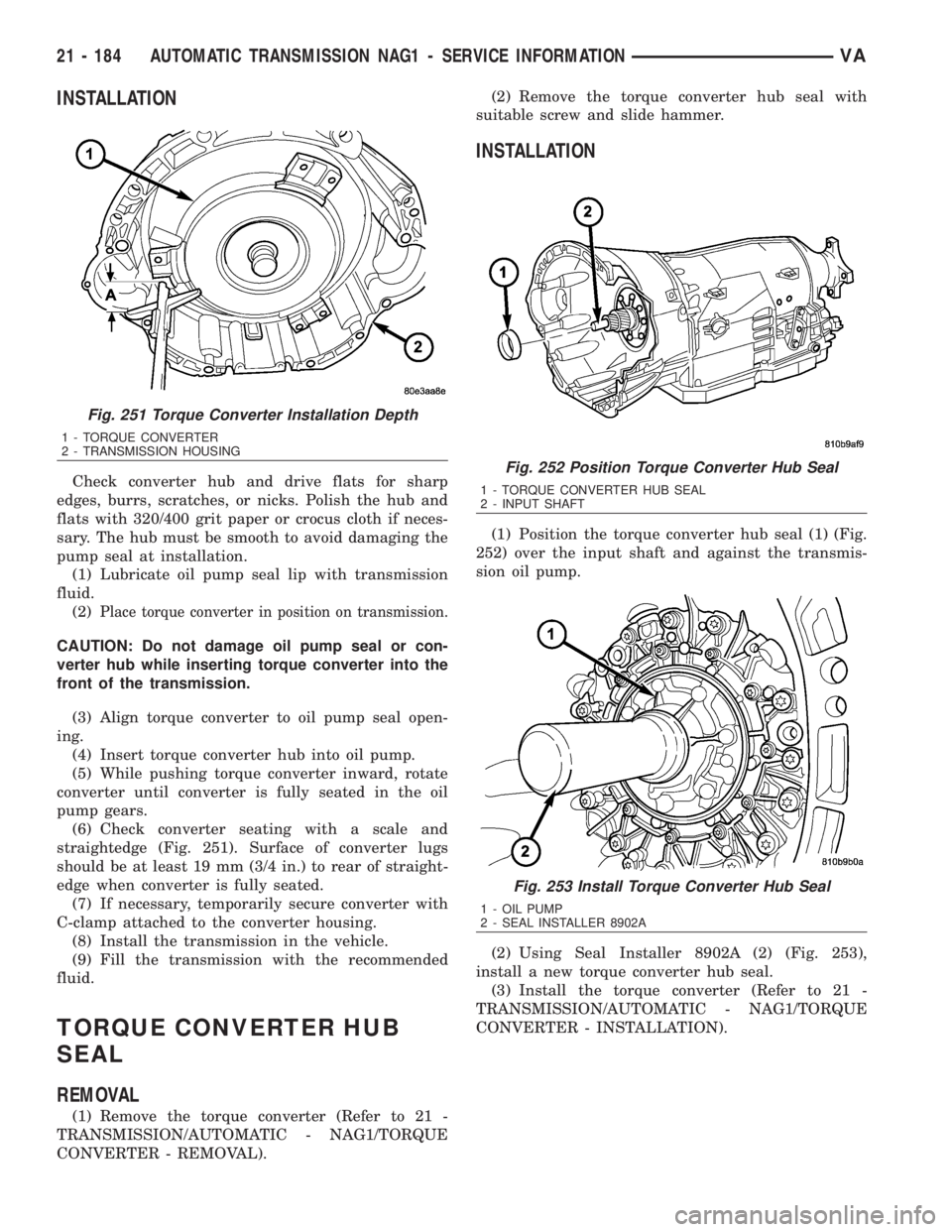
(6) Check converter seating with a scale and
straightedge (Fig. 251). Surface of converter lugs
should be at least 19 mm (3/4 in.) to rear of straight-
edge when converter is fully seated.
(7) If necessary, temporarily secure converter with
C-clamp attached to the converter housing.
(8) Install the transmission in the vehicle.
(9) Fill the transmission with the recommended
fluid.
TORQUE CONVERTER HUB
SEAL
REMOVAL
(1) Remove the torque converter (Refer to 21 -
TRANSMISSION/AUTOMATIC - NAG1/TORQUE
CONVERTER - REMOVAL).(2) Remove the torque converter hub seal with
suitable screw and slide hammer.
INSTALLATION
(1) Position the torque converter hub seal (1) (Fig.
252) over the input shaft and against the transmis-
sion oil pump.
(2) Using Seal Installer 8902A (2) (Fig. 253),
install a new torque converter hub seal.
(3) Install the torque converter (Refer to 21 -
TRANSMISSION/AUTOMATIC - NAG1/TORQUE
CONVERTER - INSTALLATION).
Fig. 251 Torque Converter Installation Depth
1 - TORQUE CONVERTER
2 - TRANSMISSION HOUSING
Fig. 252 Position Torque Converter Hub Seal
1 - TORQUE CONVERTER HUB SEAL
2 - INPUT SHAFT
Fig. 253 Install Torque Converter Hub Seal
1 - OIL PUMP
2 - SEAL INSTALLER 8902A
21 - 184 AUTOMATIC TRANSMISSION NAG1 - SERVICE INFORMATIONVA