2006 MERCEDES-BENZ SPRINTER wheel bolt torque
[x] Cancel search: wheel bolt torquePage 726 of 2305
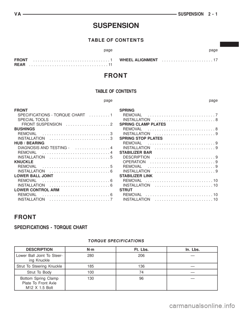
SUSPENSION
TABLE OF CONTENTS
page page
FRONT.................................1
REAR..................................11WHEEL ALIGNMENT......................17
FRONT
TABLE OF CONTENTS
page page
FRONT
SPECIFICATIONS - TORQUE CHART.........1
SPECIAL TOOLS
FRONT SUSPENSION...................2
BUSHINGS
REMOVAL.............................3
INSTALLATION..........................3
HUB / BEARING
DIAGNOSIS AND TESTING -...............4
REMOVAL.............................4
INSTALLATION..........................5
KNUCKLE
REMOVAL.............................5
INSTALLATION..........................6
LOWER BALL JOINT
REMOVAL.............................6
INSTALLATION..........................6
LOWER CONTROL ARM
REMOVAL.............................6
INSTALLATION..........................7SPRING
REMOVAL.............................7
INSTALLATION..........................8
SPRING CLAMP PLATES
REMOVAL.............................8
INSTALLATION..........................9
SPRING STOP PLATES
REMOVAL.............................9
INSTALLATION..........................9
STABILIZER BAR
DESCRIPTION..........................9
OPERATION............................9
REMOVAL.............................9
INSTALLATION..........................9
STABILIZER LINK
REMOVAL.............................10
INSTALLATION.........................10
STRUT
REMOVAL.............................10
INSTALLATION.........................10
FRONT
SPECIFICATIONS - TORQUE CHART
TORQUE SPECIFICATIONS
DESCRIPTION N´m Ft. Lbs. In. Lbs.
Lower Ball Joint To Steer-
ing Knuckle280 206 Ð
Strut To Steering Knuckle 185 136 Ð
Strut To Body 100 74 Ð
Bottom Spring Clamp
Plate To Front Axle
M12 X 1.5 Bolt130 96 Ð
VASUSPENSION 2 - 1
Page 747 of 2305
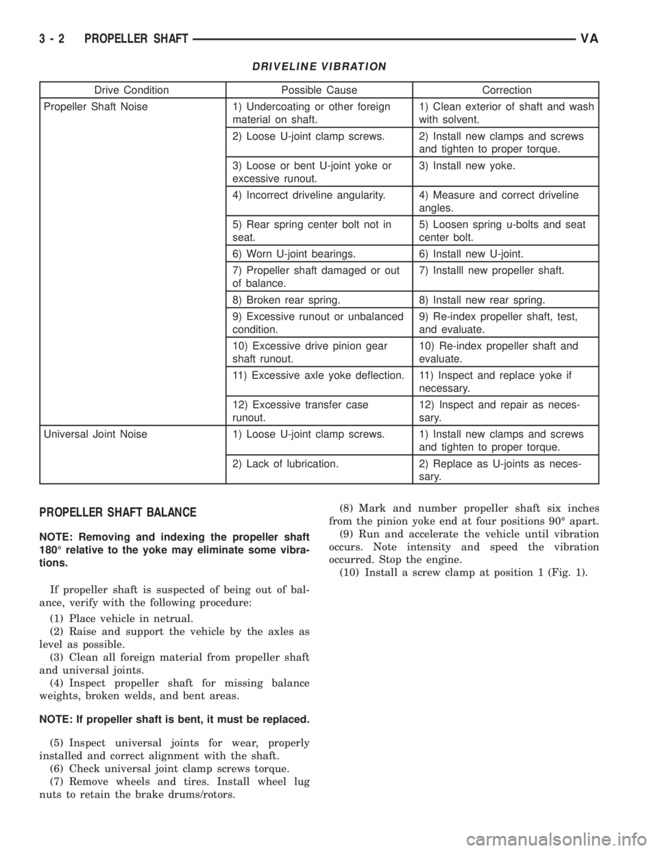
DRIVELINE VIBRATION
Drive Condition Possible Cause Correction
Propeller Shaft Noise 1) Undercoating or other foreign
material on shaft.1) Clean exterior of shaft and wash
with solvent.
2) Loose U-joint clamp screws. 2) Install new clamps and screws
and tighten to proper torque.
3) Loose or bent U-joint yoke or
excessive runout.3) Install new yoke.
4) Incorrect driveline angularity. 4) Measure and correct driveline
angles.
5) Rear spring center bolt not in
seat.5) Loosen spring u-bolts and seat
center bolt.
6) Worn U-joint bearings. 6) Install new U-joint.
7) Propeller shaft damaged or out
of balance.7) Installl new propeller shaft.
8) Broken rear spring. 8) Install new rear spring.
9) Excessive runout or unbalanced
condition.9) Re-index propeller shaft, test,
and evaluate.
10) Excessive drive pinion gear
shaft runout.10) Re-index propeller shaft and
evaluate.
11) Excessive axle yoke deflection. 11) Inspect and replace yoke if
necessary.
12) Excessive transfer case
runout.12) Inspect and repair as neces-
sary.
Universal Joint Noise 1) Loose U-joint clamp screws. 1) Install new clamps and screws
and tighten to proper torque.
2) Lack of lubrication. 2) Replace as U-joints as neces-
sary.
PROPELLER SHAFT BALANCE
NOTE: Removing and indexing the propeller shaft
180É relative to the yoke may eliminate some vibra-
tions.
If propeller shaft is suspected of being out of bal-
ance, verify with the following procedure:
(1) Place vehicle in netrual.
(2) Raise and support the vehicle by the axles as
level as possible.
(3) Clean all foreign material from propeller shaft
and universal joints.
(4) Inspect propeller shaft for missing balance
weights, broken welds, and bent areas.
NOTE: If propeller shaft is bent, it must be replaced.
(5) Inspect universal joints for wear, properly
installed and correct alignment with the shaft.
(6) Check universal joint clamp screws torque.
(7) Remove wheels and tires. Install wheel lug
nuts to retain the brake drums/rotors.(8) Mark and number propeller shaft six inches
from the pinion yoke end at four positions 90É apart.
(9) Run and accelerate the vehicle until vibration
occurs. Note intensity and speed the vibration
occurred. Stop the engine.
(10) Install a screw clamp at position 1 (Fig. 1).
3 - 2 PROPELLER SHAFTVA
Page 794 of 2305
(4) Open up bleeder, then have a helper press
down the brake pedal. Once the pedal is down closethe bleeder. Repeat bleeding until fluid stream is
clear and free of bubbles. Then move to the next
wheel.
STANDARD PROCEDURE - PRESSURE BLEED-
ING
Use approved brake fluid (Refer to LUBRICATION
& MAINTENANCE/FLUID TYPES - DESCRIP-
TION). Use fresh, clean fluid from a sealed container
at all times.
Follow the manufacturers instructions carefully
when using pressure equipment. Do not exceed the
tank manufacturers pressure recommendations. Gen-
erally, a tank pressure of 15-20 psi is sufficient for
bleeding.
Fill the bleeder tank with recommended fluid and
purge air from the tank lines before bleeding.
Do not pressure bleed without a proper master cyl-
inder adapter. The wrong adapter can lead to leak-
age, or drawing air back into the system.
HYDRAULIC / MECHANICAL
SPECIFICATIONS
SPECIFICATIONS - TORQUE CHART
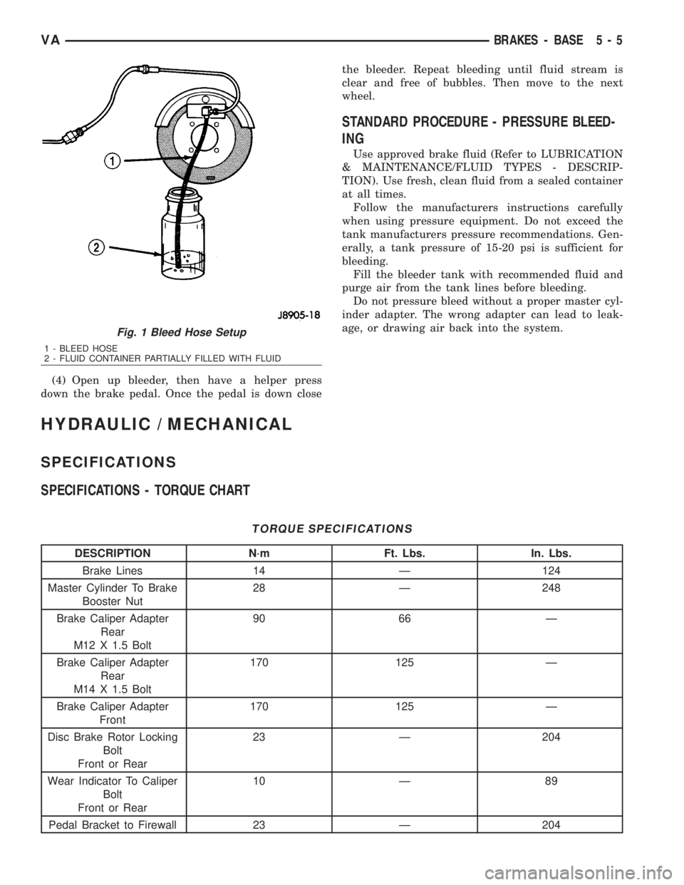
TORQUE SPECIFICATIONS
DESCRIPTION N´m Ft. Lbs. In. Lbs.
Brake Lines 14 Ð 124
Master Cylinder To Brake
Booster Nut28 Ð 248
Brake Caliper Adapter
Rear
M12 X 1.5 Bolt90 66 Ð
Brake Caliper Adapter
Rear
M14 X 1.5 Bolt170 125 Ð
Brake Caliper Adapter
Front170 125 Ð
Disc Brake Rotor Locking
Bolt
Front or Rear23 Ð 204
Wear Indicator To Caliper
Bolt
Front or Rear10 Ð 89
Pedal Bracket to Firewall 23 Ð 204
Fig. 1 Bleed Hose Setup
1 - BLEED HOSE
2 - FLUID CONTAINER PARTIALLY FILLED WITH FLUID
VABRAKES - BASE 5 - 5
Page 1576 of 2305
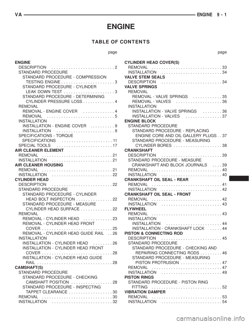
ENGINE
TABLE OF CONTENTS
page page
ENGINE
DESCRIPTION..........................2
STANDARD PROCEDURE
STANDARD PROCEDURE - COMPRESSION
TESTING ENGINE......................3
STANDARD PROCEDURE - CYLINDER
LEAK DOWN TEST.....................3
STANDARD PROCEDURE - DETERMINING
CYLINDER PRESSURE LOSS.............4
REMOVAL
REMOVAL - ENGINE COVER.............4
REMOVAL............................5
INSTALLATION
INSTALLATION - ENGINE COVER..........9
INSTALLATION........................9
SPECIFICATIONS - TORQUE
SPECIFICATIONS.....................11
SPECIAL TOOLS.......................17
AIR CLEANER ELEMENT
REMOVAL.............................21
INSTALLATION.........................21
AIR CLEANER HOUSING
REMOVAL.............................21
INSTALLATION.........................22
CYLINDER HEAD
DESCRIPTION.........................22
STANDARD PROCEDURE
STANDARD PROCEDURE - CYLINDER
HEAD BOLT INSPECTION...............22
STANDARD PROCEDURE - MEASURE
CYLINDER HEAD SURFACE.............22
REMOVAL
REMOVAL - CYLINDER HEAD............23
REMOVAL - CYLINDER HEAD FRONT
COVER.............................25
REMOVAL - CYLINDER HEAD GUIDE RAIL . . 26
INSTALLATION
INSTALLATION - CYLINDER HEAD........26
INSTALLATION - CYLINDER HEAD FRONT
COVER.............................28
INSTALLATION - CYLINDER HEAD GUIDE
RAIL...............................28
CAMSHAFT(S)
STANDARD PROCEDURE
STANDARD PROCEDURE - CHECKING
CAMSHAFT POSITION.................28
STANDARD PROCEDURE - INSPECTING
TAPPET CLEARANCE..................30
REMOVAL.............................30
INSTALLATION.........................32CYLINDER HEAD COVER(S)
REMOVAL.............................33
INSTALLATION.........................34
VALVE STEM SEALS
DESCRIPTION.........................34
VALVE SPRINGS
REMOVAL
REMOVAL - VALVE SPRINGS............35
REMOVAL - VALVES...................36
INSTALLATION
INSTALLATION - VALVE SPRINGS........36
INSTALLATION - VALVES...............37
ENGINE BLOCK
STANDARD PROCEDURE
STANDARD PROCEDURE - REPLACING
ENGINE CORE AND OIL GALLERY PLUGS . . 37
STANDARD PROCEDURE - MEASURING
CYLINDER BORES....................38
CRANKSHAFT
DESCRIPTION.........................39
STANDARD PROCEDURE - MEASURE
CRANKSHAFT AND BLOCK JOURNALS....39
REMOVAL.............................40
INSTALLATION.........................40
CRANKSHAFT OIL SEAL - REAR
REMOVAL.............................41
INSTALLATION.........................42
CRANKSHAFT OIL SEAL - FRONT
REMOVAL.............................42
INSTALLATION.........................43
FLYWHEEL
REMOVAL.............................43
INSTALLATION
INSTALLATION.......................44
INSTALLATION - CRANKSHAFT LOCK.....44
PISTON & CONNECTING ROD
DESCRIPTION.........................45
STANDARD PROCEDURE
STANDARD PROCEDURE - CHECKING AND
REPAIRING CONNECTING RODS.........46
STANDARD PROCEDURE - MEASURING
PISTON PROTRUSION.................47
REMOVAL.............................47
INSTALLATION.........................49
PISTON RINGS
STANDARD PROCEDURE - PISTON RING
FITTING.............................52
VIBRATION DAMPER
REMOVAL.............................53
INSTALLATION.........................54
VAENGINE 9 - 1
Page 1587 of 2305
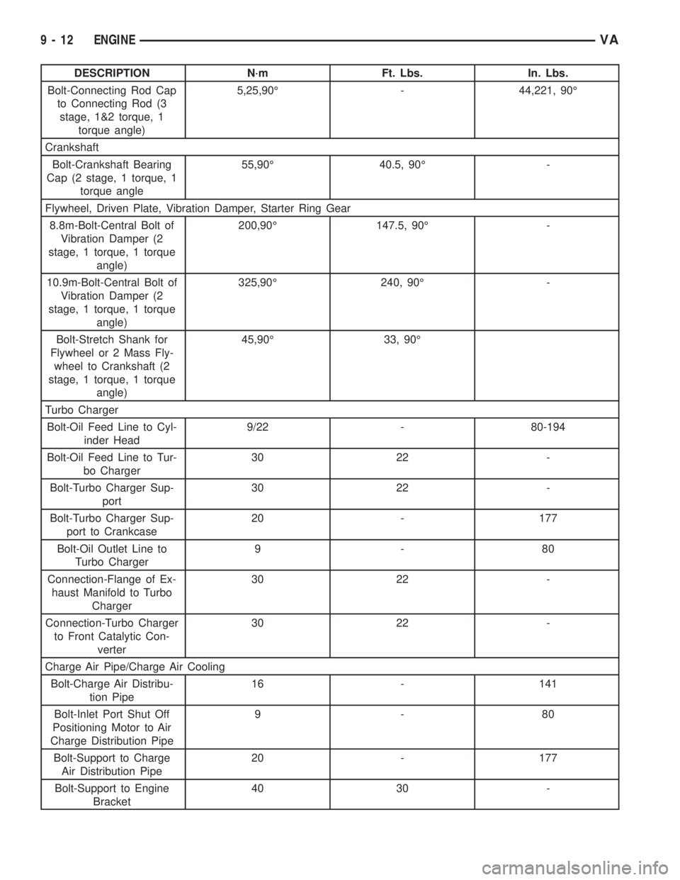
DESCRIPTION N´m Ft. Lbs. In. Lbs.
Bolt-Connecting Rod Cap
to Connecting Rod (3
stage, 1&2 torque, 1
torque angle)5,25,90É - 44,221, 90É
Crankshaft
Bolt-Crankshaft Bearing
Cap (2 stage, 1 torque, 1
torque angle55,90É 40.5, 90É -
Flywheel, Driven Plate, Vibration Damper, Starter Ring Gear
8.8m-Bolt-Central Bolt of
Vibration Damper (2
stage, 1 torque, 1 torque
angle)200,90É 147.5, 90É -
10.9m-Bolt-Central Bolt of
Vibration Damper (2
stage, 1 torque, 1 torque
angle)325,90É 240, 90É -
Bolt-Stretch Shank for
Flywheel or 2 Mass Fly-
wheel to Crankshaft (2
stage, 1 torque, 1 torque
angle)45,90É 33, 90É
Turbo Charger
Bolt-Oil Feed Line to Cyl-
inder Head9/22 - 80-194
Bolt-Oil Feed Line to Tur-
bo Charger30 22 -
Bolt-Turbo Charger Sup-
port30 22 -
Bolt-Turbo Charger Sup-
port to Crankcase20 - 177
Bolt-Oil Outlet Line to
Turbo Charger9-80
Connection-Flange of Ex-
haust Manifold to Turbo
Charger30 22 -
Connection-Turbo Charger
to Front Catalytic Con-
verter30 22 -
Charge Air Pipe/Charge Air Cooling
Bolt-Charge Air Distribu-
tion Pipe16 - 141
Bolt-Inlet Port Shut Off
Positioning Motor to Air
Charge Distribution Pipe9-80
Bolt-Support to Charge
Air Distribution Pipe20 - 177
Bolt-Support to Engine
Bracket40 30 -
9 - 12 ENGINEVA
Page 1619 of 2305
INSTALLATION
INSTALLATION
NOTE: A flex rod torque wrench must not be used
in order to avoid angle errors when tightening to
degrees.
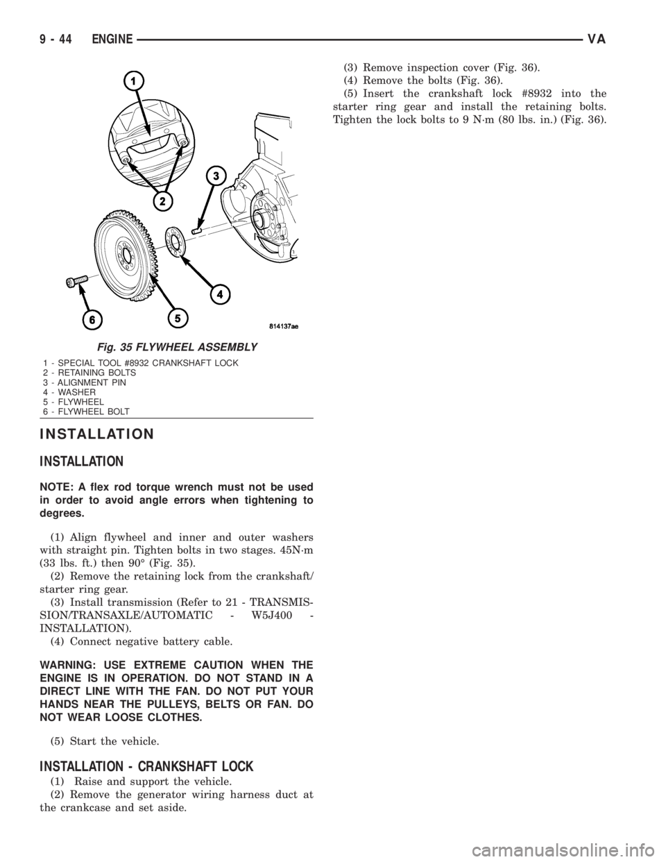
(1) Align flywheel and inner and outer washers
with straight pin. Tighten bolts in two stages. 45N´m
(33 lbs. ft.) then 90É (Fig. 35).
(2) Remove the retaining lock from the crankshaft/
starter ring gear.
(3) Install transmission (Refer to 21 - TRANSMIS-
SION/TRANSAXLE/AUTOMATIC - W5J400 -
INSTALLATION).
(4) Connect negative battery cable.
WARNING: USE EXTREME CAUTION WHEN THE
ENGINE IS IN OPERATION. DO NOT STAND IN A
DIRECT LINE WITH THE FAN. DO NOT PUT YOUR
HANDS NEAR THE PULLEYS, BELTS OR FAN. DO
NOT WEAR LOOSE CLOTHES.
(5) Start the vehicle.
INSTALLATION - CRANKSHAFT LOCK
(1) Raise and support the vehicle.
(2) Remove the generator wiring harness duct at
the crankcase and set aside.(3) Remove inspection cover (Fig. 36).
(4) Remove the bolts (Fig. 36).
(5) Insert the crankshaft lock #8932 into the
starter ring gear and install the retaining bolts.
Tighten the lock bolts to 9 N´m (80 lbs. in.) (Fig. 36).
Fig. 35 FLYWHEEL ASSEMBLY
1 - SPECIAL TOOL #8932 CRANKSHAFT LOCK
2 - RETAINING BOLTS
3 - ALIGNMENT PIN
4 - WASHER
5 - FLYWHEEL
6 - FLYWHEEL BOLT
9 - 44 ENGINEVA
Page 1733 of 2305
COLUMN
TABLE OF CONTENTS
page page
COLUMN
SPECIFICATIONS - TORQUE CHART.........4
INTERMEDIATE SHAFT
REMOVAL.............................4
INSTALLATION..........................5
KEY/LOCK CYLINDER
REMOVAL.............................5INSTALLATION..........................6
STEERING WHEEL
REMOVAL.............................6
INSTALLATION..........................6
COLUMN
SPECIFICATIONS - TORQUE CHART
TORQUE SPECIFICATIONS
DESCRIPTION N´m Ft. Lbs. In. Lbs.
Steering Wheel With Air-
bag To Steering Shaft80 59 Ð
Jacket Tube For Steering
Shaft To Waist Rail25 18 221
U-Joint To Steering Gear
Shaft24 18 212
INTERMEDIATE SHAFT
REMOVAL
(1) Disconnect the ground cable from the battery.
(2) Remove the air bag module from the steering
wheel.
(3) Turn the steering wheel and lock the steering
wheel in the straight ahead position.The position
of the steering gear must not be altered again
for the entire duration of the work procedure.
(4) Remove the electrical center.
(5) Remove the steering wheel bolt.
(6) Remove the steering wheel from the steering
column.
(7) Remove the clockspring.Unscrew the retain-
ing bolts just enough to be able to remove the
clockspring. Do not twist or disassemble the
clockspring.
(8) Remove the combination switch.
(9) Disconnect the electrical connector for the igni-
tion lock.
(10) Remove the spring for the brake pedal from
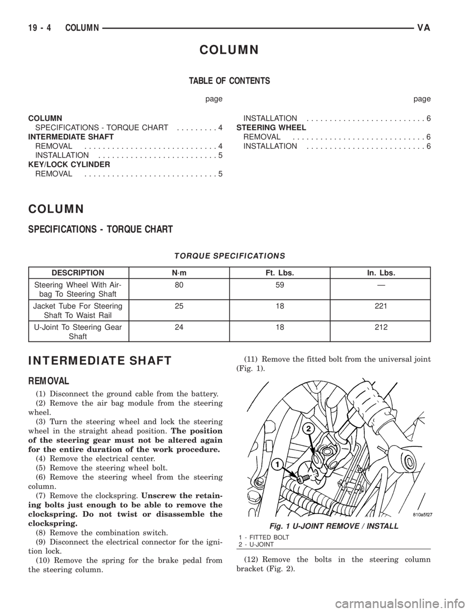
the steering column.(11) Remove the fitted bolt from the universal joint
(Fig. 1).
(12) Remove the bolts in the steering column
bracket (Fig. 2).
Fig. 1 U-JOINT REMOVE / INSTALL
1 - FITTED BOLT
2 - U-JOINT
19 - 4 COLUMNVA
Page 1736 of 2305
GEAR
TABLE OF CONTENTS
page page
GEAR
DESCRIPTION..........................7
REMOVAL.............................7INSTALLATION..........................7
SPECIFICATIONS - TORQUE CHART.........8
GEAR
DESCRIPTION
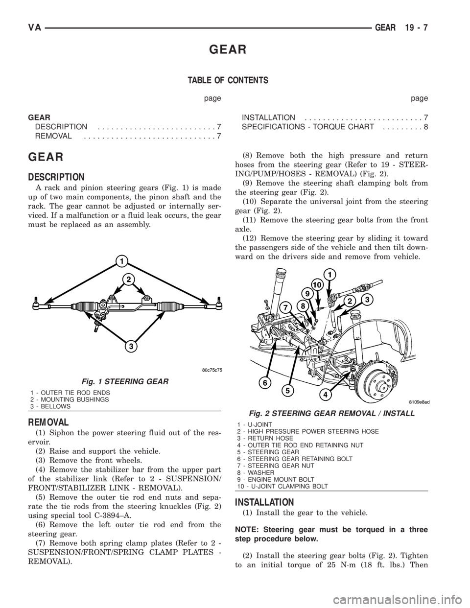
A rack and pinion steering gears (Fig. 1) is made
up of two main components, the pinon shaft and the
rack. The gear cannot be adjusted or internally ser-
viced. If a malfunction or a fluid leak occurs, the gear
must be replaced as an assembly.
REMOVAL
(1) Siphon the power steering fluid out of the res-
ervoir.
(2) Raise and support the vehicle.
(3) Remove the front wheels.
(4) Remove the stabilizer bar from the upper part
of the stabilizer link (Refer to 2 - SUSPENSION/
FRONT/STABILIZER LINK - REMOVAL).
(5) Remove the outer tie rod end nuts and sepa-
rate the tie rods from the steering knuckles (Fig. 2)
using special tool C-3894±A.
(6) Remove the left outer tie rod end from the
steering gear.
(7) Remove both spring clamp plates (Refer to 2 -
SUSPENSION/FRONT/SPRING CLAMP PLATES -
REMOVAL).(8) Remove both the high pressure and return
hoses from the steering gear (Refer to 19 - STEER-
ING/PUMP/HOSES - REMOVAL) (Fig. 2).
(9) Remove the steering shaft clamping bolt from
the steering gear (Fig. 2).
(10) Separate the universal joint from the steering
gear (Fig. 2).
(11) Remove the steering gear bolts from the front
axle.
(12) Remove the steering gear by sliding it toward
the passengers side of the vehicle and then tilt down-
ward on the drivers side and remove from vehicle.
INSTALLATION
(1) Install the gear to the vehicle.
NOTE: Steering gear must be torqued in a three
step procedure below.
(2) Install the steering gear bolts (Fig. 2). Tighten
to an initial torque of 25 N´m (18 ft. lbs.) Then
Fig. 1 STEERING GEAR
1 - OUTER TIE ROD ENDS
2 - MOUNTING BUSHINGS
3 - BELLOWS
Fig. 2 STEERING GEAR REMOVAL / INSTALL
1 - U-JOINT
2 - HIGH PRESSURE POWER STEERING HOSE
3 - RETURN HOSE
4 - OUTER TIE ROD END RETAINING NUT
5 - STEERING GEAR
6 - STEERING GEAR RETAINING BOLT
7 - STEERING GEAR NUT
8 - WASHER
9 - ENGINE MOUNT BOLT
10 - U-JOINT CLAMPING BOLT
VAGEAR 19 - 7