2006 MERCEDES-BENZ SPRINTER jack points
[x] Cancel search: jack pointsPage 720 of 2305

Do not blend other specific fuel additives with die-
sel fuel. They only result in unnecessary cost, and
may be harmful to the engine operation.
POWER STEERING FLUID
No fluid service required. Filled with Power Steer-
ing Fluid approved to MB 236.3, such as Mobil
ATF-D (Exxon Mobil Corporation) or equivalent.
OPERATION - AUTOMATIC TRANSMISSION
FLUID
The automatic transmission fluid is selected based
upon several qualities. The fluid must provide a high
level of protection for the internal components by
providing a lubricating film between adjacent metal
components. The fluid must also be thermally stable
so that it can maintain a consistent viscosity through
a large temperature range. If the viscosity stays con-
stant through the temperature range of operation,
transmission operation and shift feel will remain con-
sistent. Transmission fluid must also be a good con-
ductor of heat. The fluid must absorb heat from the
internal transmission components and transfer that
heat to the transmission case.
FLUID CAPACITIES
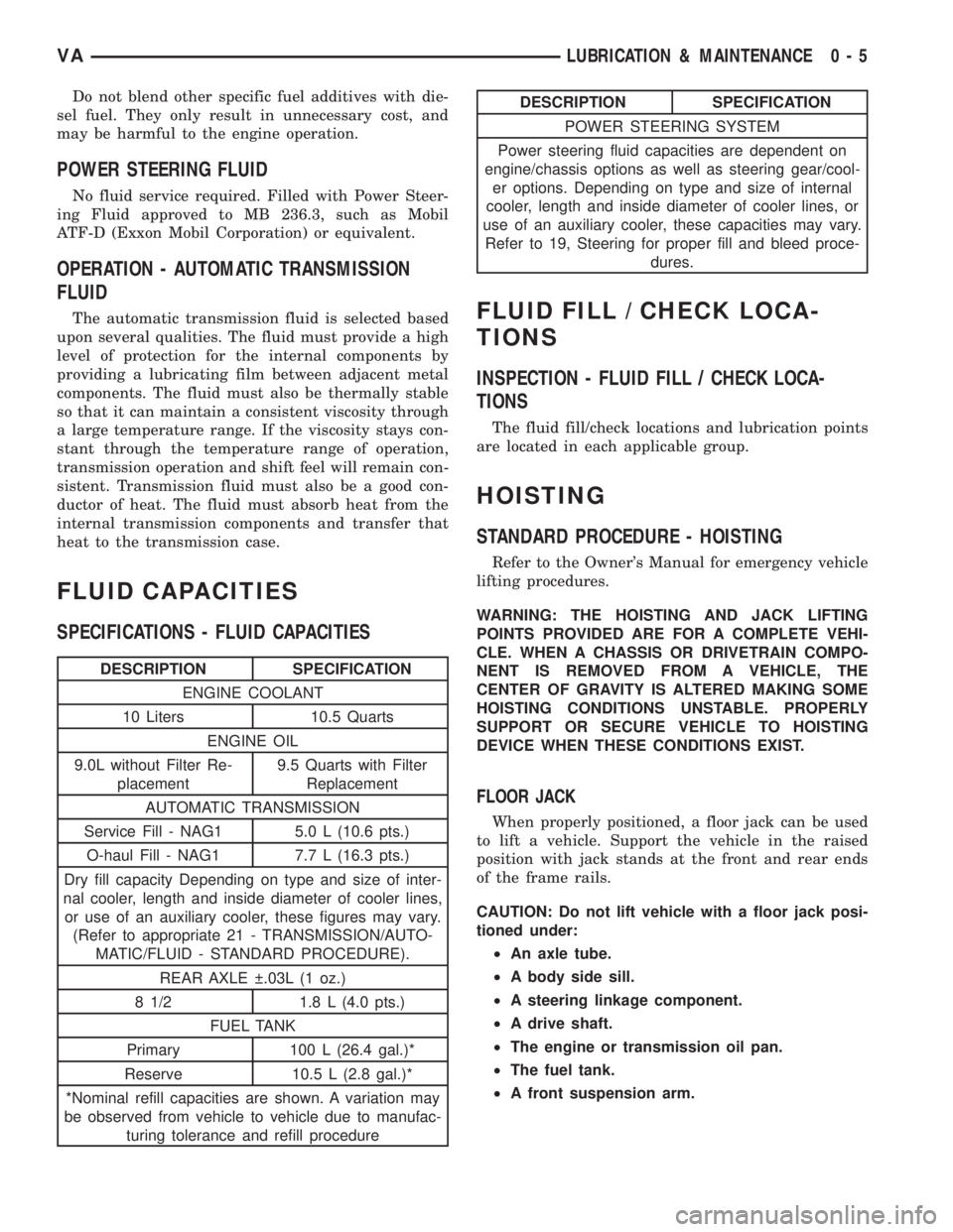
SPECIFICATIONS - FLUID CAPACITIES
DESCRIPTION SPECIFICATION
ENGINE COOLANT
10 Liters 10.5 Quarts
ENGINE OIL
9.0L without Filter Re-
placement9.5 Quarts with Filter
Replacement
AUTOMATIC TRANSMISSION
Service Fill - NAG1 5.0 L (10.6 pts.)
O-haul Fill - NAG1 7.7 L (16.3 pts.)
Dry fill capacity Depending on type and size of inter-
nal cooler, length and inside diameter of cooler lines,
or use of an auxiliary cooler, these figures may vary.
(Refer to appropriate 21 - TRANSMISSION/AUTO-
MATIC/FLUID - STANDARD PROCEDURE).
REAR AXLE .03L (1 oz.)
8 1/2 1.8 L (4.0 pts.)
FUEL TANK
Primary 100 L (26.4 gal.)*
Reserve 10.5 L (2.8 gal.)*
*Nominal refill capacities are shown. A variation may
be observed from vehicle to vehicle due to manufac-
turing tolerance and refill procedure
DESCRIPTION SPECIFICATION
POWER STEERING SYSTEM
Power steering fluid capacities are dependent on
engine/chassis options as well as steering gear/cool-
er options. Depending on type and size of internal
cooler, length and inside diameter of cooler lines, or
use of an auxiliary cooler, these capacities may vary.
Refer to 19, Steering for proper fill and bleed proce-
dures.
FLUID FILL / CHECK LOCA-
TIONS
INSPECTION - FLUID FILL / CHECK LOCA-
TIONS
The fluid fill/check locations and lubrication points
are located in each applicable group.
HOISTING
STANDARD PROCEDURE - HOISTING
Refer to the Owner's Manual for emergency vehicle
lifting procedures.
WARNING: THE HOISTING AND JACK LIFTING
POINTS PROVIDED ARE FOR A COMPLETE VEHI-
CLE. WHEN A CHASSIS OR DRIVETRAIN COMPO-
NENT IS REMOVED FROM A VEHICLE, THE
CENTER OF GRAVITY IS ALTERED MAKING SOME
HOISTING CONDITIONS UNSTABLE. PROPERLY
SUPPORT OR SECURE VEHICLE TO HOISTING
DEVICE WHEN THESE CONDITIONS EXIST.
FLOOR JACK
When properly positioned, a floor jack can be used
to lift a vehicle. Support the vehicle in the raised
position with jack stands at the front and rear ends
of the frame rails.
CAUTION: Do not lift vehicle with a floor jack posi-
tioned under:
²An axle tube.
²A body side sill.
²A steering linkage component.
²A drive shaft.
²The engine or transmission oil pan.
²The fuel tank.
²A front suspension arm.
VALUBRICATION & MAINTENANCE 0 - 5
Page 734 of 2305

(5) Remove the spring clamp plate and rubber
block.
(6) Remove the shear bushings from the front and
rear bolts.
INSTALLATION
(1) Install a jack under the lower ball joint and
lower the weight of the vehicle enough to allow a
wrench between the lower control arm and the
bracket tighten the nut.
(2) Fit one spring clamp plate together with the
lower spring rubber block.
(3) Install the bolt with the shear bushing on the
rear mounting,Do not tighten yet.
(4) Install the four retaining bolts for the spring
clamp plate. Tighten to 65 N´m (48 ft.lbs.).
(5) Align the holes for the front clamp plate joint
using a suitable drift (shear bushing not installed).
(6) Remove the alignment drift.
(7) Insert the shear bushing and retaining bolt
into the hole and tighten to 130 N´m (96 ft.lbs.).
(8) Remove the jack and lower the vehicle.
SPRING STOP PLATES
REMOVAL
(1) Raise and support the vehicle.
(2) Remove the tire and wheel assembly.
(3) Remove the lower end of the stabilizer link
from the stop plate.
(4) Remove the three bolts retaining the spring
stop plate from the lower control arm.
INSTALLATION
(1) Install the spring stop plate to the lower con-
trol arm. Tighten the bolts to 60 N´m (44 ft. lbs.).
(2) Install the stabilizer link to the spring stop
plate.
(3) Install the tire and wheel assembly.
(4) Lower the vehicle.
STABILIZER BAR
DESCRIPTION
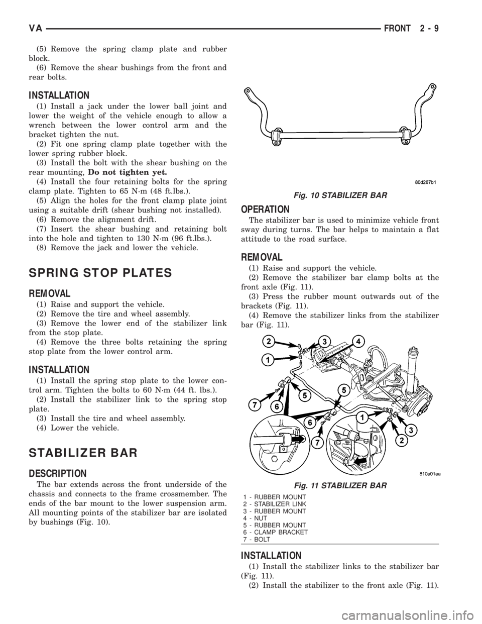
The bar extends across the front underside of the
chassis and connects to the frame crossmember. The
ends of the bar mount to the lower suspension arm.
All mounting points of the stabilizer bar are isolated
by bushings (Fig. 10).
OPERATION
The stabilizer bar is used to minimize vehicle front
sway during turns. The bar helps to maintain a flat
attitude to the road surface.
REMOVAL
(1) Raise and support the vehicle.
(2) Remove the stabilizer bar clamp bolts at the
front axle (Fig. 11).
(3) Press the rubber mount outwards out of the
brackets (Fig. 11).
(4) Remove the stabilizer links from the stabilizer
bar (Fig. 11).
INSTALLATION
(1) Install the stabilizer links to the stabilizer bar
(Fig. 11).
(2) Install the stabilizer to the front axle (Fig. 11).
Fig. 10 STABILIZER BAR
Fig. 11 STABILIZER BAR
1 - RUBBER MOUNT
2 - STABILIZER LINK
3 - RUBBER MOUNT
4 - NUT
5 - RUBBER MOUNT
6 - CLAMP BRACKET
7 - BOLT
VAFRONT 2 - 9
Page 879 of 2305

INSTALLATION
(1) Install the battery hold down brackets.
(2) Install the two nuts that secure the battery
hold down brackets to the battery tray. Tighten to 70
in. lbs.
BATTERY CABLES
DESCRIPTION
The battery cables are large gauge, stranded cop-
per wires sheathed within a heavy plastic or syn-
thetic rubber insulating jacket. The wire used in the
battery cables combines excellent flexibility and reli-
ability with high electrical current carrying capacity.
The battery cables cannot be repaired and, if dam-
aged or faulty they must be replaced. Both the bat-
tery positive and negative cables are available for
service replacement only as a unit with the battery
positive cable wire harness or the battery negative
cable wire harness, which may include portions of
the wiring circuits for the generator and other com-
ponents on some models.
The battery cables feature a stamped brass clamp-
ing type female battery terminal crimped onto one
end of the battery cable wire and then solder-dipped.
A square headed pinch-bolt and hex nut are installed
at the open end of the female battery terminal clamp.
The battery positive cable also includes a red molded
rubber protective cover for the female battery termi-
nal clamp. Large eyelet type terminals are crimped
onto the opposite end of the battery cable wire and
then solder-dipped. The battery positive cable wires
have a red insulating jacket to provide visual identi-
fication and feature a larger female battery terminal
clamp to allow connection to the larger battery posi-
tive terminal post. The battery negative cable wires
have a black insulating jacket and a smaller female
battery terminal clamp.
OPERATION
The battery cables connect the battery terminal
posts to the vehicle electrical system. These cables
also provide a return path for electrical current gen-
erated by the charging system for restoring the volt-
age potential of the battery. The female battery
terminal clamps on the ends of the battery cable
wires provide a strong and reliable connection of the
battery cable to the battery terminal posts. The ter-
minal pinch bolts allow the female terminal clamps
to be tightened around the male terminal posts on
the top of the battery. The eyelet terminals secured
to the ends of the battery cable wires opposite the
female battery terminal clamps provide secure and
reliable connection of the battery to the vehicle elec-
trical system.
DIAGNOSIS AND TESTING - BATTERY CABLES
A voltage drop test will determine if there is exces-
sive resistance in the battery cable terminal connec-
tions or the battery cables. If excessive resistance is
found in the battery cable connections, the connec-
tion point should be disassembled, cleaned of all cor-
rosion or foreign material, then reassembled.
Following reassembly, check the voltage drop for the
battery cable connection and the battery cable again
to confirm repair.
When performing the voltage drop test, it is impor-
tant to remember that the voltage drop is giving an
indication of the resistance between the two points at
which the voltmeter probes are attached.EXAM-
PLE:When testing the resistance of the battery pos-
itive cable, touch the voltmeter leads to the battery
positive cable terminal clamp and to the battery pos-
itive cable eyelet terminal at the starter solenoid
B(+) terminal stud. If you probe the battery positive
terminal post and the battery positive cable eyelet
terminal at the starter solenoid B(+) terminal stud,
you are reading the combined voltage drop in the
battery positive cable terminal clamp-to-terminal
post connection and the battery positive cable.
VOLTAGE DROP TEST
WARNING: IF THE BATTERY SHOWS SIGNS OF
FREEZING, LEAKING, LOOSE POSTS, OR LOW
ELECTROLYTE LEVEL, DO NOT TEST, ASSIST-
BOOST, OR CHARGE. THE BATTERY MAY ARC
INTERNALLY AND EXPLODE. PERSONAL INJURY
AND/OR VEHICLE DAMAGE MAY RESULT.
WARNING: EXPLOSIVE HYDROGEN GAS FORMS IN
AND AROUND THE BATTERY. DO NOT SMOKE,
USE FLAME, OR CREATE SPARKS NEAR THE BAT-
TERY. PERSONAL INJURY AND/OR VEHICLE DAM-
AGE MAY RESULT.
WARNING: THE BATTERY CONTAINS SULFURIC
ACID, WHICH IS POISONOUS AND CAUSTIC. AVOID
CONTACT WITH THE SKIN, EYES, OR CLOTHING.
IN THE EVENT OF CONTACT, FLUSH WITH WATER
AND CALL A PHYSICIAN IMMEDIATELY. KEEP OUT
OF THE REACH OF CHILDREN.
WARNING: IF THE BATTERY IS EQUIPPED WITH
REMOVABLE CELL CAPS, BE CERTAIN THAT EACH
OF THE CELL CAPS IS IN PLACE AND TIGHT
BEFORE THE BATTERY IS RETURNED TO SER-
VICE. PERSONAL INJURY AND/OR VEHICLE DAM-
AGE MAY RESULT FROM LOOSE OR MISSING
CELL CAPS.
8F - 14 BATTERY SYSTEMVA