2006 MERCEDES-BENZ SPRINTER motor specifications
[x] Cancel search: motor specificationsPage 322 of 2305

1.0 INTRODUCTION
The procedures contained in this manual include
all the specifications, instructions, and graphics
needed to diagnose the Sprinter Chassis system
problems: Bosch 5.7 ABS/ESP/TCS (ASR) Braking
System. The diagnostics in this manual are based
on the failure condition or symptom being present
at time of diagnosis.
Please follow the recommendations below when
choosing your diagnostic path.
1. First make sure the DRBIIItis communicating
with the vehicle system being diagnosed. If the
DRBIIItdisplays a ``No Response'' condition, you
must diagnose that first.
2. Read DTC's (diagnostic trouble codes) with the
DRBIIIt.
3. If no DTC's are present, identify the customer
complaint.
4. Once the DTC or customer complaint is iden-
tified locate the matching test in the Table of
Contents and begin to diagnose the system.
All component location views are in Section 8.0.
All connector pinouts are in Section 9.0. All sche-
matics are in Section 10.0.
When repairs are required, refer to the appropri-
ate service manual for the proper removal and
repair procedure.
Diagnostic procedures change every year. New
diagnostic systems may be added; carryover sys-
tems maybe enhanced. READ THIS MANUAL BE-
FORE TRYING TO DIAGNOSE A VEHICLE DI-
AGNOSTIC TROUBLE CODE. It is recommended
that you review the entire manual to become famil-
iar with all new and changed diagnostic procedures.
This manual reflects many suggested changes
from readers of past issues. After using this man-
ual, if you have any comments or recommendations,
please fill out the form at the back of the manual
and mail it back.
1.1 SYSTEM COVERAGE
This diagnostic procedure manual covers the An-
tilock Braking System (ABS), the Electronic Stabil-
ity Program (ESP) and the Traction Control System
(TCS) found on the Sprinter.
1.2 SIX-STEP TROUBLESHOOTING
PROCEDURE
Diagnosis of the Antilock Brake Systems is done
in six basic steps:
²Verification of complaint
²Verification of any related symptoms
²Symptom analysis
²Problem isolation
²Repair of isolated problem
²Verification of proper operation
2.0 INDENTIFICATION OF
SYSTEM
The Bosch 5.7 system can be identified by the 42
way Controller Antilock Brake (CAB), Hydraulic
Control Unit (HCU) and Pump Motor being an
integral electronic/hydraulic unit mounted below
the Master Cylinder with four Wheel Speed Sen-
sors, one at each wheel.
Vehicles with the Traction Control System (TCS/
ASR) can be identified by the presence of the
Traction Control System Switch (TCCS) located on
the center instrument panel.
Vehicles with Electronic Stability Program (ESP)
can be identified by the presence of the Steering
Angle Sensor and the Lateral Acceleration/Yaw
Sensor.
3.0 SYSTEM DESCRIPTION AND
FUNCTIONAL OPERATION
3.1 ESP
The ESP system consists of the electronic control/
hydraulic unit, steering angle sensor, lateral
acceleration/yaw sensor and wheel speed sensors.
When the vehicle is in a turn, the ESP looks at the
steering wheel angle sensor value and monitors the
wheel speed of the inner and outer wheels to ensure
the values are plausible. The steering angle sensor
also measures the speed at which the steering
wheel is turned.
The ESP control module is very similar to the
ABS/ASR module. The ESP is comprised of several
other systems, namely theHBA, ABS, TCS (ASR),
EBDandFZRsystems.
3.2 ABS
The Controller Antilock Brake (CAB) is used to
monitor wheel speeds and modulates (controls) hy-
draulic pressure in each brake channel. The modu-
lated hydraulic pressure is used to prevent wheel
lock up during braking and maintain vehicle stabil-
ity. The CAB also provides a vehicle speed signal
(VSS) to the Electronic Control Module (ECM).
During a non-ABS stop, the system functions as a
standard braking system. The CAB uses special
sortware that monitors the wheel speed(s) and
when certain criteria are met, the software will
1
GENERAL INFORMATION
Page 325 of 2305

read opposite switch states.Note: The BS and
BLS are in the same switch housing.
BRAKE LAMP SWITCH (BLS):This switch pre-
pares the CAB for a possible antilock event. The
CAB uses an output state voltage from the BLS
when the brake pedal is either depressed/released.
The Fused Ignition Switch Output circuit supplies
12 volts to the BLS. A depressed brake pedal will
close the BLS circuit and the BLS Output circuit
supplies 12 volts at the CAB. When the driver
releases the brake pedal, the BLS Output circuit
voltage drops to 0 volts and the CAB senses the
brake pedal state. This tells the CAB what position
the brake pedal is currently in to make an ABS
event possible. When using the DRBIIItin Inputs/
Outputs, the BS and BLS will read opposite switch
states.Note: The BS and BLS are in the same
switch housing.
TRACTION CONTROL SYSTEM SWITCH
(TCSS):This switch signals the CAB to either turn
ON or OFF the TCS. The driver can toggle the
TCSS, which receives 12 volts from the D (+) Relay
Output circuit. Depending on the position of the
TCSS, open or closed, the CAB receives the TCSS
state voltage on the TCS Switch Sense circuit.
When 12 volts are applied to the TCS Switch Sense
circuit, the TCS is OFF. When no voltage is present,
the TCS is ON.
WHEEL SPEED SENSORS AND TONE
WHEELS:The Bosch 5.7 system uses one passive
WSS on each wheel. The sensor measures the wheel
speed by monitoring a rotating tone wheel. As the
teeth of the tone wheel move through the magnetic
field of the sensor an AC voltage and amperage is
generated. This signal frequency increases or de-
creases proportionally to the speed of the wheel.
The CAB monitors this signal to check for a sudden
change in single or multiple wheel decelerations. If
the deceleration of one or more wheels is not within
a predetermined amount, the CAB takes control for
antilock action through the HCU. Each WSS has a
magnetic inductive pick up coil (WSS) that is
mounted to a fixed component. There is an air gap
between the tone wheel and the speed sensor as-
sembly. Diagnostically, the coils of the Wheel Speed
Sensors have the same amount of resistance. When
measured across the CAB harness connector termi-
nals, the resistance should be between 1100 - 1800
ohms. Refer to service manual for WSS replacement
and air gap specifications.
Correct ABS operation is dependent on Tone
Wheel speed signal from the WSS. The vehicle
wheels and tires should all be the same size and
type to get accurate signals. In addition, all tires
should be at recommended tire pressures.3.7.5 SELF TESTS
The system software includes several self tests
that are performed every time the ignition is turned
on and the vehicle is driven. Some of the self tests
occur immediately, while others occur under normal
driving conditions while not in antilock operation.
The CAB checks continuously for a missing or
erratic WSS signals/circuits, tone wheels, solenoids,
pump motor or solenoid relay by performing several
tests such as: dynamic, static, ohmic, voltage drop,
and timed response. If any component exhibits a
fault during testing, the CAB will request to illumi-
nate the ABS and TCS warning indicators.
As an additional check of the ESP system, a road
test procedure is available on the DRBIIIt. This
test should be carried out when any ESP component
is replaced in order to ensure proper function. Since
the wheel speed sensors are required inputs to the
ESP, this test should also be performed if the wheel
speed sensors are replaced.
First, the brakes are applied with the vehicle
stationary. Then, the vehicle is driven at approxi-
mately 6 MPH. The driver has to make left and
right turns, with a minimum 90 degree steering
turning angle. If the indicator lamp goes out, every-
thing is in order. If the lamp remains illuminated,
the DRBIIItwill display the fault codes that are
causing the test to fail. The road test function is set
in the ESP control module, and can only be deacti-
vated once there are no more fault codes detected.
The Steering Angle Sensor must be initialized. A
procedure is carried out using the DRBIIItto
ensure that the module detects the exact position of
the sensor. The sensor must be calibrated any time
wheel alignment is changed, the steering column is
removed and re-installed, or the sensor is replaced.
3.8 USING THE DRBIIIT
Refer to the DRBIIItuser 's guide for instructions
and assistance with reading diagnostic trouble
codes, erasing diagnostic trouble codes and other
DRBIIItfunctions.
3.9 DRBIIITERROR MESSAGES
Under normal operation, the DRBIIItwill dis-
play one of only two error messages:
Ð User-Requested WARM Boot or User-Requested
COLD Boot.
If the DRBIIItshould display any other error
message, record the entire display and call the
STAR Center for information and assistance. This
is a sample of such an error message display:
4
GENERAL INFORMATION
Page 718 of 2305
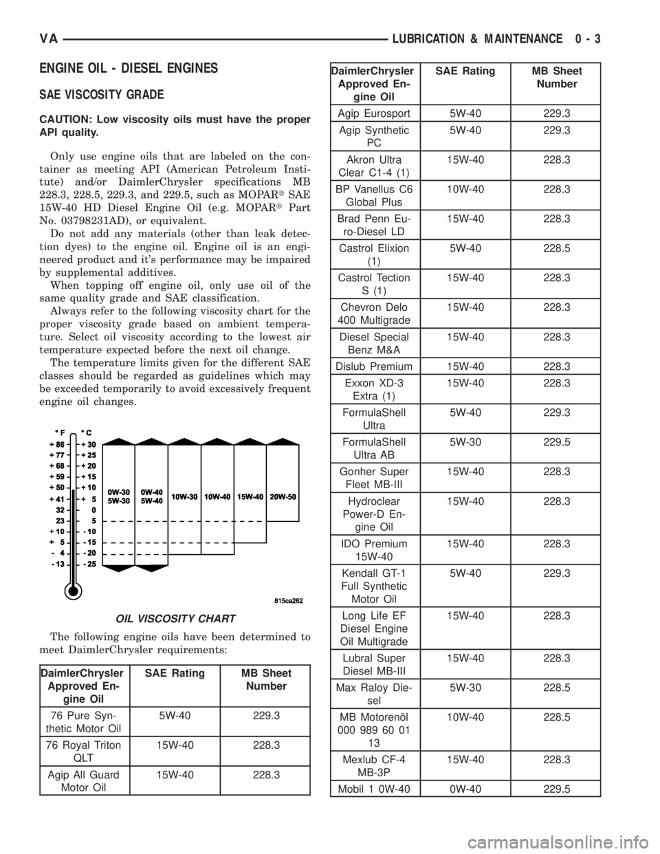
ENGINE OIL - DIESEL ENGINES
SAE VISCOSITY GRADE
CAUTION: Low viscosity oils must have the proper
API quality.
Only use engine oils that are labeled on the con-
tainer as meeting API (American Petroleum Insti-
tute) and/or DaimlerChrysler specifications MB
228.3, 228.5, 229.3, and 229.5, such as MOPARtSAE
15W-40 HD Diesel Engine Oil (e.g. MOPARtPart
No. 03798231AD), or equivalent.
Do not add any materials (other than leak detec-
tion dyes) to the engine oil. Engine oil is an engi-
neered product and it's performance may be impaired
by supplemental additives.
When topping off engine oil, only use oil of the
same quality grade and SAE classification.
Always refer to the following viscosity chart for the
proper viscosity grade based on ambient tempera-
ture. Select oil viscosity according to the lowest air
temperature expected before the next oil change.
The temperature limits given for the different SAE
classes should be regarded as guidelines which may
be exceeded temporarily to avoid excessively frequent
engine oil changes.
The following engine oils have been determined to
meet DaimlerChrysler requirements:
DaimlerChrysler
Approved En-
gine OilSAE Rating MB Sheet
Number
76 Pure Syn-
thetic Motor Oil5W-40 229.3
76 Royal Triton
QLT15W-40 228.3
Agip All Guard
Motor Oil15W-40 228.3
DaimlerChrysler
Approved En-
gine OilSAE Rating MB Sheet
Number
Agip Eurosport 5W-40 229.3
Agip Synthetic
PC5W-40 229.3
Akron Ultra
Clear C1-4 (1)15W-40 228.3
BP Vanellus C6
Global Plus10W-40 228.3
Brad Penn Eu-
ro-Diesel LD15W-40 228.3
Castrol Elixion
(1)5W-40 228.5
Castrol Tection
S (1)15W-40 228.3
Chevron Delo
400 Multigrade15W-40 228.3
Diesel Special
Benz M&A15W-40 228.3
Dislub Premium 15W-40 228.3
Exxon XD-3
Extra (1)15W-40 228.3
FormulaShell
Ultra5W-40 229.3
FormulaShell
Ultra AB5W-30 229.5
Gonher Super
Fleet MB-III15W-40 228.3
Hydroclear
Power-D En-
gine Oil15W-40 228.3
IDO Premium
15W-4015W-40 228.3
Kendall GT-1
Full Synthetic
Motor Oil5W-40 229.3
Long Life EF
Diesel Engine
Oil Multigrade15W-40 228.3
Lubral Super
Diesel MB-III15W-40 228.3
Max Raloy Die-
sel5W-30 228.5
MB Motorenæl
000 989 60 01
1310W-40 228.5
Mexlub CF-4
MB-3P15W-40 228.3
Mobil 1 0W-40 0W-40 229.5
OIL VISCOSITY CHART
VALUBRICATION & MAINTENANCE 0 - 3
Page 893 of 2305

STARTING SYSTEM
TABLE OF CONTENTS
page page
STARTING SYSTEM
DESCRIPTION.........................28
OPERATION...........................28
DIAGNOSIS AND TESTING - STARTING
SYSTEM............................29
SPECIFICATIONS
TORQUE - STARTER - DIESEL...........33
SPECIFICATIONS - STARTER MOTOR -
DIESEL.............................33STARTER MOTOR
DIAGNOSIS AND TESTING - STARTER
MOTOR .............................33
REMOVAL.............................34
INSTALLATION.........................35
STARTER MOTOR RELAY
DESCRIPTION.........................35
REMOVAL.............................35
INSTALLATION.........................36
STARTING SYSTEM
DESCRIPTION
The starting system consists of:
²Starter relay
²Starter motor (including an integral starter sole-
noid)
Other components to be considered as part of start-
ing system are:
²Battery
²Battery cables
²Ignition switch and key lock cylinder
²Park/neutral position switch (automatic trans-
mission)
²Wire harnesses and connections.
The Battery, Starting, and Charging systems oper-
ate in conjunction with one another, and must be
tested as a complete system. For correct operation of
starting/charging systems, all components used in
these 3 systems must perform within specifications.
When attempting to diagnose any of these systems, it
is important that you keep their interdependency in
mind.
The diagnostic procedures used in each of these
groups include the most basic conventional diagnostic
methods, to the more sophisticated On-Board Diag-
nostics (OBD) built into the Engine Control Module
(ECM). Use of an induction-type milliampere amme-
ter, volt/ohmmeter, battery charger, carbon pile rheo-
stat (load tester), and 12-volt test lamp may be
required.
Certain starting system components are monitored
by the ECM and may produce a Diagnostic Trouble
Code (DTC).
OPERATION
The starting system components form two separate
circuits. A high-amperage feed circuit that feeds the
starter motor high-amperage, and a low-amperagecontrol circuit that operates on less than 20 amperes.
The high-amperage feed circuit components include
the battery, the battery cables, the contact disc por-
tion of the starter solenoid, and the starter motor
itself. The low-amperage control circuit components
include the ignition switch, the park/neutral position
switch (automatic transmission), the starter relay,
the electromagnetic windings of the starter solenoid,
and the connecting wire harness components.
If the vehicle is equipped with an automatic trans-
mission, battery voltage is supplied through the low-
amperage control circuit to the coil battery terminal
of the starter relay when the ignition switch is
turned to the momentary Start position. The park/
neutral position switch is installed in series between
the starter relay coil ground terminal and ground.
This normally open switch prevents the starter relay
from being energized and the starter motor from
operating unless the automatic transmission gear
selector is in the Neutral or Park positions.
When the starter relay coil is energized, the nor-
mally open relay contacts close. The relay contacts
connect the relay common feed terminal to the relay
normally open terminal. The closed relay contacts
energize the starter solenoid coil windings.
The energized solenoid pull-in coil pulls in the sole-
noid plunger. The solenoid plunger pulls the shift
lever in the starter motor. This engages the starter
overrunning clutch and pinion gear with the starter
ring gear on the manual transmission flywheel or on
the automatic transmission torque converter or
torque converter drive plate.
As the solenoid plunger reaches the end of its
travel, the solenoid contact disc completes the high-
amperage starter feed circuit and energizes the sole-
noid plunger hold-in coil. Current now flows between
the solenoid battery terminal and the starter motor,
energizing the starter.
Once the engine starts, the overrunning clutch pro-
tects the starter motor from damage by allowing the
8F - 28 STARTING SYSTEMVA
Page 894 of 2305
starter pinion gear to spin faster than the pinion
shaft. When the driver releases the ignition switch to
the On position, the starter relay coil is de-energized.
This causes the relay contacts to open. When the
relay contacts open, the starter solenoid plunger
hold-in coil is de-energized.
When the solenoid plunger hold-in coil is de-ener-
gized, the solenoid plunger return spring returns the
plunger to its relaxed position. This causes the con-
tact disc to open the starter feed circuit, and the shift
lever to disengage the overrunning clutch and pinion
gear from the starter ring gear.DIAGNOSIS AND TESTING - STARTING SYS-
TEM
The battery, starting, and charging systems oper-
ate in conjunction with one another, and must be
tested as a complete system. For correct starting/
charging system operation, all of the components
involved in these 3 systems must perform within
specifications.
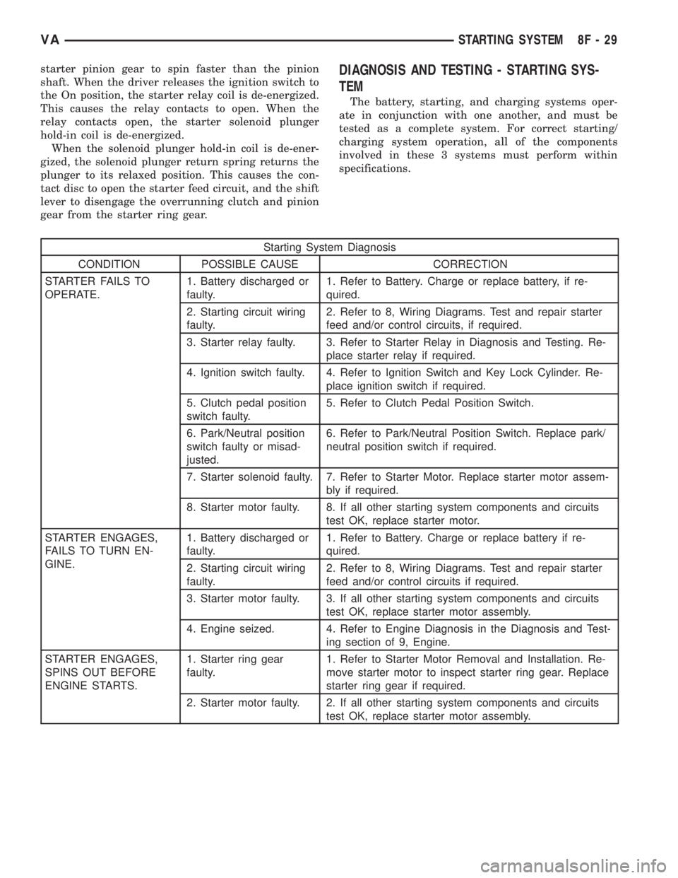
Starting System Diagnosis
CONDITION POSSIBLE CAUSE CORRECTION
STARTER FAILS TO
OPERATE.1. Battery discharged or
faulty.1. Refer to Battery. Charge or replace battery, if re-
quired.
2. Starting circuit wiring
faulty.2. Refer to 8, Wiring Diagrams. Test and repair starter
feed and/or control circuits, if required.
3. Starter relay faulty. 3. Refer to Starter Relay in Diagnosis and Testing. Re-
place starter relay if required.
4. Ignition switch faulty. 4. Refer to Ignition Switch and Key Lock Cylinder. Re-
place ignition switch if required.
5. Clutch pedal position
switch faulty.5. Refer to Clutch Pedal Position Switch.
6. Park/Neutral position
switch faulty or misad-
justed.6. Refer to Park/Neutral Position Switch. Replace park/
neutral position switch if required.
7. Starter solenoid faulty. 7. Refer to Starter Motor. Replace starter motor assem-
bly if required.
8. Starter motor faulty. 8. If all other starting system components and circuits
test OK, replace starter motor.
STARTER ENGAGES,
FAILS TO TURN EN-
GINE.1. Battery discharged or
faulty.1. Refer to Battery. Charge or replace battery if re-
quired.
2. Starting circuit wiring
faulty.2. Refer to 8, Wiring Diagrams. Test and repair starter
feed and/or control circuits if required.
3. Starter motor faulty. 3. If all other starting system components and circuits
test OK, replace starter motor assembly.
4. Engine seized. 4. Refer to Engine Diagnosis in the Diagnosis and Test-
ing section of 9, Engine.
STARTER ENGAGES,
SPINS OUT BEFORE
ENGINE STARTS.1. Starter ring gear
faulty.1. Refer to Starter Motor Removal and Installation. Re-
move starter motor to inspect starter ring gear. Replace
starter ring gear if required.
2. Starter motor faulty. 2. If all other starting system components and circuits
test OK, replace starter motor assembly.
VASTARTING SYSTEM 8F - 29
Page 895 of 2305
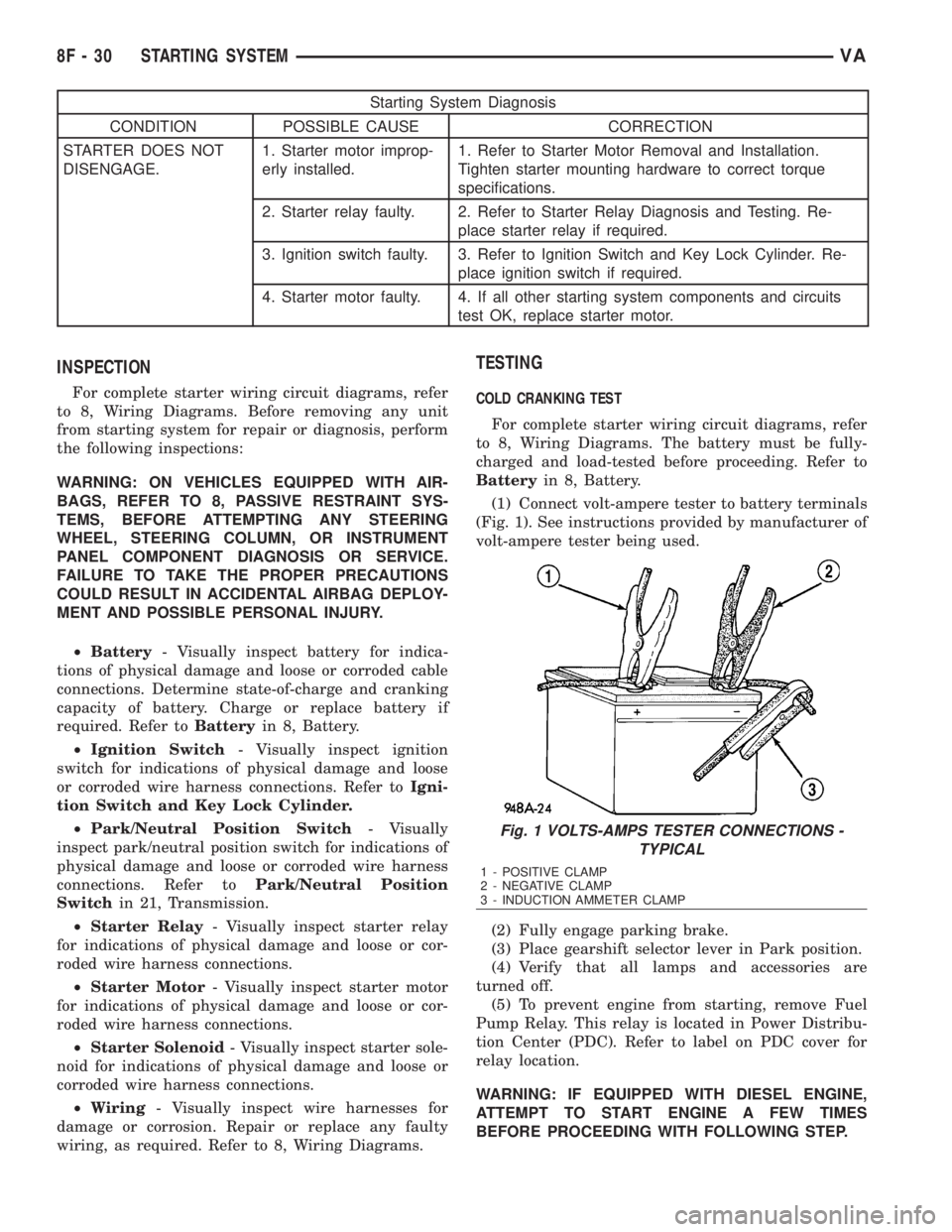
Starting System Diagnosis
CONDITION POSSIBLE CAUSE CORRECTION
STARTER DOES NOT
DISENGAGE.1. Starter motor improp-
erly installed.1. Refer to Starter Motor Removal and Installation.
Tighten starter mounting hardware to correct torque
specifications.
2. Starter relay faulty. 2. Refer to Starter Relay Diagnosis and Testing. Re-
place starter relay if required.
3. Ignition switch faulty. 3. Refer to Ignition Switch and Key Lock Cylinder. Re-
place ignition switch if required.
4. Starter motor faulty. 4. If all other starting system components and circuits
test OK, replace starter motor.
INSPECTION
For complete starter wiring circuit diagrams, refer
to 8, Wiring Diagrams. Before removing any unit
from starting system for repair or diagnosis, perform
the following inspections:
WARNING: ON VEHICLES EQUIPPED WITH AIR-
BAGS, REFER TO 8, PASSIVE RESTRAINT SYS-
TEMS, BEFORE ATTEMPTING ANY STEERING
WHEEL, STEERING COLUMN, OR INSTRUMENT
PANEL COMPONENT DIAGNOSIS OR SERVICE.
FAILURE TO TAKE THE PROPER PRECAUTIONS
COULD RESULT IN ACCIDENTAL AIRBAG DEPLOY-
MENT AND POSSIBLE PERSONAL INJURY.
²Battery- Visually inspect battery for indica-
tions of physical damage and loose or corroded cable
connections. Determine state-of-charge and cranking
capacity of battery. Charge or replace battery if
required. Refer toBatteryin 8, Battery.
²Ignition Switch- Visually inspect ignition
switch for indications of physical damage and loose
or corroded wire harness connections. Refer toIgni-
tion Switch and Key Lock Cylinder.
²Park/Neutral Position Switch- Visually
inspect park/neutral position switch for indications of
physical damage and loose or corroded wire harness
connections. Refer toPark/Neutral Position
Switchin 21, Transmission.
²Starter Relay- Visually inspect starter relay
for indications of physical damage and loose or cor-
roded wire harness connections.
²Starter Motor- Visually inspect starter motor
for indications of physical damage and loose or cor-
roded wire harness connections.
²Starter Solenoid- Visually inspect starter sole-
noid for indications of physical damage and loose or
corroded wire harness connections.
²Wiring- Visually inspect wire harnesses for
damage or corrosion. Repair or replace any faulty
wiring, as required. Refer to 8, Wiring Diagrams.
TESTING
COLD CRANKING TEST
For complete starter wiring circuit diagrams, refer
to 8, Wiring Diagrams. The battery must be fully-
charged and load-tested before proceeding. Refer to
Batteryin 8, Battery.
(1) Connect volt-ampere tester to battery terminals
(Fig. 1). See instructions provided by manufacturer of
volt-ampere tester being used.
(2) Fully engage parking brake.
(3) Place gearshift selector lever in Park position.
(4) Verify that all lamps and accessories are
turned off.
(5) To prevent engine from starting, remove Fuel
Pump Relay. This relay is located in Power Distribu-
tion Center (PDC). Refer to label on PDC cover for
relay location.
WARNING: IF EQUIPPED WITH DIESEL ENGINE,
ATTEMPT TO START ENGINE A FEW TIMES
BEFORE PROCEEDING WITH FOLLOWING STEP.
Fig. 1 VOLTS-AMPS TESTER CONNECTIONS -
TYPICAL
1 - POSITIVE CLAMP
2 - NEGATIVE CLAMP
3 - INDUCTION AMMETER CLAMP
8F - 30 STARTING SYSTEMVA
Page 896 of 2305
(6) Rotate and hold ignition switch in Start posi-
tion. Note cranking voltage and current (amperage)
draw readings shown on volt-ampere tester.
(a) If voltage reads below 9.6 volts, refer to
Starter Motorin Diagnosis and Testing. If starter
motor is OK, refer toEngine Diagnosisin 9,
Engine for further testing of engine. If starter
motor is not OK, replace faulty starter motor.
(b) If voltage reads above 9.6 volts and current
(amperage) draw reads below specifications, refer
toFeed Circuit Testin this section.
(c) If voltage reads 12.5 volts or greater and
starter motor does not turn, refer toControl Cir-
cuit Testingin this section.
(d) If voltage reads 12.5 volts or greater and
starter motor turns very slowly, refer toFeed Cir-
cuit Testin this section.
NOTE: A cold engine will increase starter current
(amperage) draw reading, and reduce battery volt-
age reading.
FEED CIRCUIT TEST
The starter feed circuit test (voltage drop method)
will determine if there is excessive resistance in
high-amperage feed circuit. For complete starter wir-
ing circuit diagrams, refer 8, Wiring Diagrams.
When performing these tests, it is important to
remember that voltage drop is giving an indication of
resistance between two points at which voltmeter
probes are attached.
Example:When testing resistance of positive bat-
tery cable, touch voltmeter leads to positive battery
cable clamp and cable connector at starter solenoid.
If you probe positive battery terminal post and cable
connector at starter solenoid, you are reading com-
bined voltage drop in positive battery cable clamp-to-
terminal post connection and positive battery cable.
The following operation will require a voltmeter
accurate to 1/10 (0.10) volt. Before performing tests,
be certain that following procedures are accom-
plished:
²Battery is fully-charged and load-tested. Refer to
Batteryin 8, Battery.
²Fully engage parking brake.
²Place gearshift selector lever in Park position.
²Verify that all lamps and accessories are turned
off.
²To prevent engine from starting, remove Fuel
Pump Relay. This relay is located in Power Distribu-
tion Center (PDC). Refer to label on PDC cover for
relay location.
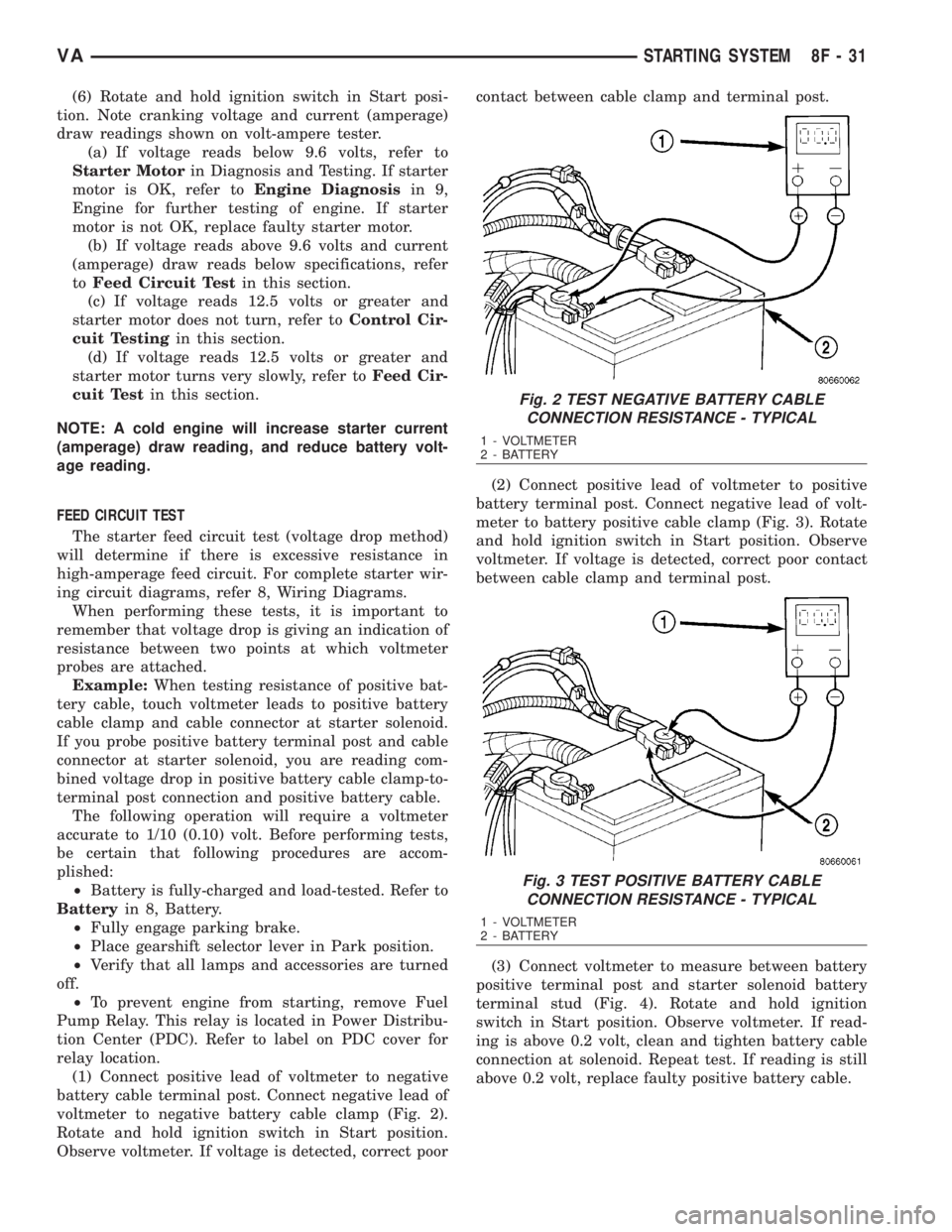
(1) Connect positive lead of voltmeter to negative
battery cable terminal post. Connect negative lead of
voltmeter to negative battery cable clamp (Fig. 2).
Rotate and hold ignition switch in Start position.
Observe voltmeter. If voltage is detected, correct poorcontact between cable clamp and terminal post.
(2) Connect positive lead of voltmeter to positive
battery terminal post. Connect negative lead of volt-
meter to battery positive cable clamp (Fig. 3). Rotate
and hold ignition switch in Start position. Observe
voltmeter. If voltage is detected, correct poor contact
between cable clamp and terminal post.
(3) Connect voltmeter to measure between battery
positive terminal post and starter solenoid battery
terminal stud (Fig. 4). Rotate and hold ignition
switch in Start position. Observe voltmeter. If read-
ing is above 0.2 volt, clean and tighten battery cable
connection at solenoid. Repeat test. If reading is still
above 0.2 volt, replace faulty positive battery cable.
Fig. 2 TEST NEGATIVE BATTERY CABLE
CONNECTION RESISTANCE - TYPICAL
1 - VOLTMETER
2 - BATTERY
Fig. 3 TEST POSITIVE BATTERY CABLE
CONNECTION RESISTANCE - TYPICAL
1 - VOLTMETER
2 - BATTERY
VASTARTING SYSTEM 8F - 31
Page 898 of 2305
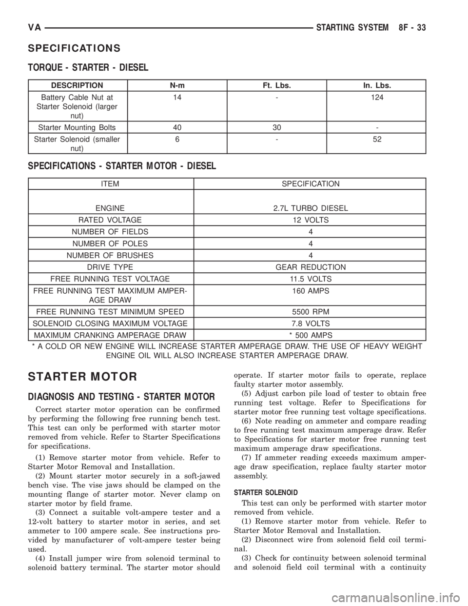
SPECIFICATIONS
TORQUE - STARTER - DIESEL
DESCRIPTION N-m Ft. Lbs. In. Lbs.
Battery Cable Nut at
Starter Solenoid (larger
nut)14 - 124
Starter Mounting Bolts 40 30 -
Starter Solenoid (smaller
nut)6-52
SPECIFICATIONS - STARTER MOTOR - DIESEL
ITEM SPECIFICATION
ENGINE 2.7L TURBO DIESEL
RATED VOLTAGE 12 VOLTS
NUMBER OF FIELDS 4
NUMBER OF POLES 4
NUMBER OF BRUSHES 4
DRIVE TYPE GEAR REDUCTION
FREE RUNNING TEST VOLTAGE 11.5 VOLTS
FREE RUNNING TEST MAXIMUM AMPER-
AGE DRAW160 AMPS
FREE RUNNING TEST MINIMUM SPEED 5500 RPM
SOLENOID CLOSING MAXIMUM VOLTAGE 7.8 VOLTS
MAXIMUM CRANKING AMPERAGE DRAW * 500 AMPS
* A COLD OR NEW ENGINE WILL INCREASE STARTER AMPERAGE DRAW. THE USE OF HEAVY WEIGHT
ENGINE OIL WILL ALSO INCREASE STARTER AMPERAGE DRAW.
STARTER MOTOR
DIAGNOSIS AND TESTING - STARTER MOTOR
Correct starter motor operation can be confirmed
by performing the following free running bench test.
This test can only be performed with starter motor
removed from vehicle. Refer to Starter Specifications
for specifications.
(1) Remove starter motor from vehicle. Refer to
Starter Motor Removal and Installation.
(2) Mount starter motor securely in a soft-jawed
bench vise. The vise jaws should be clamped on the
mounting flange of starter motor. Never clamp on
starter motor by field frame.
(3) Connect a suitable volt-ampere tester and a
12-volt battery to starter motor in series, and set
ammeter to 100 ampere scale. See instructions pro-
vided by manufacturer of volt-ampere tester being
used.
(4) Install jumper wire from solenoid terminal to
solenoid battery terminal. The starter motor shouldoperate. If starter motor fails to operate, replace
faulty starter motor assembly.
(5) Adjust carbon pile load of tester to obtain free
running test voltage. Refer to Specifications for
starter motor free running test voltage specifications.
(6) Note reading on ammeter and compare reading
to free running test maximum amperage draw. Refer
to Specifications for starter motor free running test
maximum amperage draw specifications.
(7) If ammeter reading exceeds maximum amper-
age draw specification, replace faulty starter motor
assembly.
STARTER SOLENOID
This test can only be performed with starter motor
removed from vehicle.
(1) Remove starter motor from vehicle. Refer to
Starter Motor Removal and Installation.
(2) Disconnect wire from solenoid field coil termi-
nal.
(3) Check for continuity between solenoid terminal
and solenoid field coil terminal with a continuity
VASTARTING SYSTEM 8F - 33