2006 MERCEDES-BENZ SPRINTER hood release
[x] Cancel search: hood releasePage 928 of 2305

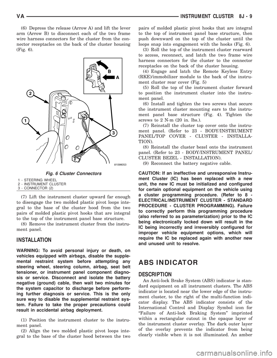
(6) Depress the release (Arrow A) and lift the lever
arm (Arrow B) to disconnect each of the two frame
wire harness connectors for the cluster from the con-
nector receptacles on the back of the cluster housing
(Fig. 6).
(7) Lift the instrument cluster upward far enough
to disengage the two molded plastic pivot loops inte-
gral to the base of the cluster hood from the two
pairs of molded plastic pivot hooks that are integral
to the top of the instrument panel base structure.
(8) Remove the instrument cluster from the instru-
ment panel.
INSTALLATION
WARNING: To avoid personal injury or death, on
vehicles equipped with airbags, disable the supple-
mental restraint system before attempting any
steering wheel, steering column, airbag, seat belt
tensioner, or instrument panel component diagno-
sis or service. Disconnect and isolate the battery
negative (ground) cable, then wait two minutes for
the system capacitor to discharge before perform-
ing further diagnosis or service. This is the only
sure way to disable the supplemental restraint sys-
tem. Failure to take the proper precautions could
result in accidental airbag deployment.
(1) Position the instrument cluster to the instru-
ment panel.
(2) Align the two molded plastic pivot loops inte-
gral to the base of the cluster hood between the twopairs of molded plastic pivot hooks that are integral
to the top of instrument panel base structure, then
push downward on the top of the cluster until the
loops snap into engagement with the hooks (Fig. 6).
(3) Roll the top of the instrument cluster rearward
to access, reconnect, and latch the two frame wire
harness connectors for the cluster to the connector
receptacles on the back of the cluster housing.
(4) Engage and latch the Remote Keyless Entry
(RKE)/immobilizer module to the back of the instru-
ment cluster rear cover (Fig. 5)
(5) Roll the top of the instrument cluster forward
to position the instrument cluster into the instru-
ment panel.
(6) Install and tighten the two screws that secure
the instrument cluster mounting ears to the instru-
ment panel base structure (Fig. 4). Tighten the
screws to 2 N´m (20 in. lbs.).
(7) Reinstall the cluster top cover onto the instru-
ment panel. (Refer to 23 - BODY/INSTRUMENT
PANEL/TOP COVER - CLUSTER - INSTALLA-
TION).
(8) Reinstall the cluster bezel onto the instrument
panel. (Refer to 23 - BODY/INSTRUMENT PANEL/
CLUSTER BEZEL - INSTALLATION).
(9) Reconnect the battery negative cable.
CAUTION: If an ineffective and unresponsive Instru-
ment Cluster (IC) has been replaced with a new
unit, the new IC must be initialized and configured
for certain optional equipment on the vehicle using
a cluster programming procedure. (Refer to 8 -
ELECTRICAL/INSTRUMENT CLUSTER - STANDARD
PROCEDURE - CLUSTER PROGRAMMING). Failure
to correctly perform this programming procedure
(also referred to as parameterization) prior to the IC
being electronically locked down will result in the
IC being incorrectly and irreversibly configured for
improper vehicle equipment options, which will
require the IC be replaced again with another new
and unused unit to resolve.
ABS INDICATOR
DESCRIPTION
An Anti-lock Brake System (ABS) indicator is stan-
dard equipment on all instrument clusters. The ABS
indicator is located near the lower edge of the instru-
ment cluster, to the right of the multi-function indi-
cator display. The ABS indicator consists of the
International Control and Display Symbol icon for
ªFailure of Anti-lock Braking Systemº imprinted
within a rectangular cutout in the opaque layer of
the instrument cluster overlay. The dark outer layer
of the overlay prevents the indicator from being
clearly visible when it is not illuminated. An amber
Fig. 6 Cluster Connectors
1 - STEERING WHEEL
2 - INSTRUMENT CLUSTER
3 - CONNECTOR (2)
VAINSTRUMENT CLUSTER 8J - 9
Page 998 of 2305

(1) Begin the cleanup by using a vacuum cleaner
to remove any residual powder from the vehicle inte-
rior. Clean from outside the vehicle and work your
way inside, so that you avoid kneeling or sitting on a
non-cleaned area.
(2) Be certain to vacuum the heater and air condi-
tioning outlets as well (Fig. 4). Run the heater and
air conditioner blower on the lowest speed setting
and vacuum any powder expelled from the outlets.
CAUTION: All damaged, faulty, or non-deployed
supplemental restraints which are replaced on vehi-
cles are to be handled and disposed of properly. If
an airbag unit or seat belt tensioner unit is faulty or
damaged and non-deployed, refer to the Hazardous
Substance Control System for proper disposal. Be
certain to dispose of all non-deployed and deployed
supplemental restraints in a manner consistent with
state, provincial, local and federal regulations.
(3) Next, remove the deployed supplemental
restraints from the vehicle. Refer to the appropriate
service removal procedures.
(4) You may need to vacuum the interior of the
vehicle a second time to recover all of the powder.
STANDARD PROCEDURE - VERIFICATION TEST
The following procedure should be performed using
a diagnostic scan tool to verify proper supplemental
restraint system operation following the service or
replacement of any supplemental restraint system
component.
WARNING: To avoid personal injury or death, on
vehicles equipped with airbags, disable the supple-
mental restraint system before attempting any
steering wheel, steering column, airbag, seat belt
tensioner, impact sensor, or instrument panel com-
ponent diagnosis or service. Disconnect and isolate
the battery negative (ground) cable, then wait two
minutes for the system capacitor to dischargebefore performing further diagnosis or service. This
is the only sure way to disable the supplemental
restraint system. Failure to take the proper precau-
tions could result in accidental airbag deployment.
(1) During the following test, the battery negative
cable remains disconnected and isolated, as it was
during the supplemental restraint system component
removal and installation procedures.
(2) Be certain that the diagnostic scan tool con-
tains the latest version of the proper diagnostic soft-
ware. Connect the diagnostic to the 16-way Data
Link Connector (DLC). The DLC is located on the
dash panel beneath the driver side lower edge of the
instrument panel, outboard of the steering column
(Fig. 5).
(3) Turn the ignition switch to the On position and
exit the vehicle with the diagnostic scan tool.
(4) Check to be certain that nobody is in the vehi-
cle, then reconnect the battery negative cable.
(5) Using the diagnostic, read and record the
active (current) Diagnostic Trouble Code (DTC) data.
(6) Next, use the diagnostic to read and record any
stored (historical) DTC data.
(7) If any DTC is found in Step 5 or Step 6, refer
to the appropriate diagnostic information.
(8) Use the diagnostic to erase the stored DTC
data. If any problems remain, the stored DTC data
will not erase. Refer to the appropriate diagnostic
information to diagnose any stored DTC that will not
erase. If the stored DTC information is successfully
erased, go to Step 9.
(9) Turn the ignition switch to the Off position for
about fifteen seconds, and then back to the On posi-
tion. Observe the airbag indicator in the instrument
cluster. It should illuminate for four seconds, and
then go out. This indicates that the supplemental
Fig. 4 Vacuum Heater and A/C Outlets - Typical
Fig. 5 16-Way Data Link Connector
1 - BOTTOM OF INSTRUMENT PANEL
2 - CONNECTOR COVER
3 - 16-WAY DATA LINK CONNECTOR
4 - DASH PANEL
5 - INSIDE HOOD RELEASE LEVER
VARESTRAINTS 8O - 7
Page 1992 of 2305

RADIATOR CROSSMEMBER
REMOVAL
(1) Remove grille. (Refer to 23 - BODY/EXTERI-
OR/GRILLE - REMOVAL)
(2) Remove headlamps. (Refer to 8 - ELECTRI-
CAL/LAMPS/LIGHTING - EXTERIOR/FRONT
LAMP UNIT - REMOVAL)
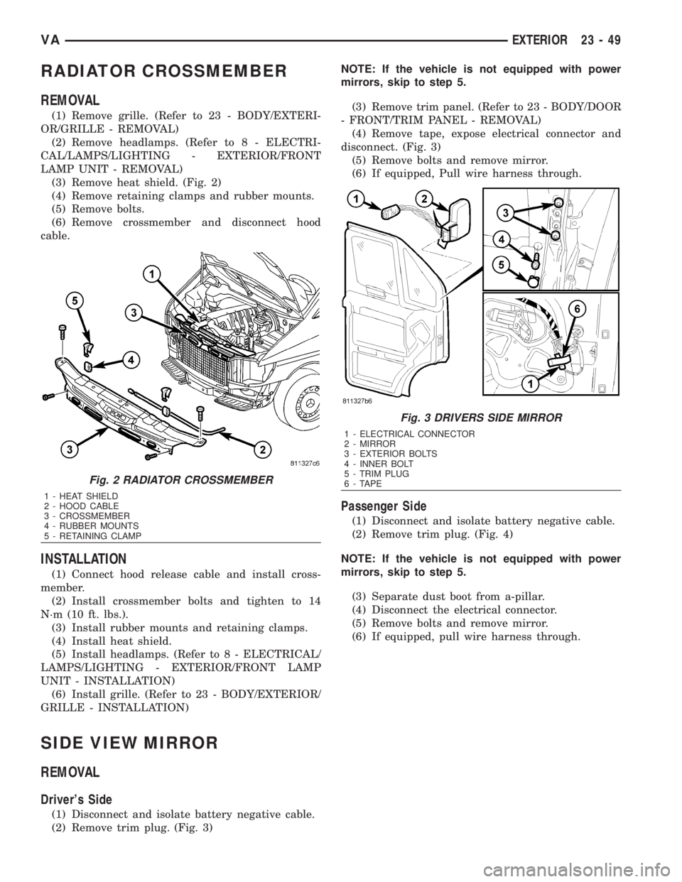
(3) Remove heat shield. (Fig. 2)
(4) Remove retaining clamps and rubber mounts.
(5) Remove bolts.
(6) Remove crossmember and disconnect hood
cable.
INSTALLATION
(1) Connect hood release cable and install cross-
member.
(2) Install crossmember bolts and tighten to 14
N´m (10 ft. lbs.).
(3) Install rubber mounts and retaining clamps.
(4) Install heat shield.
(5) Install headlamps. (Refer to 8 - ELECTRICAL/
LAMPS/LIGHTING - EXTERIOR/FRONT LAMP
UNIT - INSTALLATION)
(6) Install grille. (Refer to 23 - BODY/EXTERIOR/
GRILLE - INSTALLATION)
SIDE VIEW MIRROR
REMOVAL
Driver's Side
(1) Disconnect and isolate battery negative cable.
(2) Remove trim plug. (Fig. 3)NOTE: If the vehicle is not equipped with power
mirrors, skip to step 5.
(3) Remove trim panel. (Refer to 23 - BODY/DOOR
- FRONT/TRIM PANEL - REMOVAL)
(4) Remove tape, expose electrical connector and
disconnect. (Fig. 3)
(5) Remove bolts and remove mirror.
(6) If equipped, Pull wire harness through.
Passenger Side
(1) Disconnect and isolate battery negative cable.
(2) Remove trim plug. (Fig. 4)
NOTE: If the vehicle is not equipped with power
mirrors, skip to step 5.
(3) Separate dust boot from a-pillar.
(4) Disconnect the electrical connector.
(5) Remove bolts and remove mirror.
(6) If equipped, pull wire harness through.
Fig. 2 RADIATOR CROSSMEMBER
1 - HEAT SHIELD
2 - HOOD CABLE
3 - CROSSMEMBER
4 - RUBBER MOUNTS
5 - RETAINING CLAMP
Fig. 3 DRIVERS SIDE MIRROR
1 - ELECTRICAL CONNECTOR
2 - MIRROR
3 - EXTERIOR BOLTS
4 - INNER BOLT
5 - TRIM PLUG
6 - TAPE
VAEXTERIOR 23 - 49
Page 1994 of 2305

HOOD
TABLE OF CONTENTS
page page
HINGE
REMOVAL.............................51
INSTALLATION.........................51
HOOD
REMOVAL.............................51
INSTALLATION.........................51
ADJUSTMENTS
ADJUSTMENT........................52
LATCH
REMOVAL.............................52
INSTALLATION.........................52
LATCH RELEASE CABLE
REMOVAL.............................52INSTALLATION.........................52
LATCH RELEASE HANDLE
REMOVAL.............................52
INSTALLATION.........................52
PROP ROD
REMOVAL.............................53
INSTALLATION.........................53
SAFETY LATCH
REMOVAL.............................53
INSTALLATION.........................54
HINGE
REMOVAL
NOTE: It is not necessary to remove the hood to
replace one or both hinges. The hinges can be
replaced one at a time.
(1) Open hood and support as needed.
(2) Using a grease pencil or equivalent, mark the
position of the hinge on the hood and cowl.
(3) Remove the two hood nuts.
(4) Remove the two cowl bolts and remove hinge.
INSTALLATION
(1) Position hinge on vehicle and align reference
marks.
(2) Install cowl bolts and tighten to 23 N´m (17 ft.
lbs.).
(3) Install hood nuts and tighten to 23 N´m (17 ft.
lbs.).
(4) Check and adjust hood if necessary. (Refer to
23 - BODY/HOOD/HOOD - ADJUSTMENTS)
HOOD
REMOVAL
(1) Raise and support hood.
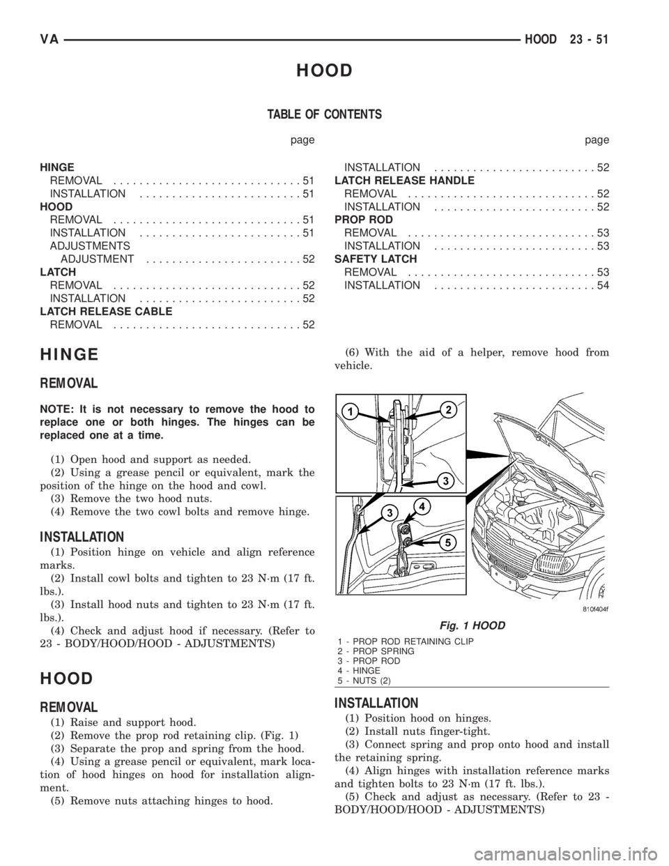
(2) Remove the prop rod retaining clip. (Fig. 1)
(3) Separate the prop and spring from the hood.
(4) Using a grease pencil or equivalent, mark loca-
tion of hood hinges on hood for installation align-
ment.
(5) Remove nuts attaching hinges to hood.(6) With the aid of a helper, remove hood from
vehicle.
INSTALLATION
(1) Position hood on hinges.
(2) Install nuts finger-tight.
(3) Connect spring and prop onto hood and install
the retaining spring.
(4) Align hinges with installation reference marks
and tighten bolts to 23 N´m (17 ft. lbs.).
(5) Check and adjust as necessary. (Refer to 23 -
BODY/HOOD/HOOD - ADJUSTMENTS)
Fig. 1 HOOD
1 - PROP ROD RETAINING CLIP
2 - PROP SPRING
3 - PROP ROD
4 - HINGE
5 - NUTS (2)
VAHOOD 23 - 51
Page 1995 of 2305

ADJUSTMENTS
ADJUSTMENT
SPECIFICATIONS
DESCRIPTION SPECIFICATION
Left and right hood gaps 5 0.5 mm
Flush offset for hood/
fender·1.0 mm
(1) Check hood to fender gap. Refer to the SPECI-
FICATIONS table.
(2) Loosen hinge to cowl bolts and adjust hood side
to side, if necessary.
(3) Tighten bolts to 23 N´m (17 ft. lbs.).
(4) Check hood to fender flushness. Refer to the
SPECIFICATIONS table.
(5) Loosen hinge to hood nuts and adjust hood up
and down, if necessary.
(6) Tighten nuts to 23 N´m (17 ft. lbs.).
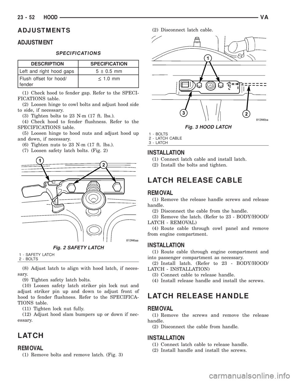
(7) Loosen safety latch bolts. (Fig. 2)
(8) Adjust latch to align with hood latch, if neces-
sary.
(9) Tighten safety latch bolts.
(10) Loosen safety latch striker pin lock nut and
adjust striker pin up and down to adjust front of
hood to fender flushness. Refer to the SPECIFICA-
TIONS table.
(11) Tighten lock nut fully.
(12) Adjust hood slam bumpers up or down if nec-
essary.
LATCH
REMOVAL
(1) Remove bolts and remove latch. (Fig. 3)(2) Disconnect latch cable.
INSTALLATION
(1) Connect latch cable and install latch.
(2) Install the bolts and tighten.
LATCH RELEASE CABLE
REMOVAL
(1) Remove the release handle screws and release
handle.
(2) Disconnect the cable from the handle.
(3) Remove the latch. (Refer to 23 - BODY/HOOD/
LATCH - REMOVAL)
(4) Route cable through cowl panel and remove
from engine compartment.
INSTALLATION
(1) Route cable through engine compartment and
into passenger compartment as necessary.
(2) Install latch. (Refer to 23 - BODY/HOOD/
LATCH - INSTALLATION)
(3) Connect cable to release handle.
(4) Install release handle and install the screws.
LATCH RELEASE HANDLE
REMOVAL
(1) Remove the screws and remove the release
handle.
(2) Disconnect the cable from handle.
INSTALLATION
(1) Connect latch cable to release handle.
(2) Install handle and install the screws.
Fig. 2 SAFETY LATCH
1 - SAFETY LATCH
2 - BOLTS
Fig. 3 HOOD LATCH
1 - BOLTS
2 - LATCH CABLE
3-LATCH
23 - 52 HOODVA