2006 MERCEDES-BENZ SPRINTER jump start
[x] Cancel search: jump startPage 159 of 2305
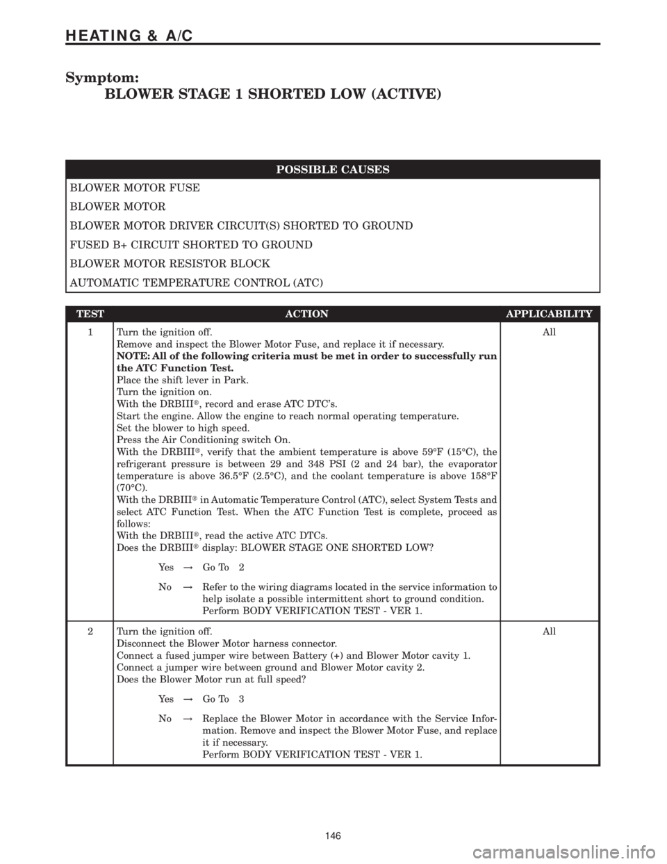
Symptom:
BLOWER STAGE 1 SHORTED LOW (ACTIVE)
POSSIBLE CAUSES
BLOWER MOTOR FUSE
BLOWER MOTOR
BLOWER MOTOR DRIVER CIRCUIT(S) SHORTED TO GROUND
FUSED B+ CIRCUIT SHORTED TO GROUND
BLOWER MOTOR RESISTOR BLOCK
AUTOMATIC TEMPERATURE CONTROL (ATC)
TEST ACTION APPLICABILITY
1 Turn the ignition off.
Remove and inspect the Blower Motor Fuse, and replace it if necessary.
NOTE: All of the following criteria must be met in order to successfully run
the ATC Function Test.
Place the shift lever in Park.
Turn the ignition on.
With the DRBIIIt, record and erase ATC DTC's.
Start the engine. Allow the engine to reach normal operating temperature.
Set the blower to high speed.
Press the Air Conditioning switch On.
With the DRBIIIt, verify that the ambient temperature is above 59ÉF (15ÉC), the
refrigerant pressure is between 29 and 348 PSI (2 and 24 bar), the evaporator
temperature is above 36.5ÉF (2.5ÉC), and the coolant temperature is above 158ÉF
(70ÉC).
With the DRBIIItin Automatic Temperature Control (ATC), select System Tests and
select ATC Function Test. When the ATC Function Test is complete, proceed as
follows:
With the DRBIIIt, read the active ATC DTCs.
Does the DRBIIItdisplay: BLOWER STAGE ONE SHORTED LOW?All
Ye s!Go To 2
No!Refer to the wiring diagrams located in the service information to
help isolate a possible intermittent short to ground condition.
Perform BODY VERIFICATION TEST - VER 1.
2 Turn the ignition off.
Disconnect the Blower Motor harness connector.
Connect a fused jumper wire between Battery (+) and Blower Motor cavity 1.
Connect a jumper wire between ground and Blower Motor cavity 2.
Does the Blower Motor run at full speed?All
Ye s!Go To 3
No!Replace the Blower Motor in accordance with the Service Infor-
mation. Remove and inspect the Blower Motor Fuse, and replace
it if necessary.
Perform BODY VERIFICATION TEST - VER 1.
146
HEATING & A/C
Page 257 of 2305

Verification Tests
ABS VERIFICATION TEST - VER 1 APPLICABILITY
1. Turn the ignition off.
2. Connect all previously disconnected components and connectors.
3. Ensure all accessories are turned off and the battery is fully charged.
4. Ensure that the Ignition is on, and with the DRBIII, erase all Diagnostic Trouble Codes from
ALL modules. Start the engine and allow it to run for 2 minutes and fully operate the system
that was malfunctioning.
5. Turn the ignition off and wait 5 seconds. Turn the ignition on and using the DRBIII, read
DTC's from ALL modules.
6. If any Diagnostic Trouble Codes are present, return to Symptom list and troubleshoot new
or recurring symptom.
7. NOTE: If the CAB/HCU was replaced, ensure the CAB has been initialized
8. NOTE: If the SKREEM or ECM was replaced, refer to the service information for
proper programming procedures.
9. NOTE: For Sensor Circuit/Signal and Pump Motor faults, the CAB must sense all 4
wheels at 12 km/h (8 mph) before it will extinguish the ABS Indicator.
10. If there are no DTC's present after turning ignition on, road test the vehicle for at least 5
minutes. Perform several antilock braking stops.
11. CAUTION: Ensure braking capability is available before road testing.
12. Again, with the DRBIIItread DTC's. If any DTC's are present, return to Symptom list.
13. If there are no Diagnostic Trouble Codes (DTC's) present, and the customer's concern can
no longer be duplicated, the repair is complete.
Are any DTC's present or is the original concern still present?All
Ye s!Repair is not complete, refer to appropriate symptom.
No!Repair is complete.
AIRBAG VERIFICATION TEST - VER 1 APPLICABILITY
1. Remove any special tools or jumper wires and reconnect all previously disconnected
components - except the Battery.
2. WARNING: TO AVOID PERSONAL INJURY OR DEATH, TURN THE IGNITION ON,
THEN RECONNECT THE BATTERY.
3. Connect the DRBIIItto the Data Link Connector - use the most current software available.
4. Use the DRBIIItand erase the stored codes in all airbag system modules.
5. Turn the ignition off, and wait 15 seconds, then turn the ignition on.
6. Wait one minute, and read active codes and if there are none present read the stored codes.
7. Note: If equipped with Airbag On - Off switch, read the DTC's in all switch positions.
8. Note: Read the DTC's in all airbag system related modules.
9. If the DRBIIItshows any active or stored codes, return to the Symptom list and follow path
specified for that trouble code. If no active or stored codes are present, the repair is complete.
Are any DTC's present or is the original condition still present?All
YES
Repair is not complete, refer to appropriate symptom list.
NO
Repair is complete.
244
VERIFICATION TESTS
Page 258 of 2305
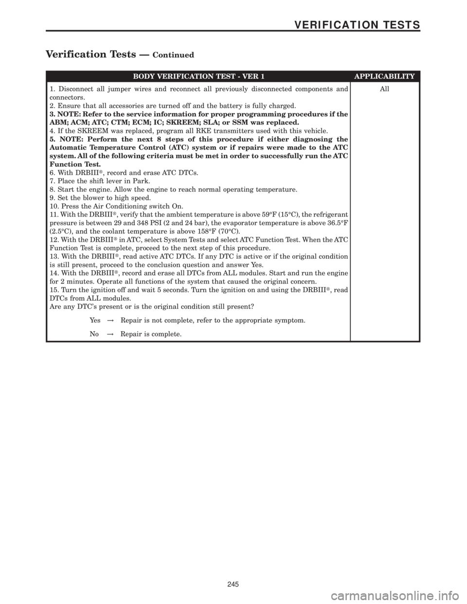
BODY VERIFICATION TEST - VER 1 APPLICABILITY
1. Disconnect all jumper wires and reconnect all previously disconnected components and
connectors.
2. Ensure that all accessories are turned off and the battery is fully charged.
3. NOTE: Refer to the service information for proper programming procedures if the
ABM; ACM; ATC; CTM; ECM; IC; SKREEM; SLA; or SSM was replaced.
4. If the SKREEM was replaced, program all RKE transmitters used with this vehicle.
5. NOTE: Perform the next 8 steps of this procedure if either diagnosing the
Automatic Temperature Control (ATC) system or if repairs were made to the ATC
system. All of the following criteria must be met in order to successfully run the ATC
Function Test.
6. With DRBIIIt, record and erase ATC DTCs.
7. Place the shift lever in Park.
8. Start the engine. Allow the engine to reach normal operating temperature.
9. Set the blower to high speed.
10. Press the Air Conditioning switch On.
11. With the DRBIIIt, verify that the ambient temperature is above 59ÉF (15ÉC), the refrigerant
pressure is between 29 and 348 PSI (2 and 24 bar), the evaporator temperature is above 36.5ÉF
(2.5ÉC), and the coolant temperature is above 158ÉF (70ÉC).
12. With the DRBIIItin ATC, select System Tests and select ATC Function Test. When the ATC
Function Test is complete, proceed to the next step of this procedure.
13. With the DRBIIIt, read active ATC DTCs. If any DTC is active or if the original condition
is still present, proceed to the conclusion question and answer Yes.
14. With the DRBIIIt, record and erase all DTCs from ALL modules. Start and run the engine
for 2 minutes. Operate all functions of the system that caused the original concern.
15. Turn the ignition off and wait 5 seconds. Turn the ignition on and using the DRBIIIt, read
DTCs from ALL modules.
Are any DTC's present or is the original condition still present?All
Ye s!Repair is not complete, refer to the appropriate symptom.
No!Repair is complete.
245
VERIFICATION TESTS
Verification Tests ÐContinued
Page 259 of 2305
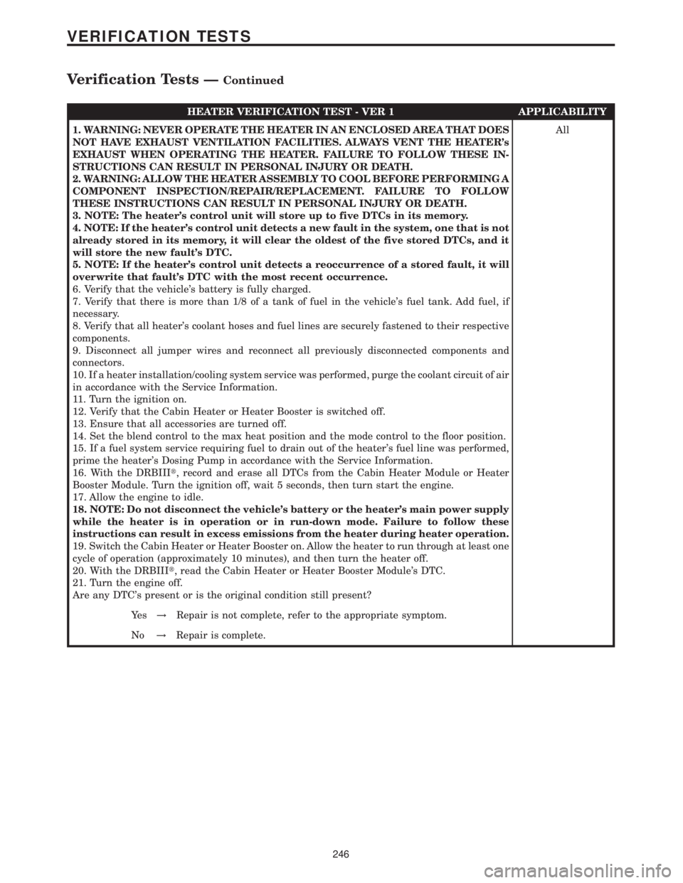
HEATER VERIFICATION TEST - VER 1 APPLICABILITY
1. WARNING: NEVER OPERATE THE HEATER IN AN ENCLOSED AREA THAT DOES
NOT HAVE EXHAUST VENTILATION FACILITIES. ALWAYS VENT THE HEATER's
EXHAUST WHEN OPERATING THE HEATER. FAILURE TO FOLLOW THESE IN-
STRUCTIONS CAN RESULT IN PERSONAL INJURY OR DEATH.
2. WARNING: ALLOW THE HEATER ASSEMBLY TO COOL BEFORE PERFORMING A
COMPONENT INSPECTION/REPAIR/REPLACEMENT. FAILURE TO FOLLOW
THESE INSTRUCTIONS CAN RESULT IN PERSONAL INJURY OR DEATH.
3. NOTE: The heater's control unit will store up to five DTCs in its memory.
4. NOTE: If the heater's control unit detects a new fault in the system, one that is not
already stored in its memory, it will clear the oldest of the five stored DTCs, and it
will store the new fault's DTC.
5. NOTE: If the heater's control unit detects a reoccurrence of a stored fault, it will
overwrite that fault's DTC with the most recent occurrence.
6. Verify that the vehicle's battery is fully charged.
7. Verify that there is more than 1/8 of a tank of fuel in the vehicle's fuel tank. Add fuel, if
necessary.
8. Verify that all heater's coolant hoses and fuel lines are securely fastened to their respective
components.
9. Disconnect all jumper wires and reconnect all previously disconnected components and
connectors.
10. If a heater installation/cooling system service was performed, purge the coolant circuit of air
in accordance with the Service Information.
11. Turn the ignition on.
12. Verify that the Cabin Heater or Heater Booster is switched off.
13. Ensure that all accessories are turned off.
14. Set the blend control to the max heat position and the mode control to the floor position.
15. If a fuel system service requiring fuel to drain out of the heater's fuel line was performed,
prime the heater's Dosing Pump in accordance with the Service Information.
16. With the DRBIIIt, record and erase all DTCs from the Cabin Heater Module or Heater
Booster Module. Turn the ignition off, wait 5 seconds, then turn start the engine.
17. Allow the engine to idle.
18. NOTE: Do not disconnect the vehicle's battery or the heater's main power supply
while the heater is in operation or in run-down mode. Failure to follow these
instructions can result in excess emissions from the heater during heater operation.
19. Switch the Cabin Heater or Heater Booster on. Allow the heater to run through at least one
cycle of operation (approximately 10 minutes), and then turn the heater off.
20. With the DRBIIIt, read the Cabin Heater or Heater Booster Module's DTC.
21. Turn the engine off.
Are any DTC's present or is the original condition still present?All
Ye s!Repair is not complete, refer to the appropriate symptom.
No!Repair is complete.
246
VERIFICATION TESTS
Verification Tests ÐContinued
Page 401 of 2305
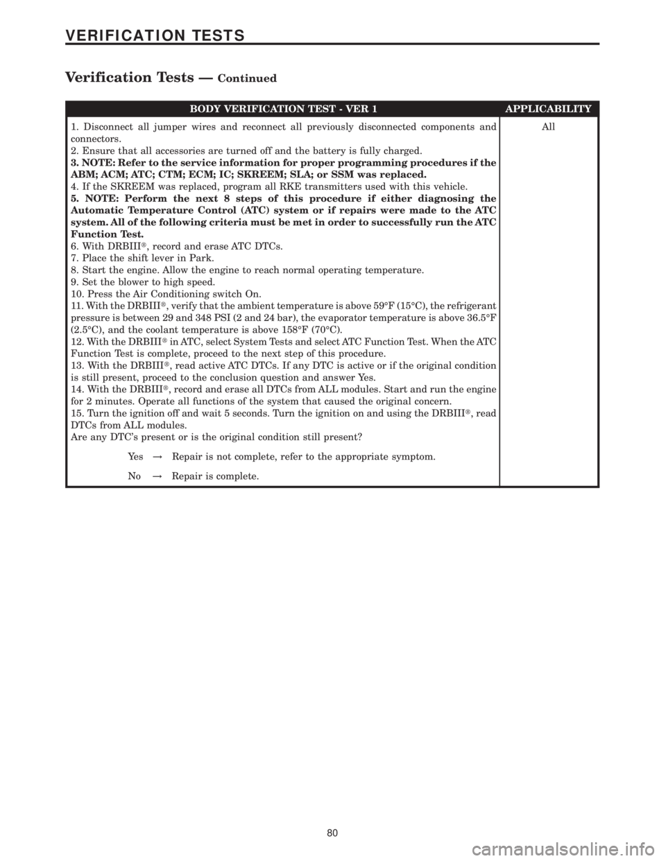
BODY VERIFICATION TEST - VER 1 APPLICABILITY
1. Disconnect all jumper wires and reconnect all previously disconnected components and
connectors.
2. Ensure that all accessories are turned off and the battery is fully charged.
3. NOTE: Refer to the service information for proper programming procedures if the
ABM; ACM; ATC; CTM; ECM; IC; SKREEM; SLA; or SSM was replaced.
4. If the SKREEM was replaced, program all RKE transmitters used with this vehicle.
5. NOTE: Perform the next 8 steps of this procedure if either diagnosing the
Automatic Temperature Control (ATC) system or if repairs were made to the ATC
system. All of the following criteria must be met in order to successfully run the ATC
Function Test.
6. With DRBIIIt, record and erase ATC DTCs.
7. Place the shift lever in Park.
8. Start the engine. Allow the engine to reach normal operating temperature.
9. Set the blower to high speed.
10. Press the Air Conditioning switch On.
11. With the DRBIIIt, verify that the ambient temperature is above 59ÉF (15ÉC), the refrigerant
pressure is between 29 and 348 PSI (2 and 24 bar), the evaporator temperature is above 36.5ÉF
(2.5ÉC), and the coolant temperature is above 158ÉF (70ÉC).
12. With the DRBIIItin ATC, select System Tests and select ATC Function Test. When the ATC
Function Test is complete, proceed to the next step of this procedure.
13. With the DRBIIIt, read active ATC DTCs. If any DTC is active or if the original condition
is still present, proceed to the conclusion question and answer Yes.
14. With the DRBIIIt, record and erase all DTCs from ALL modules. Start and run the engine
for 2 minutes. Operate all functions of the system that caused the original concern.
15. Turn the ignition off and wait 5 seconds. Turn the ignition on and using the DRBIIIt, read
DTCs from ALL modules.
Are any DTC's present or is the original condition still present?All
Ye s!Repair is not complete, refer to the appropriate symptom.
No!Repair is complete.
80
VERIFICATION TESTS
Verification Tests ÐContinued
Page 527 of 2305
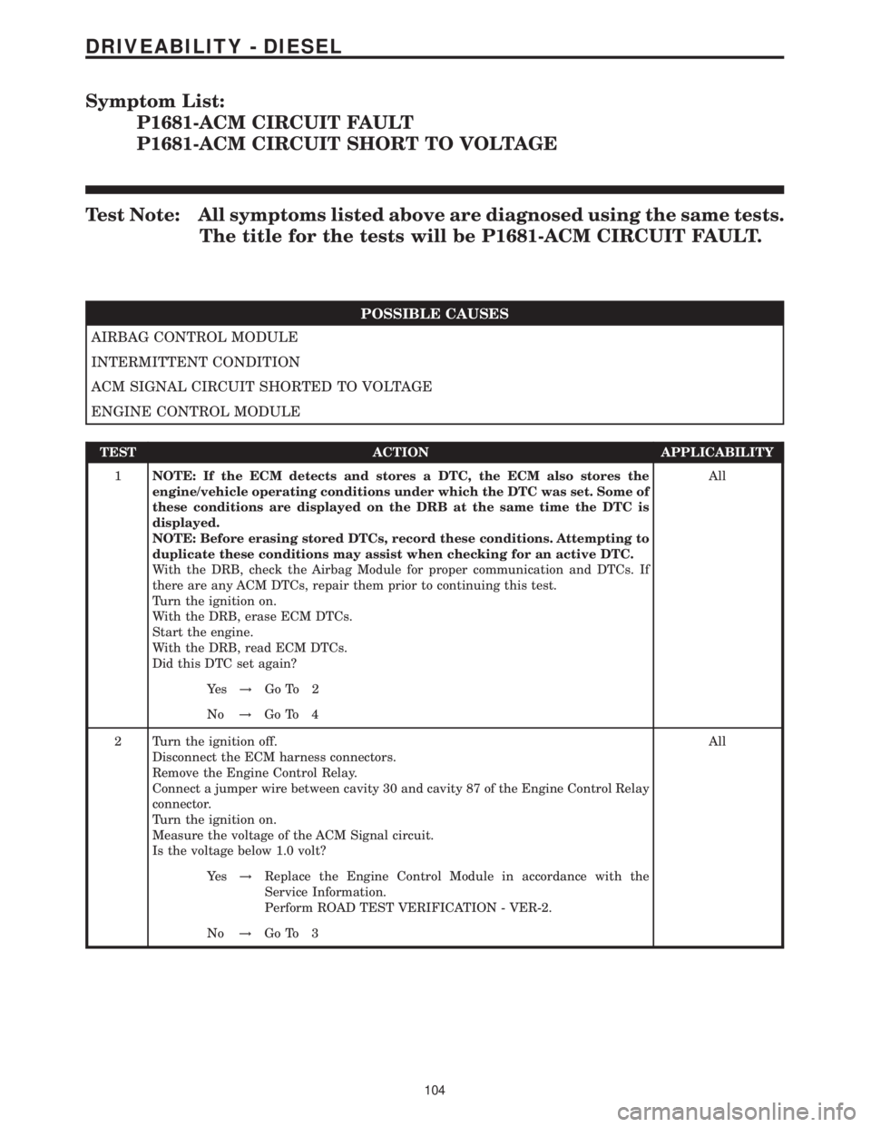
Symptom List:
P1681-ACM CIRCUIT FAULT
P1681-ACM CIRCUIT SHORT TO VOLTAGE
Test Note: All symptoms listed above are diagnosed using the same tests.
The title for the tests will be P1681-ACM CIRCUIT FAULT.
POSSIBLE CAUSES
AIRBAG CONTROL MODULE
INTERMITTENT CONDITION
ACM SIGNAL CIRCUIT SHORTED TO VOLTAGE
ENGINE CONTROL MODULE
TEST ACTION APPLICABILITY
1NOTE: If the ECM detects and stores a DTC, the ECM also stores the
engine/vehicle operating conditions under which the DTC was set. Some of
these conditions are displayed on the DRB at the same time the DTC is
displayed.
NOTE: Before erasing stored DTCs, record these conditions. Attempting to
duplicate these conditions may assist when checking for an active DTC.
With the DRB, check the Airbag Module for proper communication and DTCs. If
there are any ACM DTCs, repair them prior to continuing this test.
Turn the ignition on.
With the DRB, erase ECM DTCs.
Start the engine.
With the DRB, read ECM DTCs.
Did this DTC set again?All
Ye s!Go To 2
No!Go To 4
2 Turn the ignition off.
Disconnect the ECM harness connectors.
Remove the Engine Control Relay.
Connect a jumper wire between cavity 30 and cavity 87 of the Engine Control Relay
connector.
Turn the ignition on.
Measure the voltage of the ACM Signal circuit.
Is the voltage below 1.0 volt?All
Ye s!Replace the Engine Control Module in accordance with the
Service Information.
Perform ROAD TEST VERIFICATION - VER-2.
No!Go To 3
104
DRIVEABILITY - DIESEL
Page 571 of 2305

TEST ACTION APPLICABILITY
6 Turn the ignition off.
Disconnect the CKP Sensor harness connector.
Disconnect the ECM harness connectors.
Remove the Engine Control Relay.
Connect a jumper wire between cavity 30 and cavity 87 of the Engine Control Relay
connector.
Turn the ignition on.
Measure the voltage of both CKP Sensor Signal circuits.
Is the voltage below 1.0 volt for both measurements?All
Ye s!Go To 7
No!Repair the CKP Sensor Signal circuit(s) for a short to voltage.
Perform ROAD TEST VERIFICATION - VER-2.
7 Turn the ignition off.
Using the DRB lab scope, backprobe both of the CKP Sensor Signal circuits at the
ECM harness connector.
NOTE: Refer to Charts and Graphs to view a correct CKP Sensor signal.
Start the engine, if the engine will not start, crank the engine for several seconds
while monitoring the DRB.
Does the DRB display a steady clean CKP Signal pattern for both circuits?All
Ye s!Go To 8
No!Replace the Crankshaft Position Sensor.
Perform ROAD TEST VERIFICATION - VER-2.
8 Turn the ignition off.
Inspect the CKP Sensor Shield circuit.
Were any problems found?All
Ye s!Repair the Shield circuit as necessary.
Perform ROAD TEST VERIFICATION - VER-2.
No!Go To 9
9 Turn the ignition off.
Inspect the CKP Sensor for signs of damage or improper/loose attachment to the
engine.
Inspect the flywheel for excessive dirt contamination or tooth damage which can
cause improper CKP Sensor signal output.
Where any of these problems found?All
Ye s!Repair or replace as necessary.
Perform ROAD TEST VERIFICATION - VER-2.
No!Replace and program the Engine Control Module in accordance
with the Service Information.
Perform ROAD TEST VERIFICATION - VER-2.
148
DRIVEABILITY - DIESEL
P2045-CRANKSHAFT POSITION SENSOR CIRCUIT LOST SIGNAL Ð
Continued
Page 585 of 2305
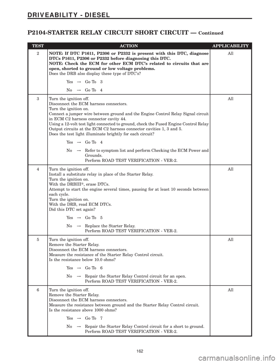
TEST ACTION APPLICABILITY
2NOTE: If DTC P1611, P2306 or P2332 is present with this DTC, diagnose
DTCs P1611, P2306 or P2332 before diagnosing this DTC.
NOTE: Check the ECM for other ECM DTC's related to circuits that are
open, shorted to ground or low voltage problems.
Does the DRB also display these type of DTC's?All
Ye s!Go To 3
No!Go To 4
3 Turn the ignition off.
Disconnect the ECM harness connectors.
Turn the ignition on.
Connect a jumper wire between ground and the Engine Control Relay Signal circuit
in ECM C2 harness connector cavity 44.
Using a 12-volt test light connected to ground, check the Fused Engine Control Relay
Output circuits at the ECM C2 harness connector cavities 1, 3 and 5.
Does the test light illuminate brightly for each circuit?All
Ye s!Go To 4
No!Refer to symptom list and perform Checking the ECM Power and
Grounds.
Perform ROAD TEST VERIFICATION - VER-2.
4 Turn the ignition off.
Install a substitute relay in place of the Starter Relay.
Turn the ignition on.
With the DRBIIIt, erase DTCs.
Attempt to start the engine several times, pausing for at least 10 seconds between
each cycle.
Turn the ignition on.
With the DRB, read ECM DTCs.
Did this DTC set again?All
Ye s!Go To 5
No!Replace the Starter Relay.
Perform ROAD TEST VERIFICATION - VER-2.
5 Turn the ignition off.
Remove the Starter Relay.
Disconnect the ECM harness connectors.
Measure the resistance of the Starter Relay Control circuit.
Is the resistance below 10.0 ohms?All
Ye s!Go To 6
No!Repair the Starter Relay Control circuit for an open.
Perform ROAD TEST VERIFICATION - VER-2.
6 Turn the ignition off.
Remove the Starter Relay.
Disconnect the ECM harness connectors.
Measure the resistance between ground and the Starter Relay Control circuit.
Is the resistance above 1000 ohms?All
Ye s!Go To 7
No!Repair the Starter Relay Control circuit for a short to ground.
Perform ROAD TEST VERIFICATION - VER-2.
162
DRIVEABILITY - DIESEL
P2104-STARTER RELAY CIRCUIT SHORT CIRCUIT ÐContinued