2006 MERCEDES-BENZ SPRINTER jump start
[x] Cancel search: jump startPage 867 of 2305

For battery system maintenance schedules and
jump starting procedures, see the owner's manual in
the vehicle glove box. Optionally, refer to the Lubri-
cation and Maintenance section of this manual for
the recommended battery maintenance schedules and
for the proper battery jump starting procedure. While
battery charging can be considered a maintenance
procedure, the battery charging procedure and
related information are located later in this section of
this service manual. This was done because the bat-
tery must be fully-charged before any battery system
diagnosis or testing procedures can be performed.
OPERATION
The battery system is designed to provide a safe,
efficient, reliable and mobile means of delivering and
storing electrical energy. This electrical energy is
required to operate the engine starting system, as
well as to operate many of the other vehicle acces-
sory systems for limited durations while the engine
and/or the charging system are not operating. The
battery system is also designed to provide a reserve
of electrical energy to supplement the charging sys-
tem for short durations while the engine is running
and the electrical current demands of the vehicle
exceed the output of the charging system. In addition
to delivering, and storing electrical energy for the
vehicle, the battery system serves as a capacitor and
voltage stabilizer for the vehicle electrical system. It
absorbs most abnormal or transient voltages caused
by the switching of any of the electrical components
or circuits in the vehicle.
DIAGNOSIS AND TESTING - BATTERY SYSTEM
The battery, starting, and charging systems in the
vehicle operate with one another and must be tested
as a complete system. In order for the engine to start
and the battery to maintain its charge properly, all ofthe components that are used in these systems must
perform within specifications. It is important that
the battery, starting, and charging systems be thor-
oughly tested and inspected any time a battery needs
to be charged or replaced. The cause of abnormal bat-
tery discharge, overcharging or early battery failure
must be diagnosed and corrected before a battery is
replaced and before a vehicle is returned to service.
The service information for these systems has been
separated within this service manual to make it eas-
ier to locate the specific information you are seeking.
However, when attempting to diagnose any of these
systems, it is important that you keep their interde-
pendency in mind.
The diagnostic procedures used for the battery,
starting, and charging systems include the most
basic conventional diagnostic methods, to the more
sophisticated On-Board Diagnostics (OBD) built into
the Powertrain Control Module (PCM). Use of an
induction-type milliampere ammeter, a volt/ohmme-
ter, a battery charger, a carbon pile rheostat (load
tester) and a 12-volt test lamp may be required. All
OBD-sensed systems are monitored by the PCM.
Each monitored circuit is assigned a Diagnostic Trou-
ble Code (DTC). The PCM will store a DTC in elec-
tronic memory for any failure it detects. Refer to
Charging System for the proper charging system on-
board diagnostic test procedures.
MICRO 420 BATTERY TESTER
The Micro 420 automotive battery tester is
designed to help the dealership technicians diagnose
the cause of a defective battery. Follow the instruc-
tion manual supplied with the tester to properly
diagnose a vehicle. If the instruction manual is not
available refer to the standard procedure in this sec-
tion, which includes the directions for using the
Micro 420 battery tester.
8F - 2 BATTERY SYSTEMVA
Page 898 of 2305
SPECIFICATIONS
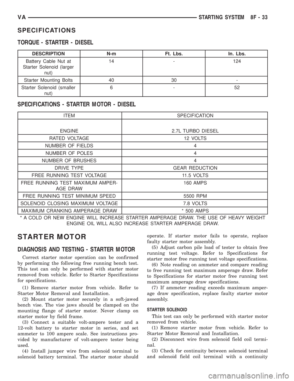
TORQUE - STARTER - DIESEL
DESCRIPTION N-m Ft. Lbs. In. Lbs.
Battery Cable Nut at
Starter Solenoid (larger
nut)14 - 124
Starter Mounting Bolts 40 30 -
Starter Solenoid (smaller
nut)6-52
SPECIFICATIONS - STARTER MOTOR - DIESEL
ITEM SPECIFICATION
ENGINE 2.7L TURBO DIESEL
RATED VOLTAGE 12 VOLTS
NUMBER OF FIELDS 4
NUMBER OF POLES 4
NUMBER OF BRUSHES 4
DRIVE TYPE GEAR REDUCTION
FREE RUNNING TEST VOLTAGE 11.5 VOLTS
FREE RUNNING TEST MAXIMUM AMPER-
AGE DRAW160 AMPS
FREE RUNNING TEST MINIMUM SPEED 5500 RPM
SOLENOID CLOSING MAXIMUM VOLTAGE 7.8 VOLTS
MAXIMUM CRANKING AMPERAGE DRAW * 500 AMPS
* A COLD OR NEW ENGINE WILL INCREASE STARTER AMPERAGE DRAW. THE USE OF HEAVY WEIGHT
ENGINE OIL WILL ALSO INCREASE STARTER AMPERAGE DRAW.
STARTER MOTOR
DIAGNOSIS AND TESTING - STARTER MOTOR
Correct starter motor operation can be confirmed
by performing the following free running bench test.
This test can only be performed with starter motor
removed from vehicle. Refer to Starter Specifications
for specifications.
(1) Remove starter motor from vehicle. Refer to
Starter Motor Removal and Installation.
(2) Mount starter motor securely in a soft-jawed
bench vise. The vise jaws should be clamped on the
mounting flange of starter motor. Never clamp on
starter motor by field frame.
(3) Connect a suitable volt-ampere tester and a
12-volt battery to starter motor in series, and set
ammeter to 100 ampere scale. See instructions pro-
vided by manufacturer of volt-ampere tester being
used.
(4) Install jumper wire from solenoid terminal to
solenoid battery terminal. The starter motor shouldoperate. If starter motor fails to operate, replace
faulty starter motor assembly.
(5) Adjust carbon pile load of tester to obtain free
running test voltage. Refer to Specifications for
starter motor free running test voltage specifications.
(6) Note reading on ammeter and compare reading
to free running test maximum amperage draw. Refer
to Specifications for starter motor free running test
maximum amperage draw specifications.
(7) If ammeter reading exceeds maximum amper-
age draw specification, replace faulty starter motor
assembly.
STARTER SOLENOID
This test can only be performed with starter motor
removed from vehicle.
(1) Remove starter motor from vehicle. Refer to
Starter Motor Removal and Installation.
(2) Disconnect wire from solenoid field coil termi-
nal.
(3) Check for continuity between solenoid terminal
and solenoid field coil terminal with a continuity
VASTARTING SYSTEM 8F - 33
Page 1086 of 2305
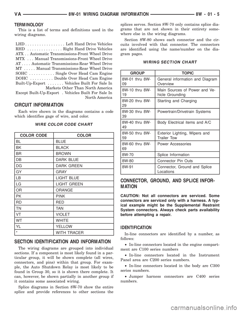
TERMINOLOGY
This is a list of terms and definitions used in the
wiring diagrams.
LHD.................Left Hand Drive Vehicles
RHD ...............Right Hand Drive Vehicles
ATX . . Automatic Transmissions-Front Wheel Drive
MTX . . . Manual Transmissions-Front Wheel Drive
AT....Automatic Transmissions-Rear Wheel Drive
MT .....Manual Transmissions-Rear Wheel Drive
SOHC...........Single Over Head Cam Engine
DOHC..........Double Over Head Cam Engine
Built-Up-Export....... Vehicles Built For Sale In
Markets Other Than North America
Except Built-Up-Export . Vehicles Built For Sale In
North America
CIRCUIT INFORMATION
Each wire shown in the diagrams contains a code
which identifies gage of wire, and color.
WIRE COLOR CODE CHART
COLOR CODE COLOR
BL BLUE
BK BLACK
BR BROWN
DB DARK BLUE
DG DARK GREEN
GY GRAY
LB LIGHT BLUE
LG LIGHT GREEN
OR ORANGE
PK PINK
RD RED
TN TAN
VT VIOLET
WT WHITE
YL YELLOW
* WITH TRACER
SECTION IDENTIFICATION AND INFORMATION
The wiring diagrams are grouped into individual
sections. If a component is most likely found in a par-
ticular group, it will be shown complete (all wires,
connectors, and pins) within that group. For exam-
ple, the Auto Shutdown Relay is most likely to be
found in Group 30, so it is shown there complete. It
can, however, be shown partially in another group if
it contains some associated wiring.
Splice diagrams in Section 8W-70 show the entire
splice and provide references to other sections thesplices serves. Section 8W-70 only contains splice dia-
grams that are not shown in their entirety some-
where else in the wiring diagrams.
Section 8W-80 shows each connector and the cir-
cuits involved with that connector. The connectors
are identified using the name/number on the dia-
gram pages.
WIRING SECTION CHART
GROUP TOPIC
8W-01 thru 8W-
09General information and Diagram
Overview
8W-10 thru 8W-
19Main Sources of Power and Ve-
hicle Grounding
8W-20 thru 8W-
29Starting and Charging
8W-30 thru 8W-
39Powertrain/Drivetrain Systems
8W-40 thru 8W-
49Body Electrical items and A/C
8W-50 thru 8W-
59Exterior Lighting, Wipers and
Trailer Tow
8W-60 thru 8W-
69Power Accessories
8W-70 Splice Information
8W-80 Connector Pin Outs
8W-91 Connector, Ground and Splice
Locations
CONNECTOR, GROUND, AND SPLICE INFOR-
MATION
CAUTION: Not all connectors are serviced. Some
connectors are serviced only with a harness. A typ-
ical example might be the Supplemental Restraint
System connectors. Always check parts availability
before attempting a repair.
IDENTIFICATION
In-line connectors are identified by a number, as
follows:
²In-line connectors located in the engine compart-
ment are C100 series numbers
²In-line connectors located in the Instrument
Panel area are C200 series numbers.
²In-line connectors located in the body are C300
series numbers.
²Jumper harness connectors are C400 series
numbers.
VA8W-01 WIRING DIAGRAM INFORMATION 8W - 01 - 5
Page 2159 of 2305
INSIDE HANDLE ACTUATOR......23-33, 23-36
INSTRUMENT CLUSTER................8J-2
INSTRUMENT PANEL ANTENNA CABLE....8A-2
INSTRUMENT PANEL ASSEMBLY........23-59
INSTRUMENT PANEL CENTER BEZEL.....23-57
INSTRUMENT PANEL DUCTS...........24-51
INTAKE AIR PRESSURE SENSOR........14-43
INTAKE AIR TEMPERATURE SENSOR.....14-42
INTAKE MANIFOLD....................9-65
INTERIOR..........................23-70
INTERMEDIATE SHAFT.................19-4
INTERNATIONAL SYMBOLS...............0-9
INTERNATIONAL SYMBOLS...........Intro.-2
INTRUSION SENSOR...................8Q-1
IN - CAR TEMPERATURE SENSOR.......24-21
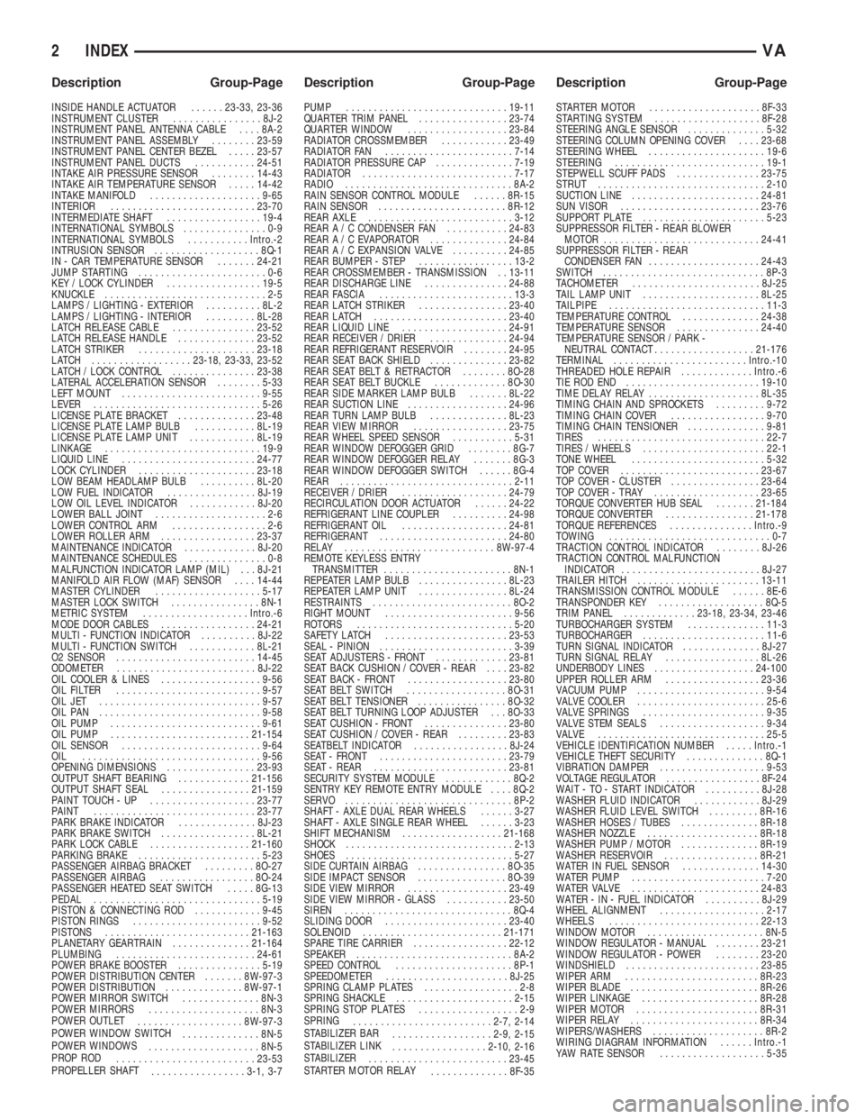
JUMP STARTING.......................0-6
KEY / LOCK CYLINDER.................19-5
KNUCKLE.............................2-5
LAMPS / LIGHTING - EXTERIOR..........8L-2
LAMPS / LIGHTING - INTERIOR.........8L-28
LATCH RELEASE CABLE...............23-52
LATCH RELEASE HANDLE..............23-52
LATCH STRIKER.....................23-18
LATCH ..................23-18, 23-33, 23-52
LATCH / LOCK CONTROL...............23-38
LATERAL ACCELERATION SENSOR........5-33
LEFT MOUNT.........................9-55
LEVER..............................5-26
LICENSE PLATE BRACKET..............23-48
LICENSE PLATE LAMP BULB...........8L-19
LICENSE PLATE LAMP UNIT............8L-19
LINKAGE............................19-9
LIQUID LINE........................24-77
LOCK CYLINDER.....................23-18
LOW BEAM HEADLAMP BULB..........8L-20
LOW FUEL INDICATOR................8J-19
LOW OIL LEVEL INDICATOR............8J-20
LOWER BALL JOINT....................2-6
LOWER CONTROL ARM.................2-6
LOWER ROLLER ARM.................23-37
MAINTENANCE INDICATOR.............8J-20
MAINTENANCE SCHEDULES..............0-8
MALFUNCTION INDICATOR LAMP (MIL) . . . 8J-21
MANIFOLD AIR FLOW (MAF) SENSOR....14-44
MASTER CYLINDER...................5-17
MASTER LOCK SWITCH................8N-1
METRIC SYSTEM...................Intro.-6
MODE DOOR CABLES.................24-21
MULTI - FUNCTION INDICATOR..........8J-22
MULTI - FUNCTION SWITCH............8L-21
O2 SENSOR.........................14-45
ODOMETER.........................8J-22
OIL COOLER & LINES..................9-56
OIL FILTER ..........................9-57
OIL JET .............................9-57
OIL PAN .............................9-58
OIL PUMP...........................9-61
OIL PUMP.........................21-154
OIL SENSOR.........................9-64
OIL ................................9-56
OPENING DIMENSIONS................23-93
OUTPUT SHAFT BEARING.............21-156
OUTPUT SHAFT SEAL................21-159
PAINT TOUCH - UP...................23-77
PAINT.............................23-77
PARK BRAKE INDICATOR..............8J-23
PARK BRAKE SWITCH.................8L-21
PARK LOCK CABLE..................21-160
PARKING BRAKE......................5-23
PASSENGER AIRBAG BRACKET.........8O-27
PASSENGER AIRBAG.................8O-24
PASSENGER HEATED SEAT SWITCH.....8G-13
PEDAL..............................5-19
PISTON & CONNECTING ROD............9-45
PISTON RINGS.......................9-52
PISTONS..........................21-163
PLANETARY GEARTRAIN..............21-164
PLUMBING.........................24-61
POWER BRAKE BOOSTER...............5-19
POWER DISTRIBUTION CENTER.......8W-97-3
POWER DISTRIBUTION..............8W-97-1
POWER MIRROR SWITCH..............8N-3
POWER MIRRORS....................8N-3
POWER OUTLET
...................8W-97-3
POWER WINDOW SWITCH
..............8N-5
POWER WINDOWS
....................8N-5
PROP ROD
.........................23-53
PROPELLER SHAFT
.................3-1, 3-7PUMP.............................19-11
QUARTER TRIM PANEL................23-74
QUARTER WINDOW..................23-84
RADIATOR CROSSMEMBER............23-49
RADIATOR FAN.......................7-14
RADIATOR PRESSURE CAP..............7-19
RADIATOR...........................7-17
RADIO..............................8A-2
RAIN SENSOR CONTROL MODULE......8R-15
RAIN SENSOR.......................8R-12
REAR AXLE..........................3-12
REAR A / C CONDENSER FAN...........24-83
REAR A / C EVAPORATOR..............24-84
REAR A / C EXPANSION VALVE..........24-85
REAR BUMPER - STEP.................13-2
REAR CROSSMEMBER - TRANSMISSION . . 13-11
REAR DISCHARGE LINE...............24-88
REAR FASCIA........................13-3
REAR LATCH STRIKER................23-40
REAR LATCH........................23-40
REAR LIQUID LINE...................24-91
REAR RECEIVER / DRIER..............24-94
REAR REFRIGERANT RESERVOIR........24-95
REAR SEAT BACK SHIELD..............23-82
REAR SEAT BELT & RETRACTOR........8O-28
REAR SEAT BELT BUCKLE.............8O-30
REAR SIDE MARKER LAMP BULB.......8L-22
REAR SUCTION LINE..................24-96
REAR TURN LAMP BULB..............8L-23
REAR VIEW MIRROR.................23-75
REAR WHEEL SPEED SENSOR...........5-31
REAR WINDOW DEFOGGER GRID........8G-7
REAR WINDOW DEFOGGER RELAY.......8G-3
REAR WINDOW DEFOGGER SWITCH......8G-4
REAR...............................2-11
RECEIVER / DRIER...................24-79
RECIRCULATION DOOR ACTUATOR......24-22
REFRIGERANT LINE COUPLER..........24-98
REFRIGERANT OIL...................24-81
REFRIGERANT.......................24-80
RELAY...........................8W-97-4
REMOTE KEYLESS ENTRY
TRANSMITTER.......................8N-1
REPEATER LAMP BULB................8L-23
REPEATER LAMP UNIT................8L-24
RESTRAINTS.........................8O-2
RIGHT MOUNT.......................9-56
ROTORS............................5-20
SAFETY LATCH......................23-53
SEAL - PINION........................3-39
SEAT ADJUSTERS - FRONT.............23-81
SEAT BACK CUSHION / COVER - REAR....23-82
SEAT BACK - FRONT..................23-80
SEAT BELT SWITCH..................8O-31
SEAT BELT TENSIONER................8O-32
SEAT BELT TURNING LOOP ADJUSTER . . . 8O-33
SEAT CUSHION - FRONT...............23-80
SEAT CUSHION / COVER - REAR.........23-83
SEATBELT INDICATOR.................8J-24
SEAT - FRONT.......................23-79
SEAT - REAR........................23-81
SECURITY SYSTEM MODULE............8Q-2
SENTRY KEY REMOTE ENTRY MODULE....8Q-2
SERVO..............................8P-2
SHAFT - AXLE DUAL REAR WHEELS......3-27
SHAFT - AXLE SINGLE REAR WHEEL......3-23
SHIFT MECHANISM..................21-168
SHOCK..............................2-13
SHOES..............................5-27
SIDE CURTAIN AIRBAG................8O-35
SIDE IMPACT SENSOR................8O-39
SIDE VIEW MIRROR..................23-49
SIDE VIEW MIRROR - GLASS...........23-50
SIREN..............................8Q-4
SLIDING DOOR......................23-40
SOLENOID.........................21-171
SPARE TIRE CARRIER.................22-12
SPEAKER............................8A-2
SPEED CONTROL.....................8P-1
SPEEDOMETER......................8J-25
SPRING CLAMP PLATES.................2-8
SPRING SHACKLE.....................2-15
SPRING STOP PLATES..................2-9
SPRING
.........................2-7, 2-14
STABILIZER BAR
..................2-9, 2-15
STABILIZER LINK
.................2-10, 2-16
STABILIZER
.........................23-45
STARTER MOTOR RELAY
..............8F-35STARTER MOTOR....................8F-33
STARTING SYSTEM...................8F-28
STEERING ANGLE SENSOR..............5-32
STEERING COLUMN OPENING COVER....23-68
STEERING WHEEL.....................19-6
STEERING...........................19-1
STEPWELL SCUFF PADS...............23-75
STRUT..............................2-10
SUCTION LINE.......................24-81
SUN VISOR.........................23-76
SUPPORT PLATE......................5-23
SUPPRESSOR FILTER - REAR BLOWER
MOTOR............................24-41
SUPPRESSOR FILTER - REAR
CONDENSER FAN....................24-43
SWITCH.............................8P-3
TACHOMETER.......................8J-25
TAIL LAMP UNIT.....................8L-25
TAILPIPE............................11-3
TEMPERATURE CONTROL..............24-38
TEMPERATURE SENSOR...............24-40
TEMPERATURE SENSOR / PARK -
NEUTRAL CONTACT..................21-176
TERMINAL........................Intro.-10
THREADED HOLE REPAIR.............Intro.-6
TIE ROD END ........................19-10
TIME DELAY RELAY....................8L-35
TIMING CHAIN AND SPROCKETS.........9-72
TIMING CHAIN COVER.................9-70
TIMING CHAIN TENSIONER..............9-81
TIRES..............................22-7
TIRES / WHEELS......................22-1
TONE WHEEL........................5-32
TOP COVER.........................23-67
TOP COVER - CLUSTER................23-64
TOP COVER - TRAY...................23-65
TORQUE CONVERTER HUB SEAL.......21-184
TORQUE CONVERTER................21-178
TORQUE REFERENCES...............Intro.-9
TOWING.............................0-7
TRACTION CONTROL INDICATOR........8J-26
TRACTION CONTROL MALFUNCTION
INDICATOR.........................8J-27
TRAILER HITCH......................13-11
TRANSMISSION CONTROL MODULE......8E-6
TRANSPONDER KEY...................8Q-5
TRIM PANEL.............23-18, 23-34, 23-46
TURBOCHARGER SYSTEM..............11-3
TURBOCHARGER......................11-6
TURN SIGNAL INDICATOR..............8J-27
TURN SIGNAL RELAY.................8L-26
UNDERBODY LINES..................24-100
UPPER ROLLER ARM.................23-36
VACUUM PUMP.......................9-54
VALVE COOLER.......................25-6
VALVE SPRINGS......................9-35
VALVE STEM SEALS...................9-34
VALVE ..............................25-5
VEHICLE IDENTIFICATION NUMBER.....Intro.-1
VEHICLE THEFT SECURITY..............8Q-1
VIBRATION DAMPER...................9-53
VOLTAGE REGULATOR.................8F-24
WAIT - TO - START INDICATOR..........8J-28
WASHER FLUID INDICATOR............8J-29
WASHER FLUID LEVEL SWITCH.........8R-16
WASHER HOSES / TUBES..............8R-18
WASHER NOZZLE....................8R-18
WASHER PUMP / MOTOR..............8R-19
WASHER RESERVOIR.................8R-21
WATER IN FUEL SENSOR..............14-30
WATER PUMP........................7-20
WATER VALVE .......................24-83
WATER - IN - FUEL INDICATOR..........8J-29
WHEEL ALIGNMENT...................2-17
WHEELS...........................22-13
WINDOW MOTOR.....................8N-5
WINDOW REGULATOR - MANUAL........23-21
WINDOW REGULATOR - POWER........23-20
WINDSHIELD........................23-85
WIPER ARM........................8R-23
WIPER BLADE.......................8R-26
WIPER LINKAGE.....................8R-28
WIPER MOTOR......................8R-31
WIPER RELAY.......................8R-34
WIPERS/WASHERS....................8R-2
WIRING DIAGRAM INFORMATION......Intro.-1
YAW RATE SENSOR...................5-35
2 INDEXVA
Description Group-Page Description Group-Page Description Group-Page
Page 2173 of 2305
5.0 REQUIRED TOOLS AND
EQUIPMENT
> DRBIIIt(diagnostic read-out box) - DRBIIIt
must use the latest release level.
> Jumper wires
> Test Light
> Ohmmeter
> Voltmeter
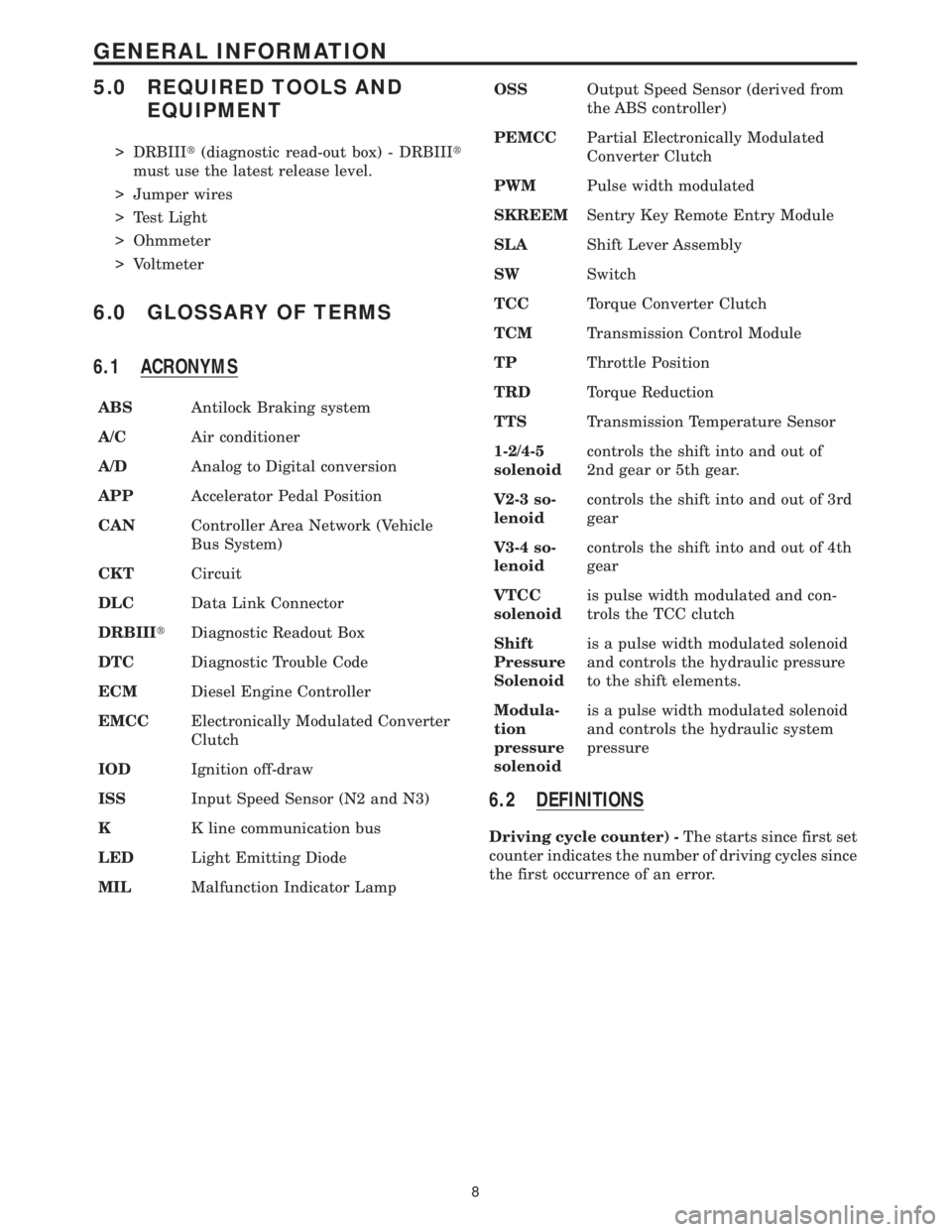
6.0 GLOSSARY OF TERMS
6.1 ACRONYMS
ABSAntilock Braking system
A/CAir conditioner
A/DAnalog to Digital conversion
APPAccelerator Pedal Position
CANController Area Network (Vehicle
Bus System)
CKTCircuit
DLCData Link Connector
DRBIIItDiagnostic Readout Box
DTCDiagnostic Trouble Code
ECMDiesel Engine Controller
EMCCElectronically Modulated Converter
Clutch
IODIgnition off-draw
ISSInput Speed Sensor (N2 and N3)
KK line communication bus
LEDLight Emitting Diode
MILMalfunction Indicator LampOSSOutput Speed Sensor (derived from
the ABS controller)
PEMCCPartial Electronically Modulated
Converter Clutch
PWMPulse width modulated
SKREEMSentry Key Remote Entry Module
SLAShift Lever Assembly
SWSwitch
TCCTorque Converter Clutch
TCMTransmission Control Module
TPThrottle Position
TRDTorque Reduction
TTSTransmission Temperature Sensor
1-2/4-5
solenoidcontrols the shift into and out of
2nd gear or 5th gear.
V2-3 so-
lenoidcontrols the shift into and out of 3rd
gear
V3-4 so-
lenoidcontrols the shift into and out of 4th
gear
VTCC
solenoidis pulse width modulated and con-
trols the TCC clutch
Shift
Pressure
Solenoidis a pulse width modulated solenoid
and controls the hydraulic pressure
to the shift elements.
Modula-
tion
pressure
solenoidis a pulse width modulated solenoid
and controls the hydraulic system
pressure
6.2 DEFINITIONS
Driving cycle counter) -The starts since first set
counter indicates the number of driving cycles since
the first occurrence of an error.
8
GENERAL INFORMATION
Page 2180 of 2305
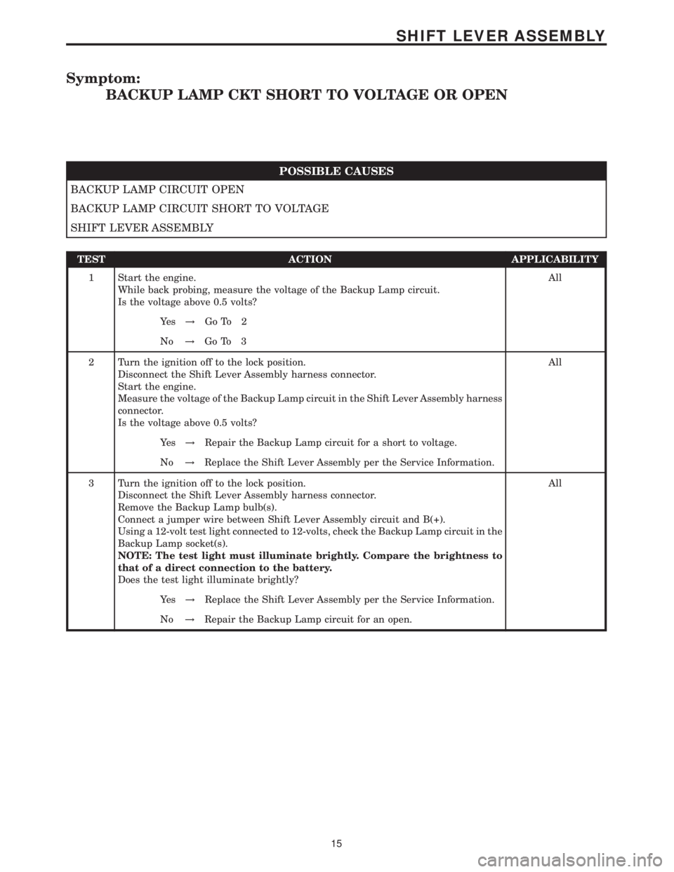
Symptom:
BACKUP LAMP CKT SHORT TO VOLTAGE OR OPEN
POSSIBLE CAUSES
BACKUP LAMP CIRCUIT OPEN
BACKUP LAMP CIRCUIT SHORT TO VOLTAGE
SHIFT LEVER ASSEMBLY
TEST ACTION APPLICABILITY
1 Start the engine.
While back probing, measure the voltage of the Backup Lamp circuit.
Is the voltage above 0.5 volts?All
Ye s!Go To 2
No!Go To 3
2 Turn the ignition off to the lock position.
Disconnect the Shift Lever Assembly harness connector.
Start the engine.
Measure the voltage of the Backup Lamp circuit in the Shift Lever Assembly harness
connector.
Is the voltage above 0.5 volts?All
Ye s!Repair the Backup Lamp circuit for a short to voltage.
No!Replace the Shift Lever Assembly per the Service Information.
3 Turn the ignition off to the lock position.
Disconnect the Shift Lever Assembly harness connector.
Remove the Backup Lamp bulb(s).
Connect a jumper wire between Shift Lever Assembly circuit and B(+).
Using a 12-volt test light connected to 12-volts, check the Backup Lamp circuit in the
Backup Lamp socket(s).
NOTE: The test light must illuminate brightly. Compare the brightness to
that of a direct connection to the battery.
Does the test light illuminate brightly?All
Ye s!Replace the Shift Lever Assembly per the Service Information.
No!Repair the Backup Lamp circuit for an open.
15
SHIFT LEVER ASSEMBLY
Page 2272 of 2305
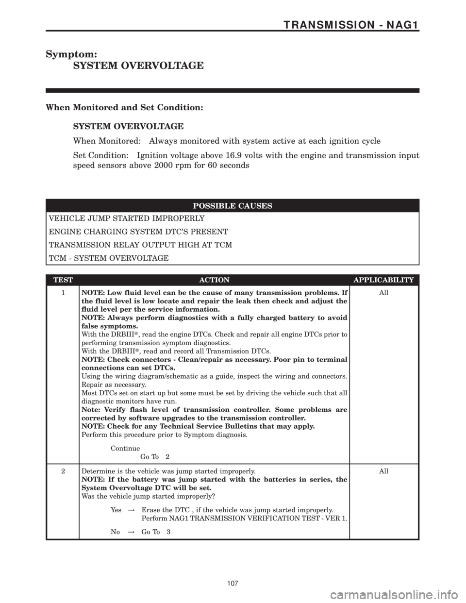
Symptom:
SYSTEM OVERVOLTAGE
When Monitored and Set Condition:
SYSTEM OVERVOLTAGE
When Monitored: Always monitored with system active at each ignition cycle
Set Condition: Ignition voltage above 16.9 volts with the engine and transmission input
speed sensors above 2000 rpm for 60 seconds
POSSIBLE CAUSES
VEHICLE JUMP STARTED IMPROPERLY
ENGINE CHARGING SYSTEM DTC'S PRESENT
TRANSMISSION RELAY OUTPUT HIGH AT TCM
TCM - SYSTEM OVERVOLTAGE
TEST ACTION APPLICABILITY
1NOTE: Low fluid level can be the cause of many transmission problems. If
the fluid level is low locate and repair the leak then check and adjust the
fluid level per the service information.
NOTE: Always perform diagnostics with a fully charged battery to avoid
false symptoms.
With the DRBIIIt, read the engine DTCs. Check and repair all engine DTCs prior to
performing transmission symptom diagnostics.
With the DRBIIIt, read and record all Transmission DTCs.
NOTE: Check connectors - Clean/repair as necessary. Poor pin to terminal
connections can set DTCs.
Using the wiring diagram/schematic as a guide, inspect the wiring and connectors.
Repair as necessary.
Most DTCs set on start up but some must be set by driving the vehicle such that all
diagnostic monitors have run.
Note: Verify flash level of transmission controller. Some problems are
corrected by software upgrades to the transmission controller.
NOTE: Check for any Technical Service Bulletins that may apply.
Perform this procedure prior to Symptom diagnosis.All
Continue
Go To 2
2 Determine is the vehicle was jump started improperly.
NOTE: If the battery was jump started with the batteries in series, the
System Overvoltage DTC will be set.
Was the vehicle jump started improperly?All
Ye s!Erase the DTC , if the vehicle was jump started improperly.
Perform NAG1 TRANSMISSION VERIFICATION TEST - VER 1.
No!Go To 3
107
TRANSMISSION - NAG1