2006 MERCEDES-BENZ SPRINTER jump start
[x] Cancel search: jump startPage 586 of 2305
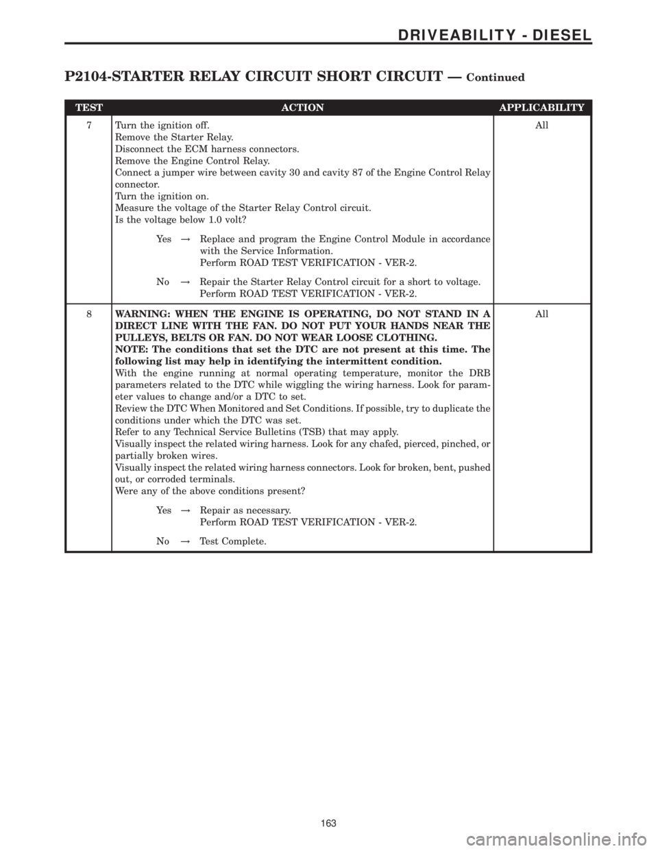
TEST ACTION APPLICABILITY
7 Turn the ignition off.
Remove the Starter Relay.
Disconnect the ECM harness connectors.
Remove the Engine Control Relay.
Connect a jumper wire between cavity 30 and cavity 87 of the Engine Control Relay
connector.
Turn the ignition on.
Measure the voltage of the Starter Relay Control circuit.
Is the voltage below 1.0 volt?All
Ye s!Replace and program the Engine Control Module in accordance
with the Service Information.
Perform ROAD TEST VERIFICATION - VER-2.
No!Repair the Starter Relay Control circuit for a short to voltage.
Perform ROAD TEST VERIFICATION - VER-2.
8WARNING: WHEN THE ENGINE IS OPERATING, DO NOT STAND IN A
DIRECT LINE WITH THE FAN. DO NOT PUT YOUR HANDS NEAR THE
PULLEYS, BELTS OR FAN. DO NOT WEAR LOOSE CLOTHING.
NOTE: The conditions that set the DTC are not present at this time. The
following list may help in identifying the intermittent condition.
With the engine running at normal operating temperature, monitor the DRB
parameters related to the DTC while wiggling the wiring harness. Look for param-
eter values to change and/or a DTC to set.
Review the DTC When Monitored and Set Conditions. If possible, try to duplicate the
conditions under which the DTC was set.
Refer to any Technical Service Bulletins (TSB) that may apply.
Visually inspect the related wiring harness. Look for any chafed, pierced, pinched, or
partially broken wires.
Visually inspect the related wiring harness connectors. Look for broken, bent, pushed
out, or corroded terminals.
Were any of the above conditions present?All
Ye s!Repair as necessary.
Perform ROAD TEST VERIFICATION - VER-2.
No!Test Complete.
163
DRIVEABILITY - DIESEL
P2104-STARTER RELAY CIRCUIT SHORT CIRCUIT ÐContinued
Page 597 of 2305
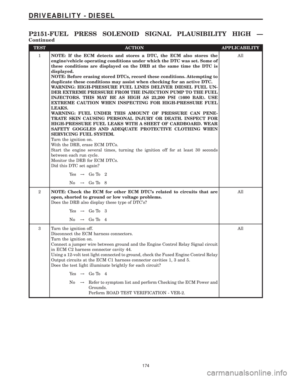
TEST ACTION APPLICABILITY
1NOTE: If the ECM detects and stores a DTC, the ECM also stores the
engine/vehicle operating conditions under which the DTC was set. Some of
these conditions are displayed on the DRB at the same time the DTC is
displayed.
NOTE: Before erasing stored DTCs, record these conditions. Attempting to
duplicate these conditions may assist when checking for an active DTC.
WARNING: HIGH-PRESSURE FUEL LINES DELIVER DIESEL FUEL UN-
DER EXTREME PRESSURE FROM THE INJECTION PUMP TO THE FUEL
INJECTORS. THIS MAY BE AS HIGH AS 23,200 PSI (1600 BAR). USE
EXTREME CAUTION WHEN INSPECTING FOR HIGH-PRESSURE FUEL
LEAKS.
WARNING: FUEL UNDER THIS AMOUNT OF PRESSURE CAN PENE-
TRATE SKIN CAUSING PERSONAL INJURY OR DEATH. INSPECT FOR
HIGH-PRESSURE FUEL LEAKS WITH A SHEET OF CARDBOARD. WEAR
SAFETY GOGGLES AND ADEQUATE PROTECTIVE CLOTHING WHEN
SERVICING FUEL SYSTEM.
Turn the ignition on.
With the DRB, erase ECM DTCs.
Start the engine several times, turning the ignition off for at least 30 seconds
between each run cycle.
Monitor the DRB for ECM DTCs.
Did this DTC set again?All
Ye s!Go To 2
No!Go To 8
2NOTE: Check the ECM for other ECM DTC's related to circuits that are
open, shorted to ground or low voltage problems.
Does the DRB also display these type of DTC's?All
Ye s!Go To 3
No!Go To 4
3 Turn the ignition off.
Disconnect the ECM harness connectors.
Turn the ignition on.
Connect a jumper wire between ground and the Engine Control Relay Signal circuit
in ECM C2 harness connector cavity 44.
Using a 12-volt test light connected to ground, check the Fused Engine Control Relay
Output circuits at the ECM C1 harness connector cavities 1, 3 and 5.
Does the test light illuminate brightly for each circuit?All
Ye s!Go To 4
No!Refer to symptom list and perform Checking the ECM Power and
Grounds.
Perform ROAD TEST VERIFICATION - VER-2.
174
DRIVEABILITY - DIESEL
P2151-FUEL PRESS SOLENOID SIGNAL PLAUSIBILITY HIGH Ð
Continued
Page 621 of 2305

Symptom:
P2306-SENSOR SUPPLY 2 VOLTAGE IS TOO HIGH
POSSIBLE CAUSES
BOOST PRESSURE SENSOR
FUEL PRESSURE SENSOR
VISUAL WIRING AND CONNECTOR INSPECTION
INTERMITTENT CONDITION
SENSOR SUPPLY VOLTAGE 2 SHORTED TO VOLTAGE
ENGINE CONTROL MODULE
TEST ACTION APPLICABILITY
1NOTE: If the ECM detects and stores a DTC, the ECM also stores the
engine/vehicle operating conditions under which the DTC was set. Some of
these conditions are displayed on the DRB at the same time the DTC is
displayed.
NOTE: Before erasing stored DTCs, record these conditions. Attempting to
duplicate these conditions may assist when checking for an active DTC.
Turn the ignition on.
With the DRB, erase ECM DTCs.
Turn the ignition off for 10 seconds.
Start the engine.
Monitor the DRB for ECM DTCs.
Did this DTC set again?All
Ye s!Go To 2
No!Go To 6
2 Turn the ignition off.
Visually inspect the wiring and connectors associated with the Boost Pressure Sensor
and Fuel Pressure Sensor for problems that may result in a short circuit.
Were any problems found?All
Ye s!Repair or replace wiring/connectors as necessary.
Perform ROAD TEST VERIFICATION - VER-2.
No!Go To 3
3 Turn the ignition off.
Disconnect the Boost Pressure Sensor and Fuel Pressure Sensor harness connectors.
Disconnect the ECM harness connectors.
Remove the Engine Control Relay.
Connect a jumper wire between cavity 30 and cavity 87 of the Engine Control Relay
connector in Fuse Block No.1.
Turn the ignition on.
Measure the voltage at all circuits in the Fuel Pressure Sensor and Boost Pressure
Sensor harness connector cavities.
Is the voltage above 1.0 volt for any of the measurements?All
Ye s!Repair the circuit(s) that measured above 1.0 volt for a short to
voltage.
Perform ROAD TEST VERIFICATION - VER-2.
No!Go To 4
198
DRIVEABILITY - DIESEL
Page 659 of 2305
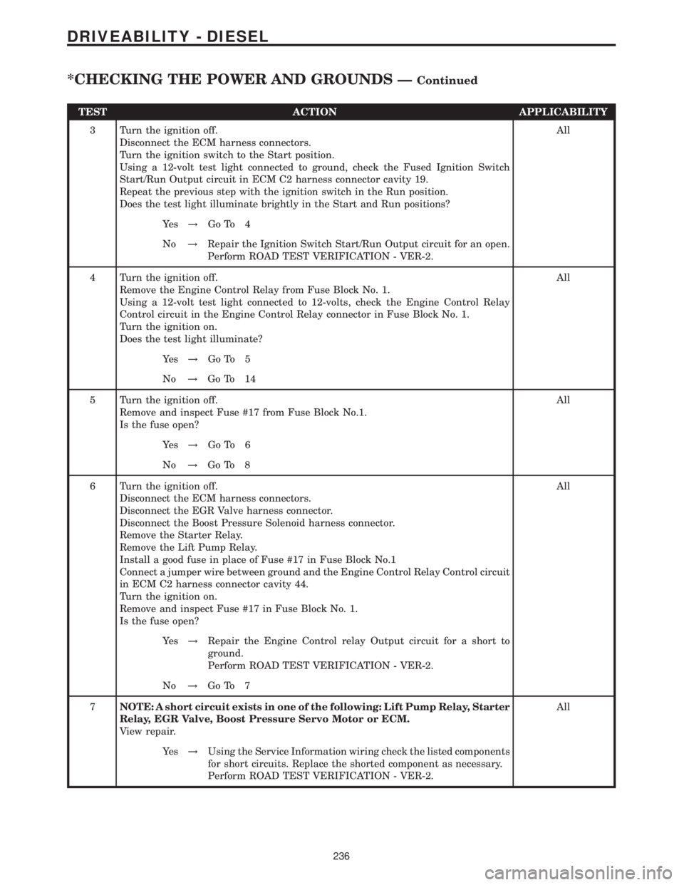
TEST ACTION APPLICABILITY
3 Turn the ignition off.
Disconnect the ECM harness connectors.
Turn the ignition switch to the Start position.
Using a 12-volt test light connected to ground, check the Fused Ignition Switch
Start/Run Output circuit in ECM C2 harness connector cavity 19.
Repeat the previous step with the ignition switch in the Run position.
Does the test light illuminate brightly in the Start and Run positions?All
Ye s!Go To 4
No!Repair the Ignition Switch Start/Run Output circuit for an open.
Perform ROAD TEST VERIFICATION - VER-2.
4 Turn the ignition off.
Remove the Engine Control Relay from Fuse Block No. 1.
Using a 12-volt test light connected to 12-volts, check the Engine Control Relay
Control circuit in the Engine Control Relay connector in Fuse Block No. 1.
Turn the ignition on.
Does the test light illuminate?All
Ye s!Go To 5
No!Go To 14
5 Turn the ignition off.
Remove and inspect Fuse #17 from Fuse Block No.1.
Is the fuse open?All
Ye s!Go To 6
No!Go To 8
6 Turn the ignition off.
Disconnect the ECM harness connectors.
Disconnect the EGR Valve harness connector.
Disconnect the Boost Pressure Solenoid harness connector.
Remove the Starter Relay.
Remove the Lift Pump Relay.
Install a good fuse in place of Fuse #17 in Fuse Block No.1
Connect a jumper wire between ground and the Engine Control Relay Control circuit
in ECM C2 harness connector cavity 44.
Turn the ignition on.
Remove and inspect Fuse #17 in Fuse Block No. 1.
Is the fuse open?All
Ye s!Repair the Engine Control relay Output circuit for a short to
ground.
Perform ROAD TEST VERIFICATION - VER-2.
No!Go To 7
7NOTE: A short circuit exists in one of the following: Lift Pump Relay, Starter
Relay, EGR Valve, Boost Pressure Servo Motor or ECM.
View repair.All
Ye s!Using the Service Information wiring check the listed components
for short circuits. Replace the shorted component as necessary.
Perform ROAD TEST VERIFICATION - VER-2.
236
DRIVEABILITY - DIESEL
*CHECKING THE POWER AND GROUNDS ÐContinued
Page 667 of 2305
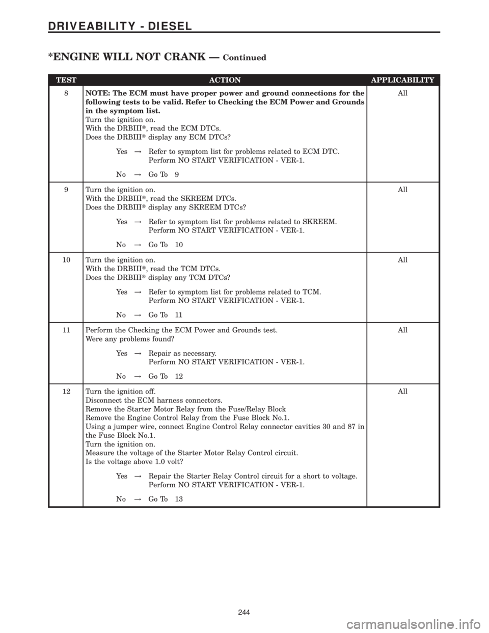
TEST ACTION APPLICABILITY
8NOTE: The ECM must have proper power and ground connections for the
following tests to be valid. Refer to Checking the ECM Power and Grounds
in the symptom list.
Turn the ignition on.
With the DRBIIIt, read the ECM DTCs.
Does the DRBIIItdisplay any ECM DTCs?All
Ye s!Refer to symptom list for problems related to ECM DTC.
Perform NO START VERIFICATION - VER-1.
No!Go To 9
9 Turn the ignition on.
With the DRBIIIt, read the SKREEM DTCs.
Does the DRBIIItdisplay any SKREEM DTCs?All
Ye s!Refer to symptom list for problems related to SKREEM.
Perform NO START VERIFICATION - VER-1.
No!Go To 10
10 Turn the ignition on.
With the DRBIIIt, read the TCM DTCs.
Does the DRBIIItdisplay any TCM DTCs?All
Ye s!Refer to symptom list for problems related to TCM.
Perform NO START VERIFICATION - VER-1.
No!Go To 11
11 Perform the Checking the ECM Power and Grounds test.
Were any problems found?All
Ye s!Repair as necessary.
Perform NO START VERIFICATION - VER-1.
No!Go To 12
12 Turn the ignition off.
Disconnect the ECM harness connectors.
Remove the Starter Motor Relay from the Fuse/Relay Block
Remove the Engine Control Relay from the Fuse Block No.1.
Using a jumper wire, connect Engine Control Relay connector cavities 30 and 87 in
the Fuse Block No.1.
Turn the ignition on.
Measure the voltage of the Starter Motor Relay Control circuit.
Is the voltage above 1.0 volt?All
Ye s!Repair the Starter Relay Control circuit for a short to voltage.
Perform NO START VERIFICATION - VER-1.
No!Go To 13
244
DRIVEABILITY - DIESEL
*ENGINE WILL NOT CRANK ÐContinued
Page 669 of 2305
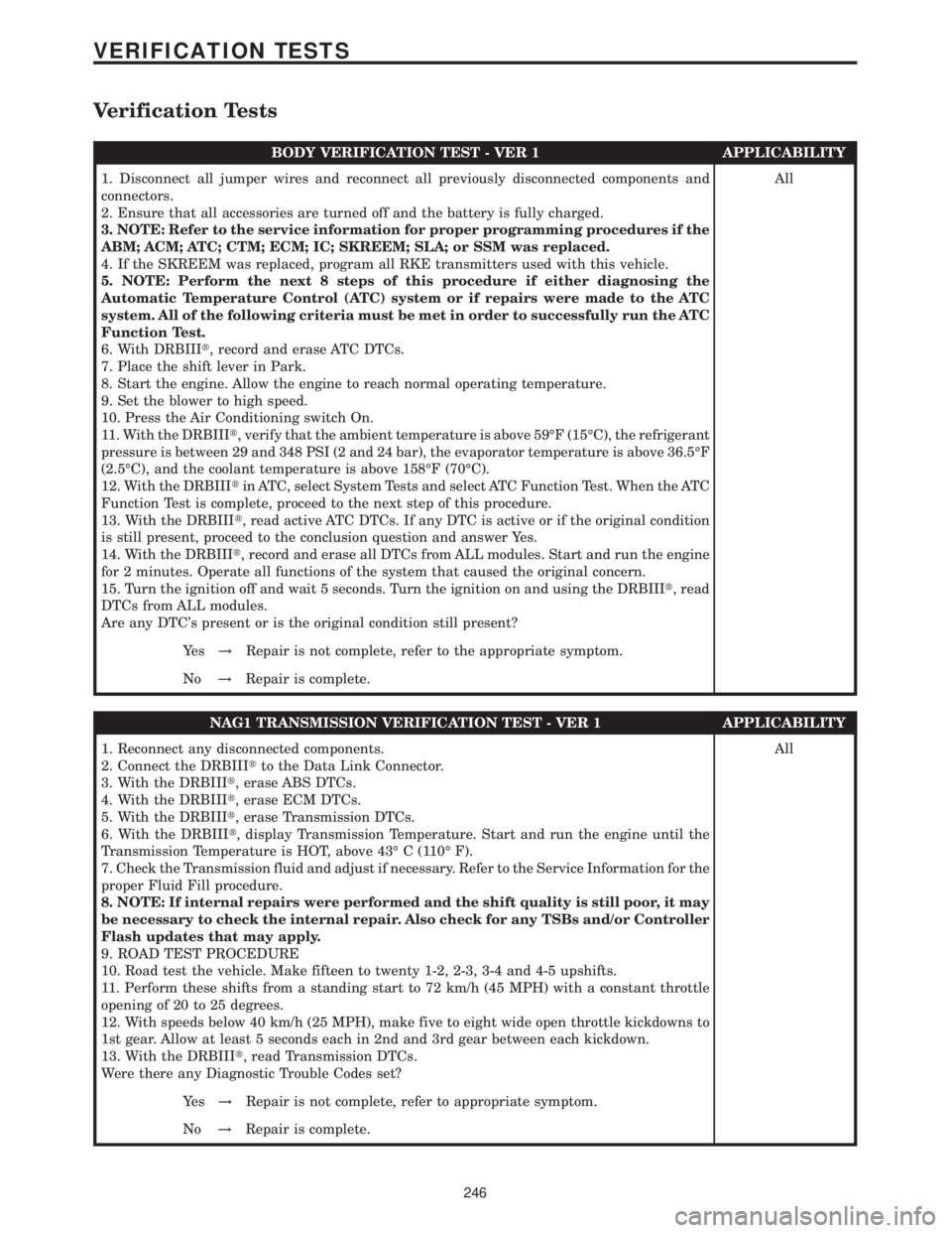
Verification Tests
BODY VERIFICATION TEST - VER 1 APPLICABILITY
1. Disconnect all jumper wires and reconnect all previously disconnected components and
connectors.
2. Ensure that all accessories are turned off and the battery is fully charged.
3. NOTE: Refer to the service information for proper programming procedures if the
ABM; ACM; ATC; CTM; ECM; IC; SKREEM; SLA; or SSM was replaced.
4. If the SKREEM was replaced, program all RKE transmitters used with this vehicle.
5. NOTE: Perform the next 8 steps of this procedure if either diagnosing the
Automatic Temperature Control (ATC) system or if repairs were made to the ATC
system. All of the following criteria must be met in order to successfully run the ATC
Function Test.
6. With DRBIIIt, record and erase ATC DTCs.
7. Place the shift lever in Park.
8. Start the engine. Allow the engine to reach normal operating temperature.
9. Set the blower to high speed.
10. Press the Air Conditioning switch On.
11. With the DRBIIIt, verify that the ambient temperature is above 59ÉF (15ÉC), the refrigerant
pressure is between 29 and 348 PSI (2 and 24 bar), the evaporator temperature is above 36.5ÉF
(2.5ÉC), and the coolant temperature is above 158ÉF (70ÉC).
12. With the DRBIIItin ATC, select System Tests and select ATC Function Test. When the ATC
Function Test is complete, proceed to the next step of this procedure.
13. With the DRBIIIt, read active ATC DTCs. If any DTC is active or if the original condition
is still present, proceed to the conclusion question and answer Yes.
14. With the DRBIIIt, record and erase all DTCs from ALL modules. Start and run the engine
for 2 minutes. Operate all functions of the system that caused the original concern.
15. Turn the ignition off and wait 5 seconds. Turn the ignition on and using the DRBIIIt, read
DTCs from ALL modules.
Are any DTC's present or is the original condition still present?All
Ye s!Repair is not complete, refer to the appropriate symptom.
No!Repair is complete.
NAG1 TRANSMISSION VERIFICATION TEST - VER 1 APPLICABILITY
1. Reconnect any disconnected components.
2. Connect the DRBIIItto the Data Link Connector.
3. With the DRBIIIt, erase ABS DTCs.
4. With the DRBIIIt, erase ECM DTCs.
5. With the DRBIIIt, erase Transmission DTCs.
6. With the DRBIIIt, display Transmission Temperature. Start and run the engine until the
Transmission Temperature is HOT, above 43É C (110É F).
7. Check the Transmission fluid and adjust if necessary. Refer to the Service Information for the
proper Fluid Fill procedure.
8. NOTE: If internal repairs were performed and the shift quality is still poor, it may
be necessary to check the internal repair. Also check for any TSBs and/or Controller
Flash updates that may apply.
9. ROAD TEST PROCEDURE
10. Road test the vehicle. Make fifteen to twenty 1-2, 2-3, 3-4 and 4-5 upshifts.
11. Perform these shifts from a standing start to 72 km/h (45 MPH) with a constant throttle
opening of 20 to 25 degrees.
12. With speeds below 40 km/h (25 MPH), make five to eight wide open throttle kickdowns to
1st gear. Allow at least 5 seconds each in 2nd and 3rd gear between each kickdown.
13. With the DRBIIIt, read Transmission DTCs.
Were there any Diagnostic Trouble Codes set?All
Ye s!Repair is not complete, refer to appropriate symptom.
No!Repair is complete.
246
VERIFICATION TESTS
Page 716 of 2305
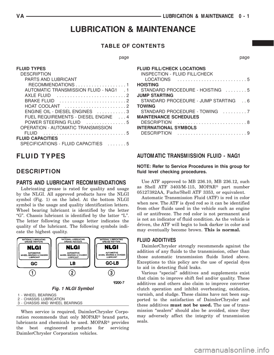
LUBRICATION & MAINTENANCE
TABLE OF CONTENTS
page page
FLUID TYPES
DESCRIPTION
PARTS AND LUBRICANT
RECOMMENDATIONS...................1
AUTOMATIC TRANSMISSION FLUID - NAG1 . 1
AXLE FLUID..........................2
BRAKE FLUID.........................2
HOAT COOLANT.......................2
ENGINE OIL - DIESEL ENGINES...........3
FUEL REQUIREMENTS - DIESEL ENGINE . . . 4
POWER STEERING FLUID...............5
OPERATION - AUTOMATIC TRANSMISSION
FLUID...............................5
FLUID CAPACITIES
SPECIFICATIONS - FLUID CAPACITIES.......5FLUID FILL/CHECK LOCATIONS
INSPECTION - FLUID FILL/CHECK
LOCATIONS..........................5
HOISTING
STANDARD PROCEDURE - HOISTING........5
JUMP STARTING
STANDARD PROCEDURE - JUMP STARTING . . 6
TOWING
STANDARD PROCEDURE - TOWING.........7
MAINTENANCE SCHEDULES
DESCRIPTION..........................8
INTERNATIONAL SYMBOLS
DESCRIPTION..........................9
FLUID TYPES
DESCRIPTION
PARTS AND LUBRICANT RECOMMENDATIONS
Lubricating grease is rated for quality and usage
by the NLGI. All approved products have the NLGI
symbol (Fig. 1) on the label. At the bottom NLGI
symbol is the usage and quality identification letters.
Wheel bearing lubricant is identified by the letter
ªGº. Chassis lubricant is identified by the latter ªLº.
The letter following the usage letter indicates the
quality of the lubricant. The following symbols indi-
cate the highest quality.
When service is required, DaimlerChrysler Corpo-
ration recommends that only MOPARtbrand parts,
lubricants and chemicals be used. MOPARtprovides
the best engineered products for servicing
DaimlerChrysler Corporation vehicles.
AUTOMATIC TRANSMISSION FLUID - NAG1
NOTE: Refer to Service Procedures in this group for
fluid level checking procedures.
Use ATF approved to MB 236.10, MB 236.12, such
as Shell ATF 3403/M-115, MOPARtpart number
05127382AA, Fuchs/Shell ATF 3353, or equivalent.
Automatic Transmission Fluid (ATF) is red in color
when new. The ATF is dyed red so it can be identified
from other fluids used in the vehicle such as engine
oil or antifreeze. The red color is not permanent and
is not an indicator of fluid condition. As the vehicle is
driven, the ATF will begin to look darker in color and
may eventually become brown.This is normal.
FLUID ADDITIVES
DaimlerChrysler strongly recommends against the
addition of any fluids to the transmission, other than
those automatic transmission fluids listed above.
Exceptions to this policy are the use of special dyes
to aid in detecting fluid leaks.
Various ªspecialº additives and supplements exist
that claim to improve shift feel and/or quality. These
additives and others also claim to improve converter
clutch operation and inhibit overheating, oxidation,
varnish, and sludge. These claims have not been sup-
ported to the satisfaction of DaimlerChrysler and
these additivesmust not be used.The use of trans-
mission ªsealersº should also be avoided, since they
may adversely affect the integrity of transmission
seals.
Fig. 1 NLGI Symbol
1 - WHEEL BEARINGS
2 - CHASSIS LUBRICATION
3 - CHASSIS AND WHEEL BEARINGS
VALUBRICATION & MAINTENANCE 0 - 1
Page 721 of 2305
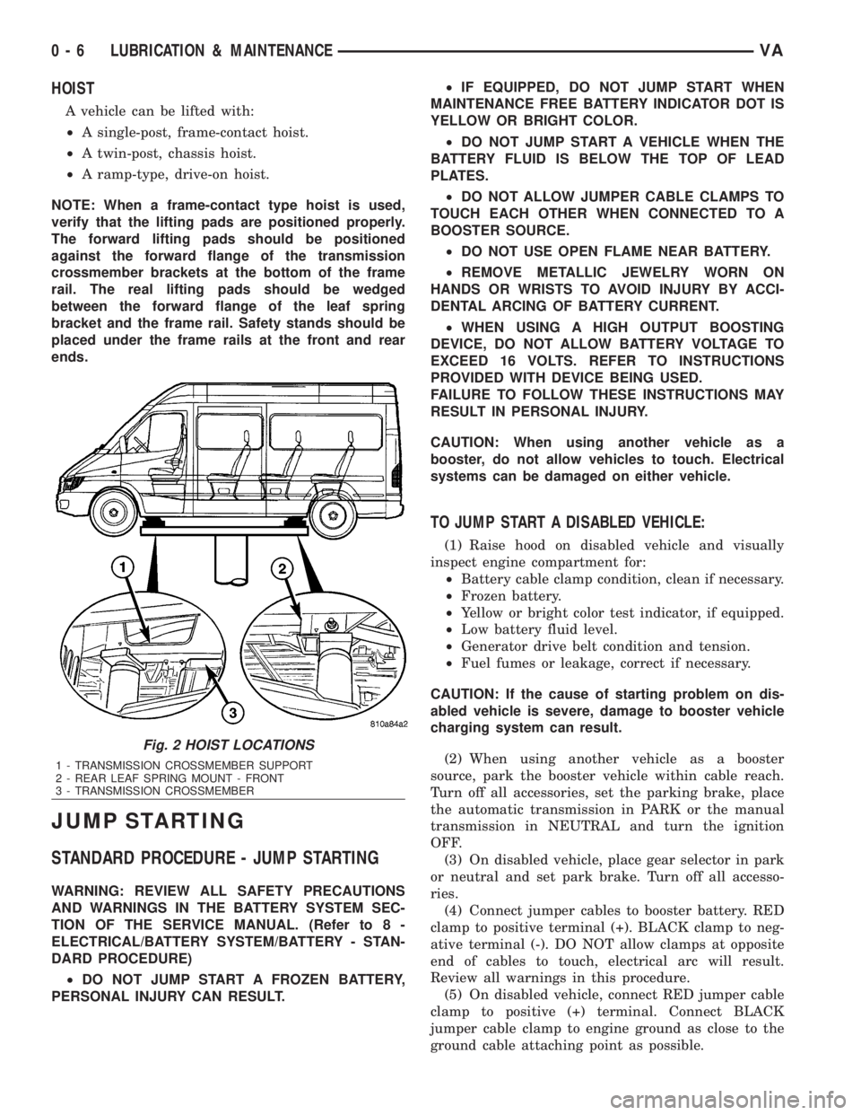
HOIST
A vehicle can be lifted with:
²A single-post, frame-contact hoist.
²A twin-post, chassis hoist.
²A ramp-type, drive-on hoist.
NOTE: When a frame-contact type hoist is used,
verify that the lifting pads are positioned properly.
The forward lifting pads should be positioned
against the forward flange of the transmission
crossmember brackets at the bottom of the frame
rail. The real lifting pads should be wedged
between the forward flange of the leaf spring
bracket and the frame rail. Safety stands should be
placed under the frame rails at the front and rear
ends.
JUMP STARTING
STANDARD PROCEDURE - JUMP STARTING
WARNING: REVIEW ALL SAFETY PRECAUTIONS
AND WARNINGS IN THE BATTERY SYSTEM SEC-
TION OF THE SERVICE MANUAL. (Refer to 8 -
ELECTRICAL/BATTERY SYSTEM/BATTERY - STAN-
DARD PROCEDURE)
²DO NOT JUMP START A FROZEN BATTERY,
PERSONAL INJURY CAN RESULT.²IF EQUIPPED, DO NOT JUMP START WHEN
MAINTENANCE FREE BATTERY INDICATOR DOT IS
YELLOW OR BRIGHT COLOR.
²DO NOT JUMP START A VEHICLE WHEN THE
BATTERY FLUID IS BELOW THE TOP OF LEAD
PLATES.
²DO NOT ALLOW JUMPER CABLE CLAMPS TO
TOUCH EACH OTHER WHEN CONNECTED TO A
BOOSTER SOURCE.
²DO NOT USE OPEN FLAME NEAR BATTERY.
²REMOVE METALLIC JEWELRY WORN ON
HANDS OR WRISTS TO AVOID INJURY BY ACCI-
DENTAL ARCING OF BATTERY CURRENT.
²WHEN USING A HIGH OUTPUT BOOSTING
DEVICE, DO NOT ALLOW BATTERY VOLTAGE TO
EXCEED 16 VOLTS. REFER TO INSTRUCTIONS
PROVIDED WITH DEVICE BEING USED.
FAILURE TO FOLLOW THESE INSTRUCTIONS MAY
RESULT IN PERSONAL INJURY.
CAUTION: When using another vehicle as a
booster, do not allow vehicles to touch. Electrical
systems can be damaged on either vehicle.
TO JUMP START A DISABLED VEHICLE:
(1) Raise hood on disabled vehicle and visually
inspect engine compartment for:
²Battery cable clamp condition, clean if necessary.
²Frozen battery.
²Yellow or bright color test indicator, if equipped.
²Low battery fluid level.
²Generator drive belt condition and tension.
²Fuel fumes or leakage, correct if necessary.
CAUTION: If the cause of starting problem on dis-
abled vehicle is severe, damage to booster vehicle
charging system can result.
(2) When using another vehicle as a booster
source, park the booster vehicle within cable reach.
Turn off all accessories, set the parking brake, place
the automatic transmission in PARK or the manual
transmission in NEUTRAL and turn the ignition
OFF.
(3) On disabled vehicle, place gear selector in park
or neutral and set park brake. Turn off all accesso-
ries.
(4) Connect jumper cables to booster battery. RED
clamp to positive terminal (+). BLACK clamp to neg-
ative terminal (-). DO NOT allow clamps at opposite
end of cables to touch, electrical arc will result.
Review all warnings in this procedure.
(5) On disabled vehicle, connect RED jumper cable
clamp to positive (+) terminal. Connect BLACK
jumper cable clamp to engine ground as close to the
ground cable attaching point as possible.
Fig. 2 HOIST LOCATIONS
1 - TRANSMISSION CROSSMEMBER SUPPORT
2 - REAR LEAF SPRING MOUNT - FRONT
3 - TRANSMISSION CROSSMEMBER
0 - 6 LUBRICATION & MAINTENANCEVA