2006 MERCEDES-BENZ SPRINTER timing belt
[x] Cancel search: timing beltPage 564 of 2305

TEST ACTION APPLICABILITY
1NOTE: If DTC P1611, P2306 or P2332 is present with this DTC, diagnose
DTCs P1611, P2306 or P2332 before diagnosing this DTC.
NOTE: The Timing Belt/Chain must be correctly installed and operational
before diagnosis can be made. Refer to the Service Information to ensure
the timing belt is properly installed.
NOTE: If the ECM detects and stores a DTC, the ECM also stores the
engine/vehicle operating conditions under which the DTC was set. Some of
these conditions are displayed on the DRB at the same time the DTC is
displayed.
NOTE: Before erasing stored DTCs, record these conditions. Attempting to
duplicate these conditions may assist when checking for an active DTC.
Turn the ignition on.
With the DRBIIIt, erase the ECM DTCs.
Attempt to start the engine cranking the engine for at least 7 seconds.
With the DRBIIIt, read the ECM DTCs.
Does the DRBIIItdisplay this DTC?All
Ye s!Go To 4
No!Go To 2
2 Turn the ignition on.
With the DRBIIIt, erase the ECM DTCs.
Test drive the vehicle.
With the DRBIIIt, read the ECM DTCs.
Does the DRBIIItdisplay this DTC?All
Ye s!Go To 3
No!Go To 16
3 Turn the ignition off.
Disconnect the Camshaft Position Sensor harness connector.
Turn the ignition on.
Measure the voltage of the CMP Sensor Signal circuit.
Select the appropriate voltage reading.All
Voltage is above 5.4 volts.
Go To 4
Voltage is between 4.7 and 5.4 volts.
Go To 5
Voltage is below 4.7 volts.
Go To 13
141
DRIVEABILITY - DIESEL
P2043-CAMSHAFT POSITION SENSOR CIRCUIT OPEN CIRCUIT Ð
Continued
Page 828 of 2305
COOLING
TABLE OF CONTENTS
page page
COOLING
OPERATION - COOLING SYSTEM...........1
DIAGNOSIS AND TESTING
DIAGNOSIS AND TESTING - PRELIMINARY
CHECKS.............................1COOLING SYSTEM.....................2
ACCESSORY DRIVE.......................5
ENGINE.................................9
COOLING
OPERATION - COOLING SYSTEM
The cooling system regulates engine operating tem-
perature. It allows the engine to reach normal oper-
ating temperature as quickly as possible. It also
maintains normal operating temperature and pre-
vents overheating.
The cooling system also provides a means of heat-
ing the passenger compartment and cooling the auto-
matic transmission fluid (if equipped). The cooling
system is pressurized and uses a centrifugal water
pump to circulate coolant throughout the system.
DIAGNOSIS AND TESTING
DIAGNOSIS AND TESTING - PRELIMINARY
CHECKS
ENGINE COOLING SYSTEM OVERHEATING
Establish what driving conditions caused the com-
plaint. Abnormal loads on the cooling system such as
the following may be the cause:
²PROLONGED IDLE
²VERY HIGH AMBIENT TEMPERATURE
²SLIGHT TAIL WIND AT IDLE
²SLOW TRAFFIC
²TRAFFIC JAMS
²HIGH SPEED OR STEEP GRADES
Driving techniques that avoid overheating are:
²Idle with A/C off when temperature gauge is at
end of normal range.²Increasing engine speed for more air flow is rec-
ommended.
TRAILER TOWING:
Consult Trailer Towing section of owners manual.
Do not exceed limits.
AIR CONDITIONING; ADD - ON OR AFTER MARKET:
A maximum cooling package should have been
ordered with vehicle if add-on or after market A/C is
installed. If not, maximum cooling system compo-
nents should be installed for model involved per
manufacturer's specifications.
RECENT SERVICE OR ACCIDENT REPAIR:
Determine if any recent service has been per-
formed on vehicle that may effect cooling system.
This may be:
²Engine adjustments (incorrect timing)
²Slipping engine accessory drive belt(s)
²Brakes (possibly dragging)
²Changed parts. Incorrect water pump or pump
rotating in wrong direction due to belt not correctly
routed
²Reconditioned radiator or cooling system refill-
ing (possibly under filled or air trapped in system).
NOTE: If investigation reveals none of the previous
items as a cause for an engine overheating com-
plaint, (Refer to 7 - COOLING - DIAGNOSIS AND
TESTING)
VACOOLING 7 - 1
Page 1588 of 2305
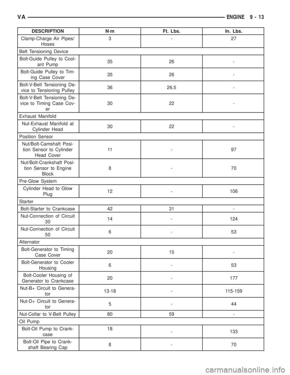
DESCRIPTION N´m Ft. Lbs. In. Lbs.
Clamp-Charge Air Pipes/
Hoses3-27
Belt Tensioning Device
Bolt-Guide Pulley to Cool-
ant Pump35 26 -
Bolt-Guide Pulley to Tim-
ing Case Cover35 26 -
Bolt-V-Belt Tensioning De-
vice to Tensioning Pulley36 26.5 -
Bolt-V-Belt Tensioning De-
vice to Timing Case Cov-
er30 22 -
Exhaust Manifold
Nut-Exhaust Manifold at
Cylinder Head30 22 -
Position Sensor
Nut/Bolt-Camshaft Posi-
tion Sensor to Cylinder
Head Cover11 - 9 7
Nut/Bolt-Crankshaft Posi-
tion Sensor to Engine
Block8-70
Pre-Glow System
Cylinder Head to Glow
Plug12 - 106
Starter
Bolt-Starter to Crankcase 42 31 -
Nut-Connection of Circuit
3014 - 124
Nut-Connection of Circuit
506-53
Alternator
Bolt-Generator to Timing
Case Cover20 15 -
Bolt-Generator to Cooler
Housing6-53
Bolt-Cooler Housing of
Generator to Crankcase20 - 177
Nut-B+ Circuit to Genera-
tor13-18 - 115-159
Nut-D+ Circuit to Genera-
tor5-44
Nut-Collar to V-Belt Pulley 80 59 -
Oil Pump
Bolt-Oil Pump to Crank-
case18
- 133
Bolt-Oil Pipe to Crank-
shaft Bearing Cap8-70
VAENGINE 9 - 13
Page 1589 of 2305
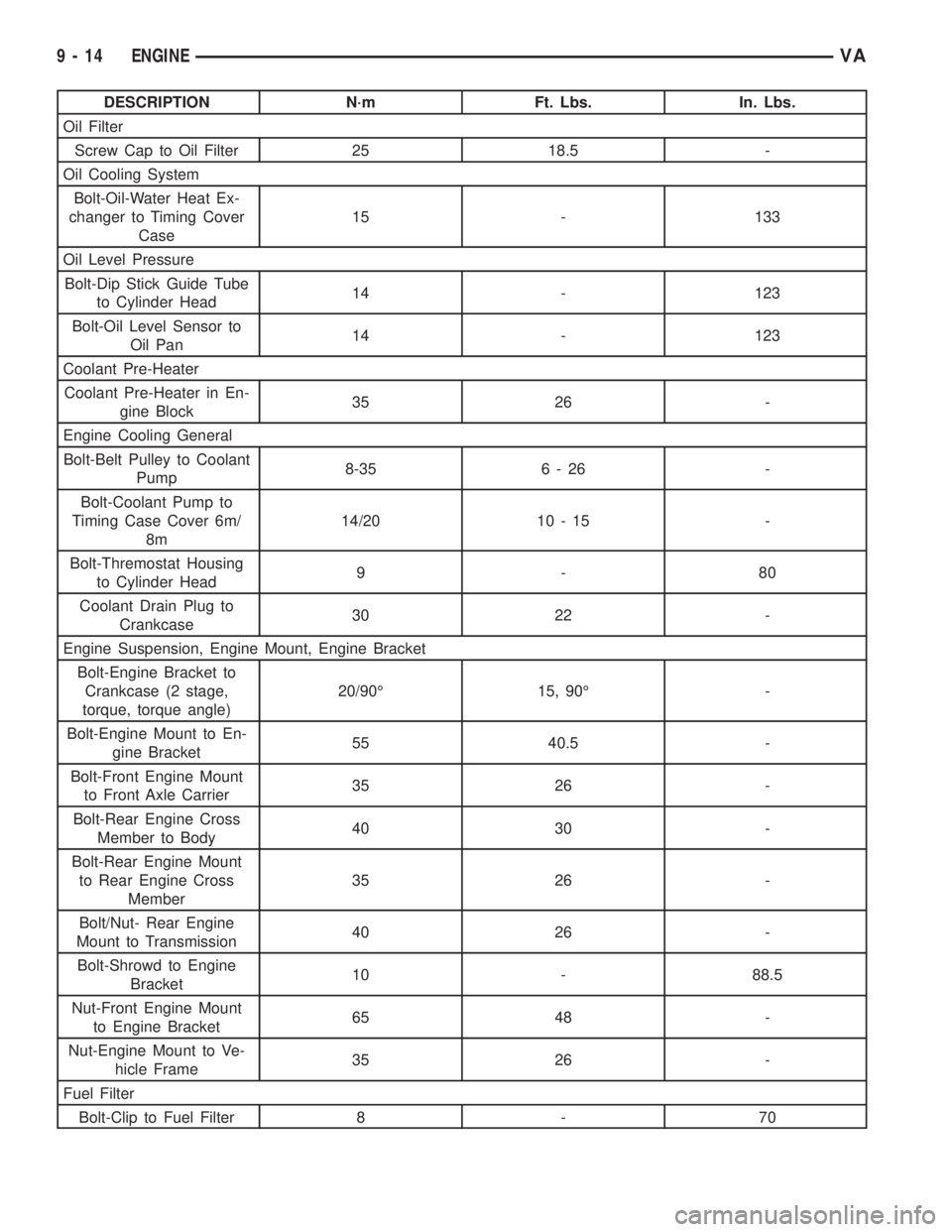
DESCRIPTION N´m Ft. Lbs. In. Lbs.
Oil Filter
Screw Cap to Oil Filter 25 18.5 -
Oil Cooling System
Bolt-Oil-Water Heat Ex-
changer to Timing Cover
Case15 - 133
Oil Level Pressure
Bolt-Dip Stick Guide Tube
to Cylinder Head14 - 123
Bolt-Oil Level Sensor to
Oil Pan14 - 123
Coolant Pre-Heater
Coolant Pre-Heater in En-
gine Block35 26 -
Engine Cooling General
Bolt-Belt Pulley to Coolant
Pump8-35 6 - 26 -
Bolt-Coolant Pump to
Timing Case Cover 6m/
8m14/20 10 - 15 -
Bolt-Thremostat Housing
to Cylinder Head9-80
Coolant Drain Plug to
Crankcase30 22 -
Engine Suspension, Engine Mount, Engine Bracket
Bolt-Engine Bracket to
Crankcase (2 stage,
torque, torque angle)20/90É 15, 90É -
Bolt-Engine Mount to En-
gine Bracket55 40.5 -
Bolt-Front Engine Mount
to Front Axle Carrier35 26 -
Bolt-Rear Engine Cross
Member to Body40 30 -
Bolt-Rear Engine Mount
to Rear Engine Cross
Member35 26 -
Bolt/Nut- Rear Engine
Mount to Transmission40 26 -
Bolt-Shrowd to Engine
Bracket10 - 88.5
Nut-Front Engine Mount
to Engine Bracket65 48 -
Nut-Engine Mount to Ve-
hicle Frame35 26 -
Fuel Filter
Bolt-Clip to Fuel Filter 8 - 70
9 - 14 ENGINEVA
Page 1600 of 2305
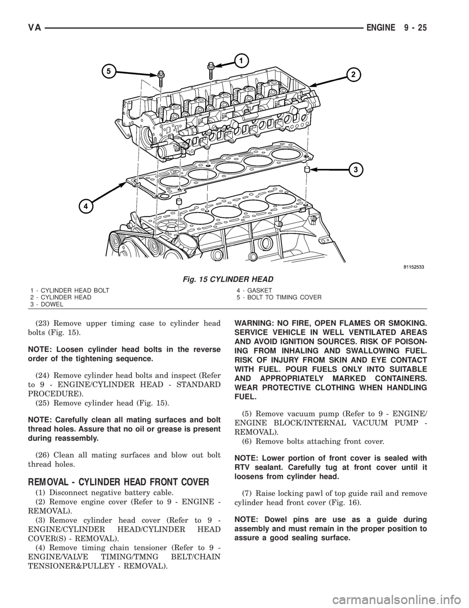
(23) Remove upper timing case to cylinder head
bolts (Fig. 15).
NOTE: Loosen cylinder head bolts in the reverse
order of the tightening sequence.
(24) Remove cylinder head bolts and inspect (Refer
to 9 - ENGINE/CYLINDER HEAD - STANDARD
PROCEDURE).
(25) Remove cylinder head (Fig. 15).
NOTE: Carefully clean all mating surfaces and bolt
thread holes. Assure that no oil or grease is present
during reassembly.
(26) Clean all mating surfaces and blow out bolt
thread holes.
REMOVAL - CYLINDER HEAD FRONT COVER
(1) Disconnect negative battery cable.
(2) Remove engine cover (Refer to 9 - ENGINE -
REMOVAL).
(3) Remove cylinder head cover (Refer to 9 -
ENGINE/CYLINDER HEAD/CYLINDER HEAD
COVER(S) - REMOVAL).
(4) Remove timing chain tensioner (Refer to 9 -
ENGINE/VALVE TIMING/TMNG BELT/CHAIN
TENSIONER&PULLEY - REMOVAL).WARNING: NO FIRE, OPEN FLAMES OR SMOKING.
SERVICE VEHICLE IN WELL VENTILATED AREAS
AND AVOID IGNITION SOURCES. RISK OF POISON-
ING FROM INHALING AND SWALLOWING FUEL.
RISK OF INJURY FROM SKIN AND EYE CONTACT
WITH FUEL. POUR FUELS ONLY INTO SUITABLE
AND APPROPRIATELY MARKED CONTAINERS.
WEAR PROTECTIVE CLOTHING WHEN HANDLING
FUEL.
(5) Remove vacuum pump (Refer to 9 - ENGINE/
ENGINE BLOCK/INTERNAL VACUUM PUMP -
REMOVAL).
(6) Remove bolts attaching front cover.
NOTE: Lower portion of front cover is sealed with
RTV sealant. Carefully tug at front cover until it
loosens from cylinder head.
(7) Raise locking pawl of top guide rail and remove
cylinder head front cover (Fig. 16).
NOTE: Dowel pins are use as a guide during
assembly and must remain in the proper position to
assure a good sealing surface.
Fig. 15 CYLINDER HEAD
1 - CYLINDER HEAD BOLT
2 - CYLINDER HEAD
3 - DOWEL4 - GASKET
5 - BOLT TO TIMING COVER
VAENGINE 9 - 25
Page 1601 of 2305
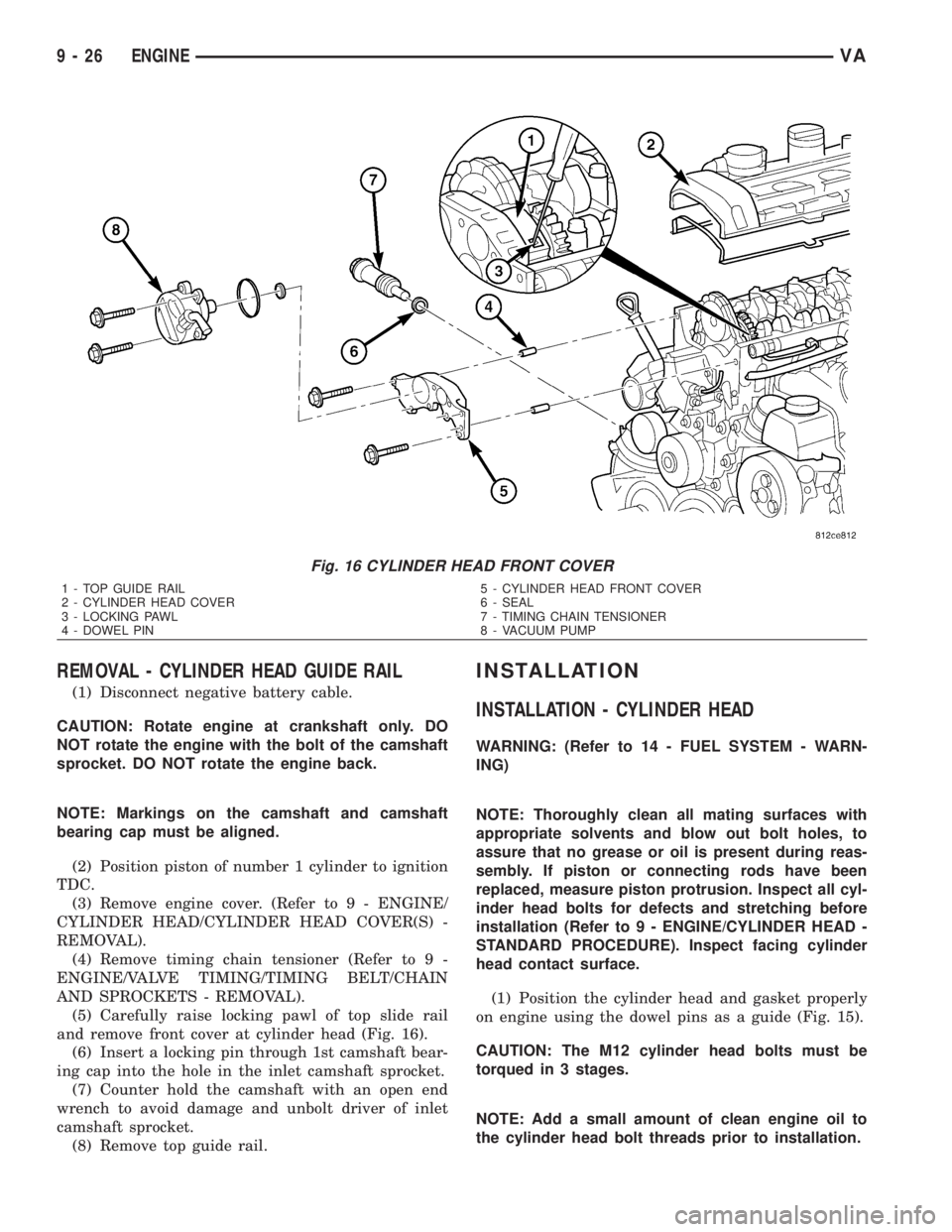
REMOVAL - CYLINDER HEAD GUIDE RAIL
(1) Disconnect negative battery cable.
CAUTION: Rotate engine at crankshaft only. DO
NOT rotate the engine with the bolt of the camshaft
sprocket. DO NOT rotate the engine back.
NOTE: Markings on the camshaft and camshaft
bearing cap must be aligned.
(2) Position piston of number 1 cylinder to ignition
TDC.
(3) Remove engine cover. (Refer to 9 - ENGINE/
CYLINDER HEAD/CYLINDER HEAD COVER(S) -
REMOVAL).
(4) Remove timing chain tensioner (Refer to 9 -
ENGINE/VALVE TIMING/TIMING BELT/CHAIN
AND SPROCKETS - REMOVAL).
(5) Carefully raise locking pawl of top slide rail
and remove front cover at cylinder head (Fig. 16).
(6) Insert a locking pin through 1st camshaft bear-
ing cap into the hole in the inlet camshaft sprocket.
(7) Counter hold the camshaft with an open end
wrench to avoid damage and unbolt driver of inlet
camshaft sprocket.
(8) Remove top guide rail.
INSTALLATION
INSTALLATION - CYLINDER HEAD
WARNING: (Refer to 14 - FUEL SYSTEM - WARN-
ING)
NOTE: Thoroughly clean all mating surfaces with
appropriate solvents and blow out bolt holes, to
assure that no grease or oil is present during reas-
sembly. If piston or connecting rods have been
replaced, measure piston protrusion. Inspect all cyl-
inder head bolts for defects and stretching before
installation (Refer to 9 - ENGINE/CYLINDER HEAD -
STANDARD PROCEDURE). Inspect facing cylinder
head contact surface.
(1) Position the cylinder head and gasket properly
on engine using the dowel pins as a guide (Fig. 15).
CAUTION: The M12 cylinder head bolts must be
torqued in 3 stages.
NOTE: Add a small amount of clean engine oil to
the cylinder head bolt threads prior to installation.
Fig. 16 CYLINDER HEAD FRONT COVER
1 - TOP GUIDE RAIL
2 - CYLINDER HEAD COVER
3 - LOCKING PAWL
4 - DOWEL PIN5 - CYLINDER HEAD FRONT COVER
6 - SEAL
7 - TIMING CHAIN TENSIONER
8 - VACUUM PUMP
9 - 26 ENGINEVA
Page 1602 of 2305
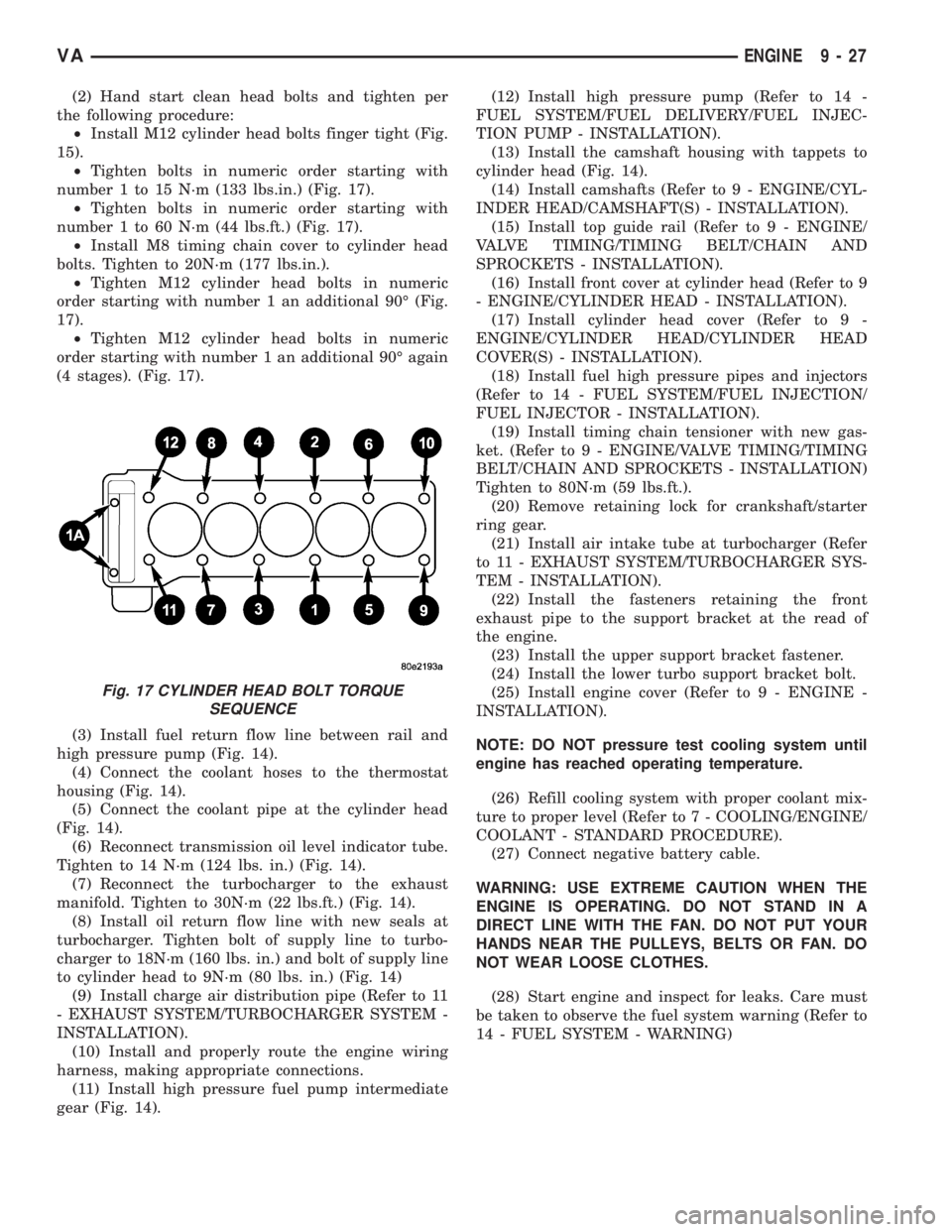
(2) Hand start clean head bolts and tighten per
the following procedure:
²Install M12 cylinder head bolts finger tight (Fig.
15).
²Tighten bolts in numeric order starting with
number 1 to 15 N´m (133 lbs.in.) (Fig. 17).
²Tighten bolts in numeric order starting with
number 1 to 60 N´m (44 lbs.ft.) (Fig. 17).
²Install M8 timing chain cover to cylinder head
bolts. Tighten to 20N´m (177 lbs.in.).
²Tighten M12 cylinder head bolts in numeric
order starting with number 1 an additional 90É (Fig.
17).
²Tighten M12 cylinder head bolts in numeric
order starting with number 1 an additional 90É again
(4 stages). (Fig. 17).
(3) Install fuel return flow line between rail and
high pressure pump (Fig. 14).
(4) Connect the coolant hoses to the thermostat
housing (Fig. 14).
(5) Connect the coolant pipe at the cylinder head
(Fig. 14).
(6) Reconnect transmission oil level indicator tube.
Tighten to 14 N´m (124 lbs. in.) (Fig. 14).
(7) Reconnect the turbocharger to the exhaust
manifold. Tighten to 30N´m (22 lbs.ft.) (Fig. 14).
(8) Install oil return flow line with new seals at
turbocharger. Tighten bolt of supply line to turbo-
charger to 18N´m (160 lbs. in.) and bolt of supply line
to cylinder head to 9N´m (80 lbs. in.) (Fig. 14)
(9) Install charge air distribution pipe (Refer to 11
- EXHAUST SYSTEM/TURBOCHARGER SYSTEM -
INSTALLATION).
(10) Install and properly route the engine wiring
harness, making appropriate connections.
(11) Install high pressure fuel pump intermediate
gear (Fig. 14).(12) Install high pressure pump (Refer to 14 -
FUEL SYSTEM/FUEL DELIVERY/FUEL INJEC-
TION PUMP - INSTALLATION).
(13) Install the camshaft housing with tappets to
cylinder head (Fig. 14).
(14) Install camshafts (Refer to 9 - ENGINE/CYL-
INDER HEAD/CAMSHAFT(S) - INSTALLATION).
(15) Install top guide rail (Refer to 9 - ENGINE/
VALVE TIMING/TIMING BELT/CHAIN AND
SPROCKETS - INSTALLATION).
(16) Install front cover at cylinder head (Refer to 9
- ENGINE/CYLINDER HEAD - INSTALLATION).
(17) Install cylinder head cover (Refer to 9 -
ENGINE/CYLINDER HEAD/CYLINDER HEAD
COVER(S) - INSTALLATION).
(18) Install fuel high pressure pipes and injectors
(Refer to 14 - FUEL SYSTEM/FUEL INJECTION/
FUEL INJECTOR - INSTALLATION).
(19) Install timing chain tensioner with new gas-
ket. (Refer to 9 - ENGINE/VALVE TIMING/TIMING
BELT/CHAIN AND SPROCKETS - INSTALLATION)
Tighten to 80N´m (59 lbs.ft.).
(20) Remove retaining lock for crankshaft/starter
ring gear.
(21) Install air intake tube at turbocharger (Refer
to 11 - EXHAUST SYSTEM/TURBOCHARGER SYS-
TEM - INSTALLATION).
(22) Install the fasteners retaining the front
exhaust pipe to the support bracket at the read of
the engine.
(23) Install the upper support bracket fastener.
(24) Install the lower turbo support bracket bolt.
(25) Install engine cover (Refer to 9 - ENGINE -
INSTALLATION).
NOTE: DO NOT pressure test cooling system until
engine has reached operating temperature.
(26) Refill cooling system with proper coolant mix-
ture to proper level (Refer to 7 - COOLING/ENGINE/
COOLANT - STANDARD PROCEDURE).
(27) Connect negative battery cable.
WARNING: USE EXTREME CAUTION WHEN THE
ENGINE IS OPERATING. DO NOT STAND IN A
DIRECT LINE WITH THE FAN. DO NOT PUT YOUR
HANDS NEAR THE PULLEYS, BELTS OR FAN. DO
NOT WEAR LOOSE CLOTHES.
(28) Start engine and inspect for leaks. Care must
be taken to observe the fuel system warning (Refer to
14 - FUEL SYSTEM - WARNING)
Fig. 17 CYLINDER HEAD BOLT TORQUE
SEQUENCE
VAENGINE 9 - 27
Page 1603 of 2305

INSTALLATION - CYLINDER HEAD FRONT
COVER
NOTE: Thoroughly clean all mating surfaces with
appropriate solvents to assure that no grease or oil
is present during reassembly.
NOTE: Dowel pins are used as a guide during
assembly and must remain in the proper position to
assure a good sealing surface.
(1) Apply sealant to the marked surfaces with a
bead thickness of 1.5 0.5 mm (Fig. 18).
NOTE: Install front cover of cylinder head within 10
minutes after applying sealant. Do not spread seal-
ing bead.
(2) Raise locking pawl of top guide rail and guide
front cover onto guide pins.
(3) Install bolts attaching front cover (Fig. 16)
Tighten bolts to 14N´m (124 lbs. in.).
WARNING: NO FIRE, OPEN FLAMES OR SMOKING.
REMOVE SOURCES OF IGNITION FROM THE AREA.
WEAR PROTECTIVE CLOTHING WHEN HANDLING
FUEL. RISK OF POISONING FROM INHALING AND
SWALLOWING FUEL. RISK OF INJURY FROM SKIN
AND EYE CONTACT WITH FUEL. POUR FUELS
ONLY INTO SUITABLE AND APPROPRIATELY
MARKED CONTAINERS.
(4) Install vacuum pump (Refer to 9 - ENGINE/
ENGINE BLOCK/INTERNAL VACUUM PUMP -
INSTALLATION).NOTE: Timing chain tensioner must be installed
with a new gasket.
(5) Install timing chain tensioner (Refer to 9 -
ENGINE/VALVE TIMING/TIMING BELT/CHAIN
AND SPROCKETS - INSTALLATION).
(6) Connect negative battery cable.
WARNING: USE EXTREME CAUTION WHEN THE
ENGINE IS OPERATING. DO NOT STAND IN A
DIRECT LINE WITH THE FAN. DO NOT PUT YOUR
HANDS NEAR THE PULLEYS, BELTS OR FAN. DO
NOT WEAR LOOSE CLOTHES.
(7) Start the engine and inspect for leaks. Care
must be taken to observe the fuel system warning
(Refer to 14 - FUEL SYSTEM - WARNING)
INSTALLATION - CYLINDER HEAD GUIDE RAIL
(1) Carefully position the top guide rail onto the
guide pins.
(2) Counter hold the camshaft with an open end
wrench and install driver of inlet camshaft sprocket.
Tight bolt to 50N´m (37 lbs. ft.).
(3) Remove camshaft sprocket locking pin.
(4) Carefully raise locking pawl of top guide rail
and install front cover at cylinder head (Fig. 16).
(5) Install timing chain tensioner with new gasket
(Refer to 9 - ENGINE/VALVE TIMING/TIMING
BELT/CHAIN AND SPROCKETS - INSTALLA-
TION).
(6) Install engine cover (Refer to 9 - ENGINE/
CYLINDER HEAD/CYLINDER HEAD COVER(S) -
INSTALLATION).
(7) Reconnect negative battery cable.
WARNING: US EXTREME CAUTION WHEN THE
ENGINE IS OPERATING. DO NOT STAND IN A
DIRECT LINE WITH THE FAN. DO NOT PUT YOUR
HANDS NEAR THE PULLEYS, BELTS OR FAN. DO
NOT WEAR LOOSE CLOTHES.
(8) Start engine and inspect for leaks.
CAMSHAFT(S)
STANDARD PROCEDURE
STANDARD PROCEDURE - CHECKING CAM-
SHAFT POSITION
(1) Disconnect negative battery cable.
(2) Remove engine cover (Refer to 9 - ENGINE
COVER - REMOVAL).
WARNING: (Refer to 14 - FUEL SYSTEM - WARN-
ING)
Fig. 18 CYLINDER HEAD COVER SEALING
SURFACE
1 - CYLINDER HEAD FRONT COVER
2 - SEALANT BEAD
9 - 28 ENGINEVA