2006 MERCEDES-BENZ SPRINTER audio
[x] Cancel search: audioPage 704 of 2305
GROUP TAB LOCATOR
Introduction
0Lubrication & Maintenance
2Suspension
3Differential & Driveline
5Brakes
7Cooling
8AAudio/Video
8BChime/Buzzer
8EElectronic Control Modules
8FEngine Systems
8GHeated Systems
8HHorn
8IIgnition Control
8JInstrument Cluster
8LLamps
8NPower Systems
8ORestraints
8PSpeed Control
8QVehicle Theft Security
8RWipers/Washers
8WWiring
9Engine
11Exhaust System
13Frame & Bumpers
14Fuel System
19Steering
21Transmission
22Tires/Wheels
23Body
24Heating & Air Conditioning
25Emissions Control
Component and System Index
Service Manual Comment Forms (Rear of Manual)
Page 850 of 2305
AUDIO / VIDEO
TABLE OF CONTENTS
page page
AUDIO
SPECIAL TOOLS
AUDIO...............................1
ANTENNA BODY & CABLE
REMOVAL.............................1
INSTALLATION..........................1
INSTRUMENT PANEL ANTENNA CABLE
REMOVAL.............................2INSTALLATION..........................2
RADIO
REMOVAL.............................2
INSTALLATION..........................2
SPEAKER
REMOVAL.............................2
INSTALLATION..........................3
AUDIO
SPECIAL TOOLS
AUDIO
SPECIAL TOOL CROSS REFERENCE CHART
MB
TOOL #MILLER
TOOL #DESCRIPTION
000 589
88 63 009241 RADIO EXTRACTION
TOOL
ANTENNA BODY & CABLE
REMOVAL
(1) Disconnect and isolate the battery negative
cable.
(2) Remove the portion of the headliner over the
front seat passengers (Refer to 23 - BODY/INTERI-
OR/HEADLINER - REMOVAL).
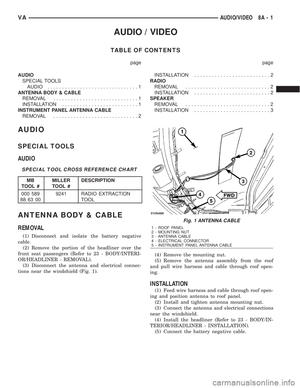
(3) Disconnect the antenna and electrical connec-
tions near the windshield (Fig. 1).(4) Remove the mounting nut.
(5) Remove the antenna assembly from the roof
and pull wire harness and cable through roof open-
ing.
INSTALLATION
(1) Feed wire harness and cable through roof open-
ing and position antenna to roof panel.
(2) Install and tighten antenna mounting nut.
(3) Connect the antenna and electrical connections
near the windshield.
(4) Install the headliner (Refer to 23 - BODY/IN-
TERIOR/HEADLINER - INSTALLATION).
(5) Connect the battery negative cable.
Fig. 1 ANTENNA CABLE
1 - ROOF PANEL
2 - MOUNTING NUT
3 - ANTENNA CABLE
4 - ELECTRICAL CONNECTOR
5 - INSTRUMENT PANEL ANTENNA CABLE
VAAUDIO/VIDEO 8A - 1
Page 851 of 2305
INSTRUMENT PANEL
ANTENNA CABLE
REMOVAL
(1) Disconnect and isolate the battery negative
cable.
(2) Remove the A-pillar trim (Refer to 23 - BODY/
INTERIOR/A-PILLAR TRIM - REMOVAL).
(3) Remove the portion of the headliner over the
front seat passengers (Refer to 23 - BODY/INTERI-
OR/HEADLINER - REMOVAL).
(4) Disconnect the antenna and electrical connec-
tions near the windshield.
(5) Remove the glove box (Refer to 23 - BODY/IN-
STRUMENT PANEL/GLOVE BOX - REMOVAL).
(6) Remove the radio (Refer to 8 - ELECTRICAL/
AUDIO/RADIO - REMOVAL).
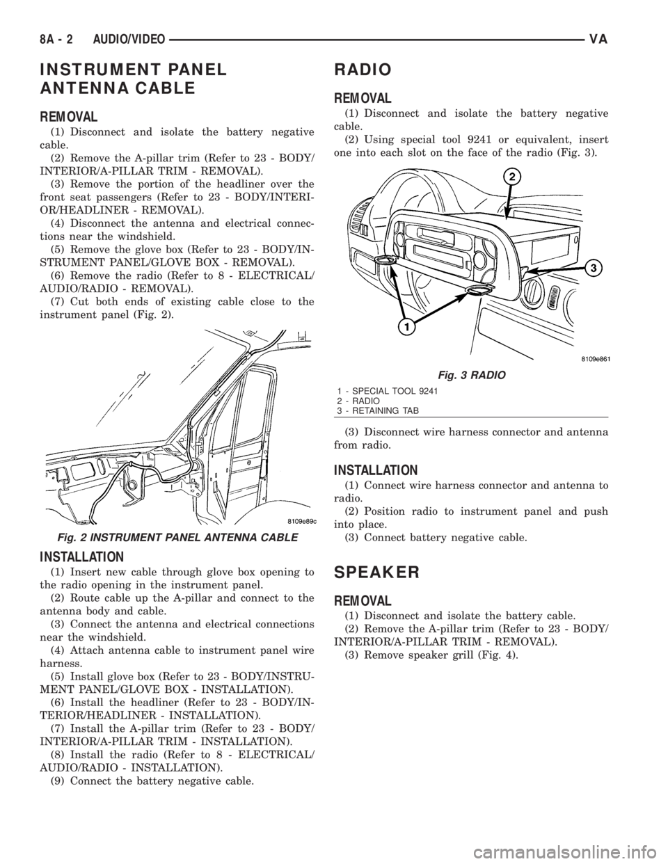
(7) Cut both ends of existing cable close to the
instrument panel (Fig. 2).
INSTALLATION
(1) Insert new cable through glove box opening to
the radio opening in the instrument panel.
(2) Route cable up the A-pillar and connect to the
antenna body and cable.
(3) Connect the antenna and electrical connections
near the windshield.
(4) Attach antenna cable to instrument panel wire
harness.
(5) Install glove box (Refer to 23 - BODY/INSTRU-
MENT PANEL/GLOVE BOX - INSTALLATION).
(6) Install the headliner (Refer to 23 - BODY/IN-
TERIOR/HEADLINER - INSTALLATION).
(7) Install the A-pillar trim (Refer to 23 - BODY/
INTERIOR/A-PILLAR TRIM - INSTALLATION).
(8) Install the radio (Refer to 8 - ELECTRICAL/
AUDIO/RADIO - INSTALLATION).
(9) Connect the battery negative cable.
RADIO
REMOVAL
(1) Disconnect and isolate the battery negative
cable.
(2) Using special tool 9241 or equivalent, insert
one into each slot on the face of the radio (Fig. 3).
(3) Disconnect wire harness connector and antenna
from radio.
INSTALLATION
(1) Connect wire harness connector and antenna to
radio.
(2) Position radio to instrument panel and push
into place.
(3) Connect battery negative cable.
SPEAKER
REMOVAL
(1) Disconnect and isolate the battery cable.
(2) Remove the A-pillar trim (Refer to 23 - BODY/
INTERIOR/A-PILLAR TRIM - REMOVAL).
(3) Remove speaker grill (Fig. 4).
Fig. 2 INSTRUMENT PANEL ANTENNA CABLE
Fig. 3 RADIO
1 - SPECIAL TOOL 9241
2 - RADIO
3 - RETAINING TAB
8A - 2 AUDIO/VIDEOVA
Page 852 of 2305
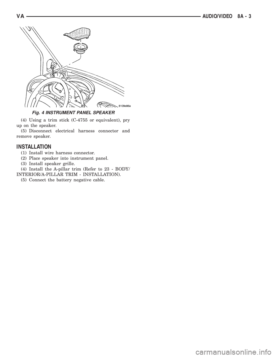
(4) Using a trim stick (C-4755 or equivalent), pry
up on the speaker.
(5) Disconnect electrical harness connector and
remove speaker.
INSTALLATION
(1) Install wire harness connector.
(2) Place speaker into instrument panel.
(3) Install speaker grille.
(4) Install the A-pillar trim (Refer to 23 - BODY/
INTERIOR/A-PILLAR TRIM - INSTALLATION).
(5) Connect the battery negative cable.
Fig. 4 INSTRUMENT PANEL SPEAKER
VAAUDIO/VIDEO 8A - 3
Page 1080 of 2305
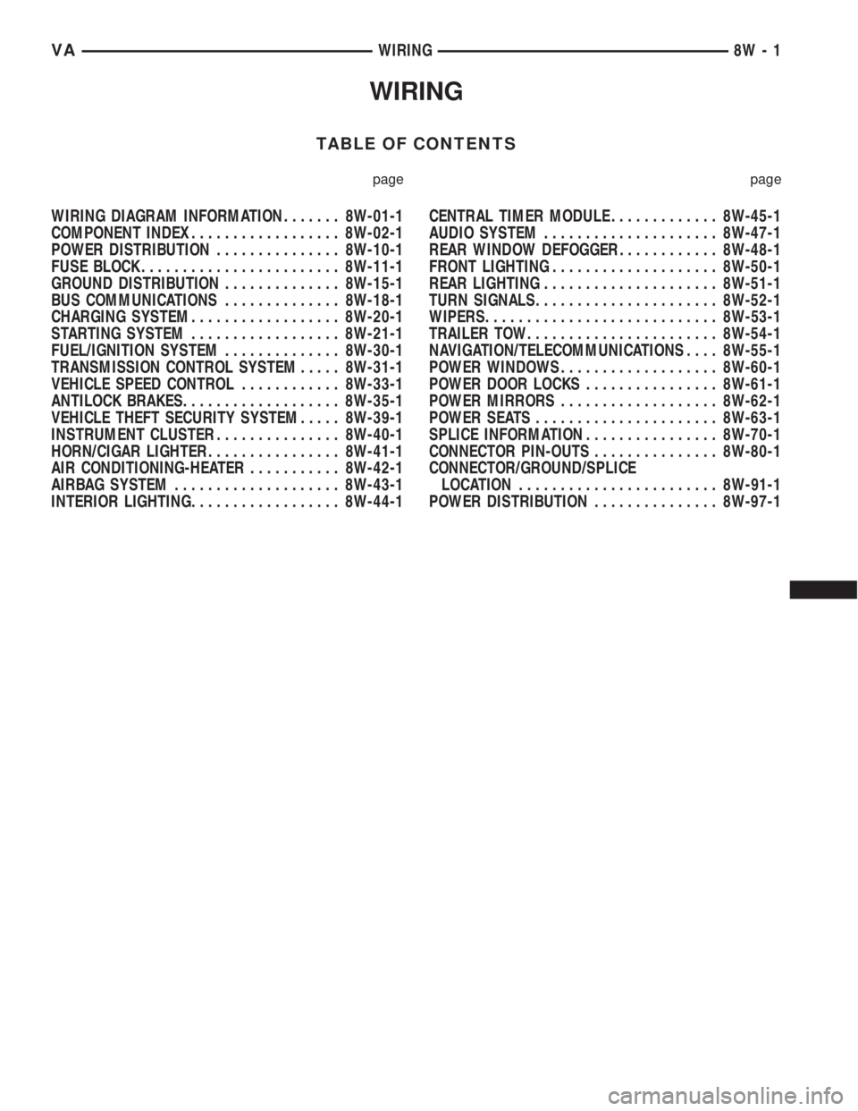
WIRING
TABLE OF CONTENTS
page page
WIRING DIAGRAM INFORMATION....... 8W-01-1
COMPONENT INDEX.................. 8W-02-1
POWER DISTRIBUTION............... 8W-10-1
FUSE BLOCK........................ 8W-11-1
GROUND DISTRIBUTION.............. 8W-15-1
BUS COMMUNICATIONS.............. 8W-18-1
CHARGING SYSTEM.................. 8W-20-1
STARTING SYSTEM.................. 8W-21-1
FUEL/IGNITION SYSTEM.............. 8W-30-1
TRANSMISSION CONTROL SYSTEM..... 8W-31-1
VEHICLE SPEED CONTROL............ 8W-33-1
ANTILOCK BRAKES................... 8W-35-1
VEHICLE THEFT SECURITY SYSTEM..... 8W-39-1
INSTRUMENT CLUSTER............... 8W-40-1
HORN/CIGAR LIGHTER................ 8W-41-1
AIR CONDITIONING-HEATER........... 8W-42-1
AIRBAG SYSTEM.................... 8W-43-1
INTERIOR LIGHTING.................. 8W-44-1CENTRAL TIMER MODULE............. 8W-45-1
AUDIO SYSTEM..................... 8W-47-1
REAR WINDOW DEFOGGER............ 8W-48-1
FRONT LIGHTING.................... 8W-50-1
REAR LIGHTING..................... 8W-51-1
TURN SIGNALS...................... 8W-52-1
WIPERS............................ 8W-53-1
TRAILER TOW....................... 8W-54-1
NAVIGATION/TELECOMMUNICATIONS.... 8W-55-1
POWER WINDOWS................... 8W-60-1
POWER DOOR LOCKS................ 8W-61-1
POWER MIRRORS................... 8W-62-1
POWER SEATS...................... 8W-63-1
SPLICE INFORMATION................ 8W-70-1
CONNECTOR PIN-OUTS............... 8W-80-1
CONNECTOR/GROUND/SPLICE
LOCATION........................ 8W-91-1
POWER DISTRIBUTION............... 8W-97-1 VAWIRING 8W - 1
Page 1340 of 2305
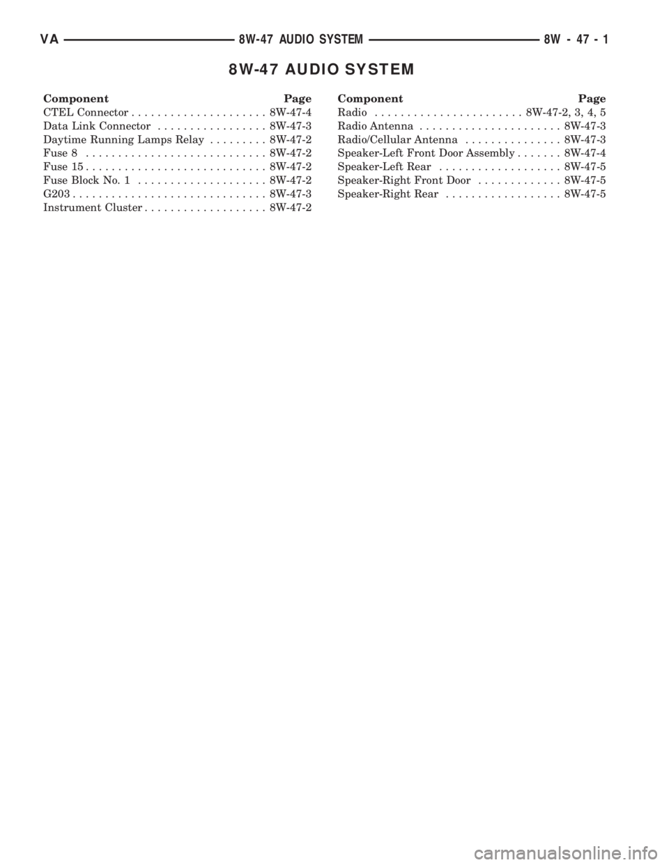
8W-47 AUDIO SYSTEM
Component Page
CTEL Connector..................... 8W-47-4
Data Link Connector................. 8W-47-3
Daytime Running Lamps Relay......... 8W-47-2
Fuse 8............................ 8W-47-2
Fuse 15............................ 8W-47-2
Fuse Block No. 1.................... 8W-47-2
G203.............................. 8W-47-3
Instrument Cluster................... 8W-47-2Component Page
Radio....................... 8W-47-2, 3, 4, 5
Radio Antenna...................... 8W-47-3
Radio/Cellular Antenna............... 8W-47-3
Speaker-Left Front Door Assembly....... 8W-47-4
Speaker-Left Rear................... 8W-47-5
Speaker-Right Front Door............. 8W-47-5
Speaker-Right Rear.................. 8W-47-5
VA8W-47 AUDIO SYSTEM 8W - 47 - 1
Page 2002 of 2305
INSTRUMENT PANEL ASSEM-
BLY
REMOVAL
WARNING: ON VEHICLES EQUIPPED WITH AIR-
BAGS, DISABLE THE AIRBAG SYSTEM BEFORE
ATTEMPTING ANY STEERING WHEEL, STEERING
COLUMN, SEAT BELT TENSIONER, OR INSTRU-
MENT PANEL COMPONENT DIAGNOSIS OR SER-
VICE. DISCONNECT AND ISOLATE THE BATTERY
NEGATIVE (GROUND) CABLE, THEN WAIT TWO
MINUTES FOR THE AIRBAG SYSTEM CAPACITOR
TO DISCHARGE BEFORE PERFORMING FURTHER
DIAGNOSIS OR SERVICE. THIS IS THE ONLY SURE
WAY TO DISABLE THE AIRBAG SYSTEM. FAILURE
TO TAKE THE PROPER PRECAUTIONS COULD
RESULT IN ACCIDENTAL AIRBAG DEPLOYMENT
AND POSSIBLE PERSONAL INJURY.
²WHEN REMOVING A DEPLOYED AIRBAG, RUB-
BER GLOVES, EYE PROTECTION, AND A LONG-
SLEEVED SHIRT SHOULD BE WORN. THERE MAY
BE DEPOSITS ON THE AIRBAG UNIT AND OTHER
INTERIOR SURFACES. IN LARGE DOSES, THESE
DEPOSITS MAY CAUSE IRRITATION TO THE SKIN
AND EYES.
²USE EXTREME CARE TO PREVENT ANY FOR-
EIGN MATERIAL FROM ENTERING THE PASSEN-
GER AIRBAG, OR BECOMING ENTRAPPED
BETWEEN THE PASSENGER AIRBAG CUSHION
AND THE PASSENGER AIRBAG DOOR. FAILURE TO
OBSERVE THIS WARNING COULD RESULT IN
OCCUPANT INJURIES UPON AIRBAG DEPLOY-
MENT.
²THE PASSENGER AIRBAG DOOR MUST
NEVER BE PAINTED. REPLACEMENT PASSENGER
AIRBAGS ARE SERVICED WITH DOORS IN THE
ORIGINAL COLORS. PAINT MAY CHANGE THE WAY
IN WHICH THE MATERIAL OF THE AIRBAG DOOR
RESPONDS TO AN AIRBAG DEPLOYMENT. FAIL-
URE TO OBSERVE THIS WARNING COULD RESULT
IN OCCUPANT INJURIES UPON AIRBAG DEPLOY-
MENT.
(1) Disconnect and isolate the battery negative
cable.
(2) Remove radio. (Refer to 8 - ELECTRICAL/AU-
DIO/RADIO - REMOVAL)
(3) Remove glove compartment. (Refer to 23 -
BODY/INSTRUMENT PANEL/GLOVE BOX -
REMOVAL)
(4) Remove cup holder. (Refer to 23 - BODY/IN-
STRUMENT PANEL/CUP HOLDER - REMOVAL)
(5) Remove instrument cluster. (Refer to 8 - ELEC-
TRICAL/INSTRUMENT CLUSTER - REMOVAL)(6) Remove passenger airbag. (Refer to 8 - ELEC-
TRICAL/RESTRAINTS/PASSENGER AIRBAG -
REMOVAL)
(7) Remove right and left speakers. (Refer to 8 -
ELECTRICAL/AUDIO/SPEAKER - REMOVAL)
(8) Remove center bezel. (Refer to 23 - BODY/IN-
STRUMENT PANEL/INSTRUMENT PANEL CEN-
TER BEZEL - REMOVAL)
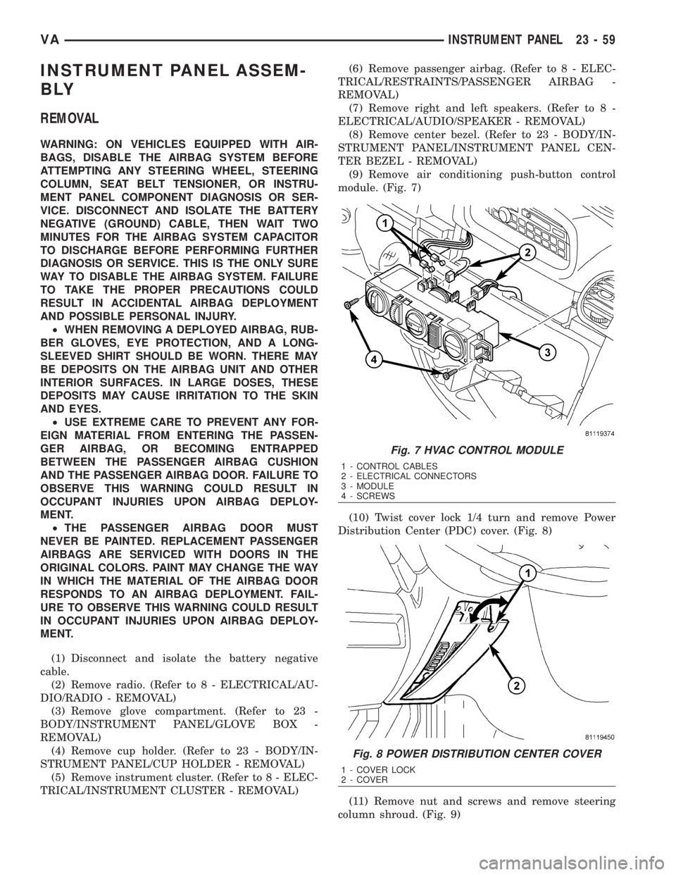
(9) Remove air conditioning push-button control
module. (Fig. 7)
(10) Twist cover lock 1/4 turn and remove Power
Distribution Center (PDC) cover. (Fig. 8)
(11) Remove nut and screws and remove steering
column shroud. (Fig. 9)
Fig. 7 HVAC CONTROL MODULE
1 - CONTROL CABLES
2 - ELECTRICAL CONNECTORS
3 - MODULE
4 - SCREWS
Fig. 8 POWER DISTRIBUTION CENTER COVER
1 - COVER LOCK
2 - COVER
VAINSTRUMENT PANEL 23 - 59
Page 2007 of 2305
(9) Install instrument panel top cover and screws.
(Fig. 15)
(10) Install right outer and inner air nozzles. (Fig.
13)
(11) Install right side cover and screws.
(12) Wrap protective mat around connectors
behind instrument cluster.
(13) Install left outer and inner air nozzles.
(14) Install left side cover and screws.
(15) Install passenger side air nozzle cover and
bracket and install the screws. (Fig. 12)
(16) Position Power Distribution Center (PDC) in
vehicle and connect electrical connectors. (Fig. 11)
(17) Install PDC and install bolt and nut. (Fig. 10)
(18) Install PDC ground cable and nut.
(19) Install steering column shroud and install the
two screws and one nut. (Fig. 9)
(20) Install PDC cover and twist lock 1/4 turn to
secure in place. (Fig. 8)
(21) Connect electrical connectors and cables to air
conditioning push-button module and install. (Fig. 7)
(22) Install center bezel. (Refer to 23 - BODY/IN-
STRUMENT PANEL/INSTRUMENT PANEL CEN-
TER BEZEL - INSTALLATION)
(23) Install left and right speakers. (Refer to 8 -
ELECTRICAL/AUDIO/SPEAKER - INSTALLATION)
(24) Install passenger airbag. (Refer to 8 - ELEC-
TRICAL/RESTRAINTS/PASSENGER AIRBAG -
INSTALLATION)
(25) Install instrument cluster. (Refer to 8 - ELEC-
TRICAL/INSTRUMENT CLUSTER - INSTALLA-
TION)
(26) Install cup holder. (Refer to 23 - BODY/IN-
STRUMENT PANEL/CUP HOLDER - INSTALLA-
TION)
(27) Install glove compartment. (Refer to 23 -
BODY/INSTRUMENT PANEL/GLOVE BOX -
INSTALLATION)
(28) Install radio. (Refer to 8 - ELECTRICAL/AU-
DIO/RADIO - INSTALLATION)
(29) Connect battery negative cable.
TOP COVER - CLUSTER
REMOVAL
WARNING: ON VEHICLES EQUIPPED WITH AIR-
BAGS, DISABLE THE AIRBAG SYSTEM BEFORE
ATTEMPTING ANY STEERING WHEEL, STEERING
COLUMN, SEAT BELT TENSIONER, OR INSTRU-
MENT PANEL COMPONENT DIAGNOSIS OR SER-
VICE. DISCONNECT AND ISOLATE THE BATTERY
NEGATIVE (GROUND) CABLE, THEN WAIT TWO
MINUTES FOR THE AIRBAG SYSTEM CAPACITOR
TO DISCHARGE BEFORE PERFORMING FURTHER
DIAGNOSIS OR SERVICE. THIS IS THE ONLY SURE
WAY TO DISABLE THE AIRBAG SYSTEM. FAILURETO TAKE THE PROPER PRECAUTIONS COULD
RESULT IN ACCIDENTAL AIRBAG DEPLOYMENT
AND POSSIBLE PERSONAL INJURY.
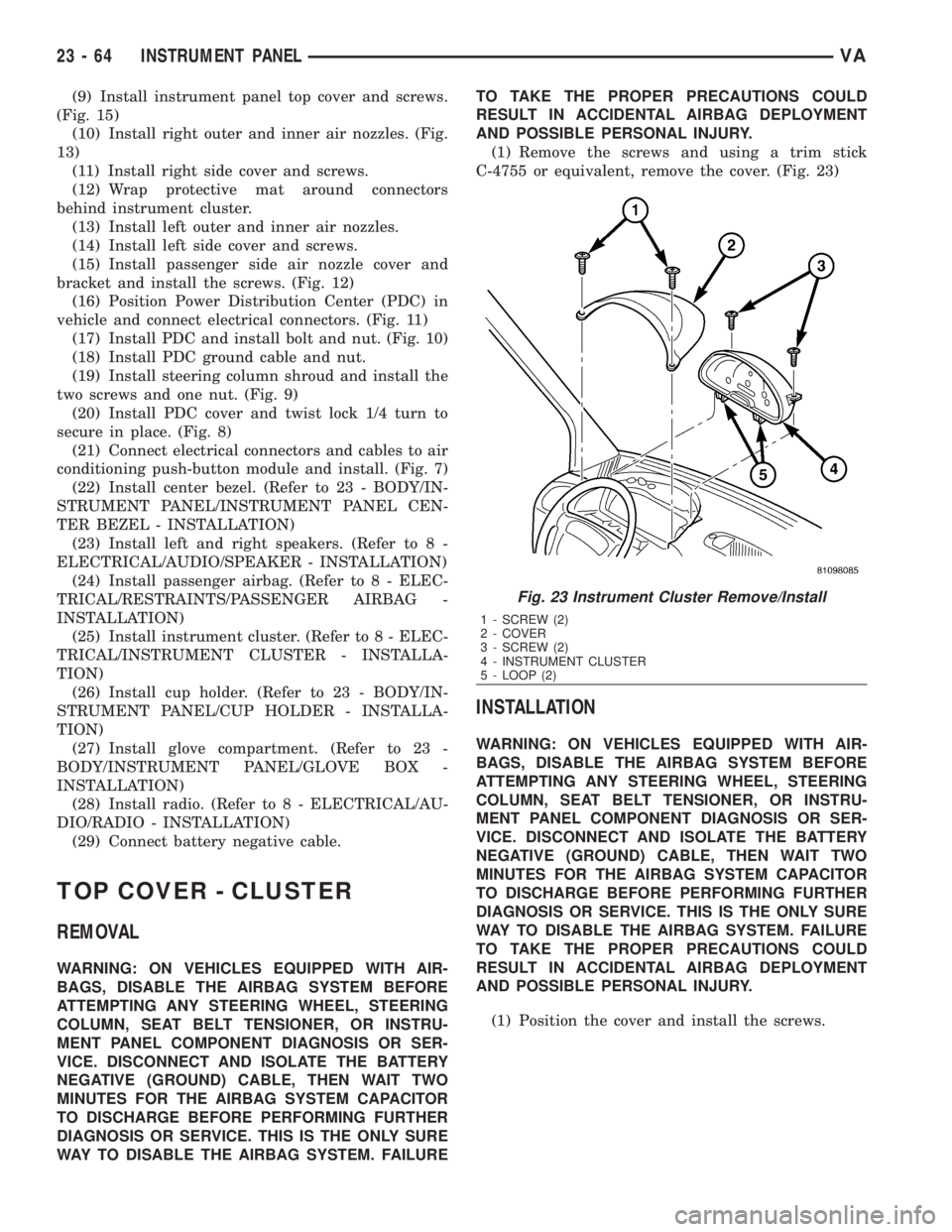
(1) Remove the screws and using a trim stick
C-4755 or equivalent, remove the cover. (Fig. 23)
INSTALLATION
WARNING: ON VEHICLES EQUIPPED WITH AIR-
BAGS, DISABLE THE AIRBAG SYSTEM BEFORE
ATTEMPTING ANY STEERING WHEEL, STEERING
COLUMN, SEAT BELT TENSIONER, OR INSTRU-
MENT PANEL COMPONENT DIAGNOSIS OR SER-
VICE. DISCONNECT AND ISOLATE THE BATTERY
NEGATIVE (GROUND) CABLE, THEN WAIT TWO
MINUTES FOR THE AIRBAG SYSTEM CAPACITOR
TO DISCHARGE BEFORE PERFORMING FURTHER
DIAGNOSIS OR SERVICE. THIS IS THE ONLY SURE
WAY TO DISABLE THE AIRBAG SYSTEM. FAILURE
TO TAKE THE PROPER PRECAUTIONS COULD
RESULT IN ACCIDENTAL AIRBAG DEPLOYMENT
AND POSSIBLE PERSONAL INJURY.
(1) Position the cover and install the screws.
Fig. 23 Instrument Cluster Remove/Install
1 - SCREW (2)
2 - COVER
3 - SCREW (2)
4 - INSTRUMENT CLUSTER
5 - LOOP (2)
23 - 64 INSTRUMENT PANELVA