2006 MERCEDES-BENZ SPRINTER oil dipstick
[x] Cancel search: oil dipstickPage 838 of 2305

Operate tester pump to apply 103.4 kPa (15 psi)
pressure to system. If hoses enlarge excessively or
bulges while testing, replace as necessary. Observe
gauge pointer and determine condition of cooling sys-
tem according to following criteria:
Holds Steady:If pointer remains steady for two
minutes, serious coolant leaks are not present in sys-
tem. However, there could be an internal leak that
does not appear with normal system test pressure. If
it is certain that coolant is being lost and leaks can-
not be detected, inspect for interior leakage or per-
form Internal Leakage Test.
Drops Slowly:Indicates a small leak or seepage
is occurring. Examine all connections for seepage or
slight leakage with a flashlight. Inspect radiator,
hoses, gasket edges and heater. Seal small leak holes
with a Sealer Lubricant (or equivalent). Repair leak
holes and inspect system again with pressure
applied.
Drops Quickly:Indicates that serious leakage is
occurring. Examine system for external leakage. If
leaks are not visible, inspect for internal leakage.
Large radiator leak holes should be repaired by a
reputable radiator repair shop.
INTERNAL LEAKAGE INSPECTION
Remove engine oil pan drain plug and drain a
small amount of engine oil. If coolant is present in
the pan, it will drain first because it is heavier than
oil. An alternative method is to operate engine for a
short period to churn the oil. After this is done,
remove engine dipstick and inspect for water glob-ules. Also inspect transmission dipstick for water
globules and transmission fluid cooler for leakage.
WARNING: WITH RADIATOR PRESSURE TESTER
TOOL INSTALLED ON RADIATOR, DO NOT ALLOW
PRESSURE TO EXCEED 110 KPA (20 PSI). PRES-
SURE WILL BUILD UP QUICKLY IF A COMBUSTION
LEAK IS PRESENT. TO RELEASE PRESSURE,
ROCK TESTER FROM SIDE TO SIDE. WHEN
REMOVING TESTER, DO NOT TURN TESTER MORE
THAN 1/2 TURN IF SYSTEM IS UNDER PRESSURE.
Operate engine without pressure cap on coolant
container until thermostat opens. Attach a Pressure
Tester to container. If pressure builds up quickly it
indicates a combustion leak exists. This is usually
the result of a cylinder head gasket leak or crack in
engine. Repair as necessary.
If there is not an immediate pressure increase,
pump the Pressure Tester. Do this until indicated
pressure is within system range of 110 kPa (16 psi).
Fluctuation of gauge pointer indicates compression or
combustion leakage into cooling system.
Because the vehicle is equipped with a catalytic
converter,do notremove spark plug cables or short
out cylinders to isolate compression leak.
If the needle on dial of pressure tester does not
fluctuate, race engine a few times to check for an
abnormal amount of coolant or steam. This would be
emitting from exhaust pipe. Coolant or steam from
exhaust pipe may indicate a faulty cylinder head gas-
ket, cracked engine cylinder block or cylinder head.
A convenient check for exhaust gas leakage into
cooling system is provided by a commercially avail-
able Block Leak Check tool. Follow manufacturers
instructions when using this product.
COMBUSTION LEAKAGE TEST - WITHOUT PRES-
SURE TESTER
DO NOT WASTE reusable coolant. If solution is
clean, drain coolant into a clean and suitably marked
container for reuse.
WARNING: Do not remove cylinder block drain
plugs or loosen radiator drain with system hot and
under pressure. serious burns from coolant can
occur.
Drain sufficient coolant to allow thermostat
removal.
Remove accessory drive belt.
Add coolant to pressure container to bring level to
within 6.3 mm (1/4 in) of top of thermostat housing.
CAUTION: Avoid overheating. Do not operate
engine for an excessive period of time. Open drain-
cock immediately after test to eliminate boil over.
Fig. 2 PRESSURE TESTING
1 - PRESSURE RESERVOIR CAP
2 - PRESSURE RESERVOIR
3 - PRESSURE TESTER
VAENGINE 7 - 11
Page 939 of 2305

through the fuel level sense circuit. The fuel level
sensor is a potentiometer that changes resistance
according to the fuel level. As the fuel level
decreases, the resistance through the fuel level sen-
sor increases. The instrument cluster applies a fuel
tank characteristic curve and fuel tank reserve valve
setting to the fuel level sensor input, which must be
configured when the cluster is initialized. These
characteristics determine the algorithm the cluster
uses to display the fuel level data on the fuel gauge
and the control for the low fuel warning indicator.
The fuel level sensor and the fuel level sense circuit
to the instrument cluster can be diagnosed using con-
ventional diagnostic tools and methods. For proper
diagnosis of the instrument cluster circuitry that con-
trols the fuel gauge, a diagnostic scan tool is
required. Refer to the appropriate diagnostic infor-
mation.
LOW OIL LEVEL INDICATOR
DESCRIPTION
A low oil level indicator is standard equipment on
all instrument clusters. The low oil level indicator is
located near the lower edge of the instrument cluster,
to the left of the multi-function indicator display. The
low oil level indicator consists of the International
Control and Display Symbol icon for ªEngine Oilº
imprinted within a rectangular cutout in the opaque
layer of the instrument cluster overlay. The dark
outer layer of the overlay prevents the indicator from
being clearly visible when it is not illuminated. A red
Light Emitting Diode (LED) behind the cutout in the
opaque layer of the overlay causes the icon to appear
silhouetted against a red field through the translu-
cent outer layer of the overlay when the indicator is
illuminated from behind by the LED, which is sol-
dered onto the instrument cluster electronic circuit
board. The low oil level indicator is serviced as a unit
with the instrument cluster.
OPERATION
The low oil level indicator gives an indication to
the vehicle operator when the engine oil level is low.
This indicator is controlled by a transistor on the
instrument cluster electronic circuit board based
upon cluster programming and electronic messages
received by the cluster from the Engine Control Mod-
ule (ECM) over the Controller Area Network (CAN)
data bus. The low oil level indicator Light Emitting
Diode (LED) is completely controlled by the instru-
ment cluster logic circuit, and that logic will only
allow this indicator to operate when the instrument
cluster detects that the ignition switch is in the On
position. Therefore, the LED will always be off when
the ignition switch is in any position except On. The
LED only illuminates when it is provided a path toground by the instrument cluster transistor. The
instrument cluster will turn on the low oil level indi-
cator for the following reasons:
²Bulb Test- Each time the ignition switch is
turned to the On position the low oil level indicator
is illuminated for about two seconds as a bulb test.
²Engine Oil Level Low Message- Once the
engine has been started, each time the cluster
receives a message from the ECM indicating that the
engine oil level is at or near the ªMinimumº mark on
the dipstick, the low oil level indicator is illuminated.
The indicator remains illuminated briefly at first, but
will remain illuminated for longer periods as subse-
quent messages indicate that the oil level has
dropped further. Eventually, the indicator will
remain illuminated solid until the engine oil level is
corrected, or until the ignition switch is turned to the
Off position, whichever occurs first.
The instrument cluster also supplements the oil
level indicator by displaying an engine oil icon along
with alpha-numeric messages in the multi-function
indicator Liquid Crystal Display (LCD) advising the
vehicle operator how much oil is required to correct
the engine oil level, and when the ªMaximumº engine
oil level has been exceeded. See the owner's manual
in the vehicle glove box for more information on this
feature.
The ECM continually monitors the engine oil level
and temperature sensor to determine the engine oil
level. The ECM then sends the proper engine oil
level messages to the instrument cluster. If the
instrument cluster turns on the indicator after the
bulb test, even after the engine oil level is sufficient,
it may indicate that the engine or the engine oiling
system requires service. For proper diagnosis of the
engine oil level and temperature sensor, the ECM,
the CAN data bus, or the electronic message inputs
to the instrument cluster that control the low oil
level indicator, a diagnostic scan tool is required.
Refer to the appropriate diagnostic information.
MAINTENANCE INDICATOR
DESCRIPTION
An Active Service SYSTem (ASSYST) engine oil
maintenance indicator is optional equipment on all
instrument clusters. In vehicles so equipped, a sec-
ond, dedicated ASSYST microprocessor is integral to
the cluster electronic circuit board. The ASSYST indi-
cations are displayed and can be toggled with the
clock indication on the right side of the multi-func-
tion indicator Liquid Crystal Display (LCD) located
near the lower edge of the instrument cluster,
directly below the speedometer. The ASSYST displays
include numeric values combined with several icons
to indicate actual engine oil level, and reminders in
time (days) or distance (miles or kilometers) until the
8J - 20 INSTRUMENT CLUSTERVA
Page 1830 of 2305

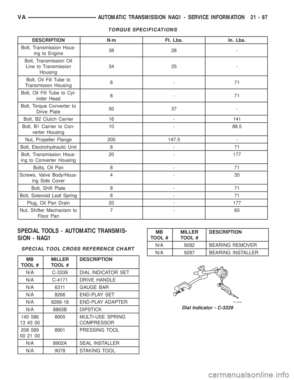
TORQUE SPECIFICATIONS
DESCRIPTION N´m Ft. Lbs. In. Lbs.
Bolt, Transmission Hous-
ing to Engine38 28 -
Bolt, Transmission Oil
Line to Transmission
Housing34 25 -
Bolt, Oil Fill Tube to
Transmisson Housing8-71
Bolt, Oil Fill Tube to Cyl-
inder Head8-71
Bolt, Torque Converter to
Drive Plate50 37 -
Bolt, B2 Clutch Carrier 16 - 141
Bolt, B1 Carrier to Con-
verter Housing10 - 88.5
Nut, Propeller Flange 200 147.5 -
Bolt, Electrohydraulic Unit 8 - 71
Bolt, Transmission Hous-
ing to Converter Housing20 - 177
Bolts, Oil Pan 8 - 71
Screws, Valve Body/Hous-
ing Side Cover4-35
Bolt, Shift Plate 8 - 71
Bolt, Solenoid Leaf Spring 8 - 71
Plug, Oil Pan Drain 20 - 177
Nut, Shifter Mechanism to
Floor Pan7-65
SPECIAL TOOLS - AUTOMATIC TRANSMIS-
SION - NAG1
SPECIAL TOOL CROSS REFERENCE CHART
MB
TOOL #MILLER
TOOL #DESCRIPTION
N/A C-3339 DIAL INDICATOR SET
N/A C-4171 DRIVE HANDLE
N/A 6311 GAUGE BAR
N/A 8266 END-PLAY SET
N/A 8266-18 END-PLAY ADAPTER
N/A 8863B DIPSTICK
140 586
13 43 008900 MULTI-USE SPRING
COMPRESSOR
208 589
00 21 008901 PRESSING TOOL
N/A 8902A SEAL INSTALLER
N/A 9078 STAKING TOOL
MB
TOOL #MILLER
TOOL #DESCRIPTION
N/A 9082 BEARING REMOVER
N/A 9287 BEARING INSTALLER
Dial Indicator - C-3339
VAAUTOMATIC TRANSMISSION NAG1 - SERVICE INFORMATION 21 - 87
Page 1875 of 2305

CAUSES OF BURNT FLUID
Burnt, discolored fluid is a result of overheating
which has three primary causes.
1. Internal clutch slippage, usually caused by low
line pressure, inadequate clutch apply pressure, or
clutch seal failure.
2. A result of restricted fluid flow through the
main and/or auxiliary cooler. This condition is usu-
ally the result of a faulty or improperly installed
drainback valve, a damaged oil cooler, or severe
restrictions in the coolers and lines caused by debris
or kinked lines.
3. Heavy duty operation with a vehicle not prop-
erly equipped for this type of operation. Trailer tow-
ing or similar high load operation will overheat the
transmission fluid if the vehicle is improperly
equipped. Such vehicles should have an auxiliary
transmission fluid cooler, a heavy duty cooling sys-
tem, and the engine/axle ratio combination needed to
handle heavy loads.
FLUID CONTAMINATION
Transmission fluid contamination is generally a
result of:
²adding incorrect fluid
²failure to clean dipstick and fill tube when
checking level
²engine coolant entering the fluid
²internal failure that generates debris
²overheat that generates sludge (fluid break-
down)
²failure to replace contaminated converter after
repair
The use of non-recommended fluids can result in
transmission failure. The usual results are erratic
shifts, slippage, abnormal wear and eventual failure
due to fluid breakdown and sludge formation. Avoid
this condition by using recommended fluids only.
The dipstick cap and fill tube should be wiped
clean before checking fluid level. Dirt, grease and
other foreign material on the cap and tube could fall
into the tube if not removed beforehand. Take the
time to wipe the cap and tube clean before withdraw-
ing the dipstick.
Engine coolant in the transmission fluid is gener-
ally caused by a cooler malfunction. The only remedy
is to replace the radiator as the cooler in the radiator
is not a serviceable part. If coolant has circulated
through the transmission, an overhaul is necessary.
The torque converter should be replaced whenever
a failure generates sludge and debris. This is neces-
sary because normal converter flushing procedures
will not remove all contaminants.
STANDARD PROCEDURE
CHECK OIL LEVEL
(1) Verify that the vehicle is parked on a level sur-
face.
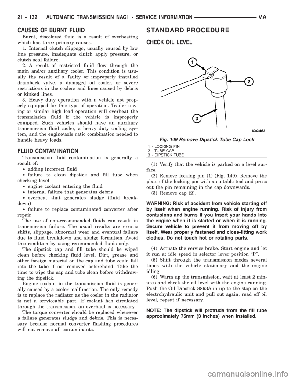
(2) Remove locking pin (1) (Fig. 149). Remove the
plate of the locking pin with a suitable tool and press
out the pin remaining in the cap downwards.
(3) Remove cap (2).
WARNING: Risk of accident from vehicle starting off
by itself when engine running. Risk of injury from
contusions and burns if you insert your hands into
the engine when it is started or when it is running.
Secure vehicle to prevent it from moving off by
itself. Wear properly fastened and close-fitting work
clothes. Do not touch hot or rotating parts.
(4) Actuate the service brake. Start engine and let
it run at idle speed in selector lever position ªPº.
(5) Shift through the transmission modes several
times with the vehicle stationary and the engine
idling
(6) Warm up the transmission, wait at least 2 min-
utes and check the oil level with the engine running.
Push the Oil Dipstick 8863A in up to the stop on the
electrohydraulic unit and pull out again, read off oil
level, repeat if necessary.
NOTE: The dipstick will protrude from the fill tube
approximately 75mm (3 inches) when installed.
Fig. 149 Remove Dipstick Tube Cap Lock
1 - LOCKING PIN
2 - TUBE CAP
3 - DIPSTICK TUBE
21 - 132 AUTOMATIC TRANSMISSION NAG1 - SERVICE INFORMATIONVA
Page 1876 of 2305

(7) Check transmission oil temperature.
NOTE: The true transmission oil temperature can
only be read by a scan tool in REVERSE or any for-
ward gear position. (Refer to 21 - AUTOMATIC
TRANSMISSION- NAG1/TRANSMISSION TEMPERA-
TURE SENSOR/PARK-NEUTRAL SWITCH - OPERA-
TION)
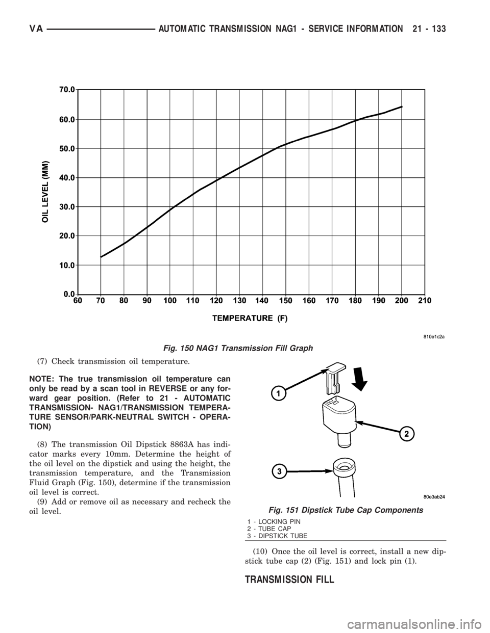
(8) The transmission Oil Dipstick 8863A has indi-
cator marks every 10mm. Determine the height of
the oil level on the dipstick and using the height, the
transmission temperature, and the Transmission
Fluid Graph (Fig. 150), determine if the transmission
oil level is correct.
(9) Add or remove oil as necessary and recheck the
oil level.
(10) Once the oil level is correct, install a new dip-
stick tube cap (2) (Fig. 151) and lock pin (1).
TRANSMISSION FILL
Fig. 150 NAG1 Transmission Fill Graph
Fig. 151 Dipstick Tube Cap Components
1 - LOCKING PIN
2 - TUBE CAP
3 - DIPSTICK TUBE
VAAUTOMATIC TRANSMISSION NAG1 - SERVICE INFORMATION 21 - 133
Page 1877 of 2305

To avoid overfilling transmission after a fluid
change or overhaul, perform the following procedure:
(1) Verify that the vehicle is parked on a level sur-
face.
(2) Remove locking pin (1) (Fig. 152). Remove the
plate of the locking pin with a suitable tool and press
out the pin remaining in the cap downwards.
(3) Remove cap (2).
(4) Add following initial quantity of required fluid
(Refer to LUBRICATION & MAINTENANCE/FLUID
TYPES - DESCRIPTION) to transmission:
(a) If only fluid and filter were changed, add7.4
L (14.8 pts.)of transmission fluid to transmission.
(b) If transmission was completely overhauled,
torque converter was replaced or drained, and
cooler was flushed, add7.7 L (16.3 pts.)of trans-
mission fluid to transmission.
(5) Check the transmission fluid (Refer to 21 -
TRANSMISSION/AUTOMATIC - NAG1/FLUID AND
FLUID - STANDARD PROCEDURE - CHECK OIL
LEVEL) and adjust as required.
FLUID / FILTER SERVICE
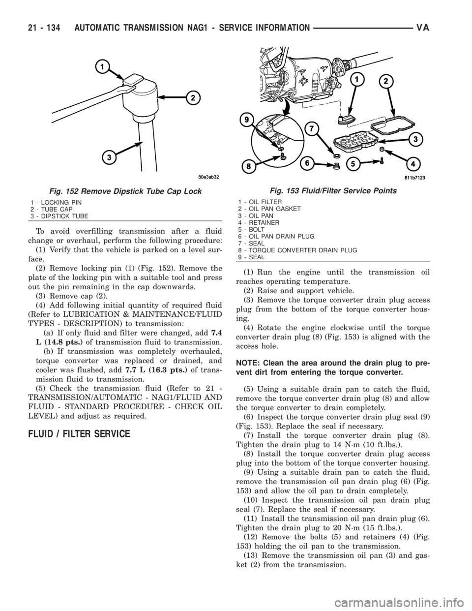
(1) Run the engine until the transmission oil
reaches operating temperature.
(2) Raise and support vehicle.
(3) Remove the torque converter drain plug access
plug from the bottom of the torque converter hous-
ing.
(4) Rotate the engine clockwise until the torque
converter drain plug (8) (Fig. 153) is aligned with the
access hole.
NOTE: Clean the area around the drain plug to pre-
vent dirt from entering the torque converter.
(5) Using a suitable drain pan to catch the fluid,
remove the torque converter drain plug (8) and allow
the torque converter to drain completely.
(6) Inspect the torque converter drain plug seal (9)
(Fig. 153). Replace the seal if necessary.
(7) Install the torque converter drain plug (8).
Tighten the drain plug to 14 N´m (10 ft.lbs.).
(8) Install the torque converter drain plug access
plug into the bottom of the torque converter housing.
(9) Using a suitable drain pan to catch the fluid,
remove the transmission oil pan drain plug (6) (Fig.
153) and allow the oil pan to drain completely.
(10) Inspect the transmission oil pan drain plug
seal (7). Replace the seal if necessary.
(11) Install the transmission oil pan drain plug (6).
Tighten the drain plug to 20 N´m (15 ft.lbs.).
(12) Remove the bolts (5) and retainers (4) (Fig.
153) holding the oil pan to the transmission.
(13) Remove the transmission oil pan (3) and gas-
ket (2) from the transmission.
Fig. 152 Remove Dipstick Tube Cap Lock
1 - LOCKING PIN
2 - TUBE CAP
3 - DIPSTICK TUBE
Fig. 153 Fluid/Filter Service Points
1 - OIL FILTER
2 - OIL PAN GASKET
3 - OIL PAN
4 - RETAINER
5 - BOLT
6 - OIL PAN DRAIN PLUG
7 - SEAL
8 - TORQUE CONVERTER DRAIN PLUG
9 - SEAL
21 - 134 AUTOMATIC TRANSMISSION NAG1 - SERVICE INFORMATIONVA