Page 704 of 2305
GROUP TAB LOCATOR
Introduction
0Lubrication & Maintenance
2Suspension
3Differential & Driveline
5Brakes
7Cooling
8AAudio/Video
8BChime/Buzzer
8EElectronic Control Modules
8FEngine Systems
8GHeated Systems
8HHorn
8IIgnition Control
8JInstrument Cluster
8LLamps
8NPower Systems
8ORestraints
8PSpeed Control
8QVehicle Theft Security
8RWipers/Washers
8WWiring
9Engine
11Exhaust System
13Frame & Bumpers
14Fuel System
19Steering
21Transmission
22Tires/Wheels
23Body
24Heating & Air Conditioning
25Emissions Control
Component and System Index
Service Manual Comment Forms (Rear of Manual)
Page 746 of 2305

DIFFERENTIAL & DRIVELINE
TABLE OF CONTENTS
page page
PROPELLER SHAFT.......................1REAR AXLE.............................12
PROPELLER SHAFT
TABLE OF CONTENTS
page page
PROPELLER SHAFT
DIAGNOSIS AND TESTING
PROPELLER SHAFT....................1
STANDARD PROCEDURE.................4
SPECIFICATIONS........................6
SPECIAL TOOLS........................6PROPELLER SHAFT
REMOVAL.............................7
INSTALLATION..........................9
CENTER BEARING
REMOVAL.............................9
INSTALLATION.........................10
PROPELLER SHAFT
DIAGNOSIS AND TESTING
PROPELLER SHAFT
PROPELLER SHAFT VIBRATION
Out-of-round tires or wheels that are out of bal-
ance, will cause a low frequency vibration.
Driveline vibration can be from loose or damaged
engine mounts.
Propeller shaft vibration increases with vehicle
speed. A vibration within a specific speed is not usu-
ally caused by a out of balanced propeller shaft.
Worn universal joints or an incorrect propeller shaft
angle, usually cause such a vibration.
VADIFFERENTIAL & DRIVELINE 3 - 1
Page 757 of 2305

REAR AXLE
TABLE OF CONTENTS
page page
REAR AXLE
DIAGNOSIS AND TESTING................12
STANDARD PROCEDURE - DRAIN AND FILL . . 13
REMOVAL.............................14
INSTALLATION.........................16
SPECIFICATIONS.......................18
SPECIAL TOOLS.......................19
SHAFT-AXLE SINGLE REAR WHEEL
REMOVAL-SINGLE REAR WHEEL..........23
INSTALLATION-SINGLE REAR WHEEL.......24
BEARING/SEAL-AXLE
REMOVAL.............................24
INSTALLATION.........................26
SHAFT-AXLE DUAL REAR WHEELS
REMOVAL-DUAL REAR WHEEL............27
INSTALLATION-DUAL REAR WHEEL........28
BEARING/SEAL-AXLE HUB
REMOVAL.............................28
INSTALLATION.........................29DIFFERENTIAL
REMOVAL.............................31
DISASSEMBLY
DISASSEMBLY-SINGLE REAR WHEEL.....32
DISASSEMBLY-DUAL REAR WHEEL.......33
ASSEMBLY
ASSEMBLY-SINGLE REAR WHEEL........34
ASSEMBLY-DUAL REAR WHEEL..........36
INSTALLATION.........................37
BEARINGS-DIFFERENTIAL CASE
REMOVAL.............................38
INSTALLATION.........................38
SEAL-PINION
REMOVAL.............................39
INSTALLATION.........................40
GEAR-PINION/RING
REMOVAL.............................41
INSTALLATION.........................42
REAR AXLE
DIAGNOSIS AND TESTING
NOTE: Axle seals, axle bearings, pinion seals and
differential cover are the only serviceble compo-
nents. If differential is damaged/noisy the axle must
be replaced.
GEAR NOISE
Axle gear noise can be caused by insufficient lubri-
cant, incorrect backlash, incorrect pinion depth, tooth
contact, worn/damaged gears, or the carrier housing
not having the proper offset and squareness.
Gear noise usually happens at a specific speed
range. The noise can also occur during a specific type
of driving condition. These conditions are accelera-
tion, deceleration, coast, or constant load.
When road testing, first warm-up the axle fluid by
driving the vehicle at least 5 miles and then acceler-
ate the vehicle to the speed range where the noise is
the greatest. Shift out-of-gear and coast through the
peak-noise range. If the noise stops or changes
greatly:
²Check for insufficient lubricant.
²Incorrect ring gear backlash.
²Gear damage.
Differential side gears and pinions can be checked
by turning the vehicle. They usually do not causenoise during straight-ahead driving when the gears
are unloaded. The side gears are loaded during vehi-
cle turns. A worn pinion shaft can also cause a snap-
ping or a knocking noise.
BEARING NOISE
The axle shaft, differential and pinion bearings can
all produce noise when worn or damaged. Bearing
noise can be either a whining, or a growling sound.
Pinion bearingshave a constant-pitch noise. This
noise changes only with vehicle speed. Pinion bearing
noise will be higher pitched because it rotates at a
faster rate. Drive the vehicle and load the differen-
tial. If bearing noise occurs, the rear pinion bearing
is the source of the noise. If the bearing noise is
heard during a coast, the front pinion bearing is the
source.
Differential bearings usually produce a low pitch
noise. Differential bearing noise is similar to pinion
bearing noise. The pitch of differential bearing noise
is also constant and varies only with vehicle speed.
Axle shaft bearingsproduce noise and vibration
when worn or damaged. The noise generally changes
when the bearings are loaded. Road test the vehicle.
Turn the vehicle sharply to the left and to the right.
This will load the bearings and change the noise
level. Where axle bearing damage is slight, the noise
is usually not noticeable at speeds above 30 mph.
3 - 12 REAR AXLEVA
Page 763 of 2305
SPECIFICATIONS
AXLE SPECIFICATIONS
DESCRIPTION SPECIFICATION
Axle Ratio 3.73, 4.11
Ring Gear Diameter 216 mm (8.5 in.)
Ring Gear Backlash 0.10-0.15 mm (0.004-
0.006 in.)
Pinion Torque to Rotate 2.5-3.0 N´m (22-26 in.
lbs.)
Differential Bearing Pre-
load0.16 mm (0.006 in.)
SRW Differential Torque
to Rotate20-40 N´m (15-30 ft.
lbs.)
TORQUE SPECIFICATIONS
DESCRIPTION N´m Ft. Lbs. In. Lbs.
Drain Plug 100 74 -
Fill Plug 100 74 -
Differential Cover Bolts 65 48 -
Ring Gear Bolts 180 133 -
Differential Bearing Cap
Bolts70 52 -
Differential Case Bolts 45 33 -
Axle Bearing Cap Bolts 72 53 -
Axle Grooved Nut 500 369 -
Axle Shaft Hub Nut 65 48 -
*Hub Inner Nut 300 221 -
Hub Outer Nut 250 184 -
*Follow service procedure for torque sequence.
3 - 18 REAR AXLEVA
Page 776 of 2305

DIFFERENTIAL
REMOVAL
(1) Remove differential fill plug.
(2) Remove differential cover and drain fluid.
(3) Remove axle shafts.
(4) Mark bearing caps and housing for installation
reference.
(5) Remove differential bearing cap bolts.
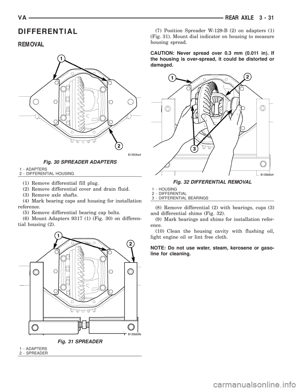
(6) Mount Adapters 9317 (1) (Fig. 30) on differen-
tial housing (2).(7) Position Spreader W-129-B (2) on adapters (1)
(Fig. 31). Mount dial indicator on housing to measure
housing spread.
CAUTION: Never spread over 0.3 mm (0.011 in). If
the housing is over-spread, it could be distorted or
damaged.
(8) Remove differential (2) with bearings, cups (3)
and differential shims (Fig. 32).
(9) Mark bearings and shims for installation refer-
ence.
(10) Clean the housing cavity with flushing oil,
light engine oil or lint free cloth.
NOTE: Do not use water, steam, kerosene or gaso-
line for cleaning.
Fig. 30 SPREADER ADAPTERS
1 - ADAPTERS
2 - DIFFERENTIAL HOUSING
Fig. 31 SPREADER
1 - ADAPTERS
2 - SPREADER
Fig. 32 DIFFERENTIAL REMOVAL
1 - HOUSING
2 - DIFFERENTIAL
3 - DIFFERENTIAL BEARINGS
VAREAR AXLE 3 - 31
Page 777 of 2305
DISASSEMBLY
DISASSEMBLY - SINGLE REAR WHEEL
(1) Remove differential cover bolts and remove
cover (Fig. 33).
(2) Remove upper differential side gear (1) and
shim (2) (Fig. 34).(3) Remove first set of differential pinion gears (1),
spherical washers and mate shaft (2) (Fig. 35).
(4) Remove second set of differential pinion gears
(2), spherical washers and mate shaft (1) (Fig. 36).
Fig. 33 DIFFERENTIAL COVER
1 - BOLTS
2 - COVER
Fig. 34 UPPER SIDE GEAR
1 - SIDE GEAR
2 - SHIM
Fig. 35 FIRST PINION GEARS
1 - PINION GEARS
2 - MATE SHAFT
Fig. 36 SECOND PINION GEAR SET
1 - MATE SHAFT
2 - PINION GEARS
3 - 32 REAR AXLEVA
Page 778 of 2305
(5) Remove lower differential side gear (1) and
shim (Fig. 37).
DISASSEMBLY - DUAL REAR WHEEL
(1) Remove differential cover bolts and remove
cover (Fig. 38).(2) Remove upper differential side gear (1) and
shim (2) (Fig. 39).
(3) Remove differential cross shaft (1) with pinion
gears (2) and spherical washers (3) (Fig. 40).
Fig. 37 LOWER SIDE GEAR
1 - SIDE GEAR
2 - DIFFERENTIAL CASE
Fig. 38 DIFFERENTIAL COVER
1 - BOLTS
2 - COVER
Fig. 39 UPPER SIDE GEAR
1 - SIDE GEAR
2 - SHIM
Fig. 40 DIFFERENTIAL PINIONS
1 - CROSS SHAFT
2 - PINION GEAR
3 - WASHER
VAREAR AXLE 3 - 33
Page 779 of 2305
(4) Remove lower differential side gear (1) and
shim (Fig. 41).
ASSEMBLY
ASSEMBLY - SINGLE REAR WHEEL
(1) Install lower differential side gear (1) and shim
(Fig. 42).(2) Install first differential pinions gears (1) with
spherical washers and mate shaft (2) (Fig. 43).
(3) Install second pinion gears (2) with spherical
washers and mate shaft (1) (Fig. 44).
Fig. 41 LOWER SIDE GEAR
1 - SIDE GEAR
2 - DIFFERENTIAL CASE
Fig. 42 LOWER SIDE GEAR
1 - SIDE GEAR
2 - DIFFERENTIAL CASE
Fig. 43 PINION GEAR SET
1 - MATE SHAFT
2 - PINION GEARS
Fig. 44 PINION GEARS
1 - PINION GEARS
2 - MATE SHAFT
3 - 34 REAR AXLEVA