2006 MERCEDES-BENZ SPRINTER key battery
[x] Cancel search: key batteryPage 15 of 2305

secured to the floor under the Driver seat and
receives power from the Fuse Block No. 1. When-
ever the ignition key is turned to the run or start
position, the ACM performs a system test. The ACM
cannot be repaired or adjusted.
The microprocessor in the ACM monitors the
internal and external airbag system electrical cir-
cuits to determine the system readiness. When a
monitored system is determine to be out of range,
the ACM will set both active and stored diagnostic
trouble codes (DTC). The ACM also contains an
energy-storage capacitor. This capacitor stores
enough electrical energy to deploy the front airbag
components for two seconds following a battery
disconnect or failure during an impact.
The Accelerometer in the ACM is used to sense
the rate of vehicle deceleration, provide verification
of the direction and severity of an impact. When the
preprogrammed conditions are met, the ACM sends
an electrical signal to deploy the appropriate front
airbag system components and a deployment noti-
fication.
To provide an accident response notification, the
ACM is hardwired to the Central Timer module
(CTM) and Engine Control Module (ECM). When a
deployment occurs the ACM provides a 50ms 10.0
volt pulse to the CTM and ECM. When the Accident
Report notification signal is received the CTM un-
locks the door locks and the ECM stalls the engine.
The Accident signal will set a DTC in the CTM and
the door locks will not work until the DTC has been
erased. The ECM will set a DTC if the Accident
Report circuit is shorted to battery voltage. The
ACM saves the deployment record and after three
deployments the ACM must be replaced. The
DRBIIItcan be used to test the Accident Report
Notification feature: select the SYSTEM TEST from
the ACM main menu. Then select the Analog Crash
Output System Test.
The ACM is hardwired to the Instrument Cluster
(MIC) to control Warning Indicator (SRS indicator).
When DTCs becomes activate, the ACM illuminates
the Warning Indicator by pulling the indicator
circuit low. The SRS indicator is the only point at
which the customer can observe symptoms of a
system malfunction.
As part of the system test the ACM illuminates
the Warning Indicator on for 4.0 second bulb test.
After the lamp check, if the indicator turns off, it
means that the ACM has checked the system and
found it to be free of discernible malfunctions.
NON-CRITICAL DTCs
If the lamp comes on and stays on for a period
longer than 4.0 seconds (about 10.0 seconds) is
usually a stored DTC (intermittent problem) in the
system.
CRITICAL DTCs
DTCs that could lead to a condition where the
safety devises may not deploy or incorrectly deploy.
In the event of such a DTC, the safety of the vehicle
occupants can no longer be guaranteed. If the lamp
remains on, there could be an active DTC in the
system. Some DTCs, Internal Module and squib
DTCs, will keep the indicator illuminated even if
the codes are no longer active.
ACM NOT CONFIGURED FOR PASSENGER
AIRBAG AND TENSIONER
If after replacing the ACM the Airbag Warning
Indicator flashes continuously the ACM must be
configured for the Passenger Airbag and Tensioner.
Select Miscellaneous from the ACM main menu and
configure the Passenger Airbag Tensioner squibs.
WARNING:THE AIRBAG SYSTEM IS A
SENSITIVE, COMPLEX ELECTROMECHANICAL
UNIT. BEFORE ATTEMPTING TO DIAGNOSE OR
SERVICE ANY AIRBAG SYSTEM OR RELATED
STEERING WHEEL, STEERING COLUMN, OR
INSTRUMENT PANEL COMPONENTS YOU MUST
FIRST DISCONNECT AND ISOLATE THE
BATTERY NEGATIVE (GROUND) CABLE. WAIT
TWO MINUTES FOR THE SYSTEM CAPACITOR
TO DISCHARGE BEFORE FURTHER SYSTEM
SERVICE. THIS IS THE ONLY SURE WAY TO
DISABLE THE AIRBAG SYSTEM. FAILURE TO
DO THIS COULD RESULT IN ACCIDENTAL
AIRBAG DEPLOYMENT AND POSSIBLE
PERSONAL INJURY.
WARNING: TO AVOID PERSONAL INJURY OR
DEATH, NEVER STRIKE OR KICK THE
AIRBAG CONTROL MODULE, AS IT CAN
DAMAGE THE IMPACT SENSOR OR AFFECT
ITS CALIBRATION.
WARNING: IF AN AIRBAG CONTROL
MODULE IS ACCIDENTALLY DROPPED
DURING SERVICE, THE MODULE MUST BE
SCRAPPED AND REPLACED WITH A NEW
UNIT. FAILURE TO TAKE THE PROPER
PRECAUTIONS COULD RESULT IN
ACCIDENTAL AIRBAG DEPLOYMENT AND
PERSONAL INJURY OR DEATH.
3.1.1 DRIVER AIRBAG
The airbag protective trim cover is the most
visible part of the driver side airbag system. The
airbag is mounted directly to the steering wheel.
Located under the trim cover are the airbag cushion
and the airbag cushion supporting components.
2
GENERAL INFORMATION
Page 23 of 2305

the A-pillar. The SKREEM receives radio messages
from the RKE transmitter (fob) and sends com-
mands via the RKE Interface circuit to the CTM. If
the vehicle is equipped with VTSS, the Security
System Module will be connected in series between
the SKREEM and the CTM.
Confirmation of the RKE Lock/Unlock state is
accomplished via the turn signals. When the vehicle
is locked via RKE the turn signals will flash three
times. When it is unlocked via RKE, the turn
signals will flash one time. If the vehicle has been
unlocked via RKE and no door is opened within 40
seconds, the entire vehicle will be locked again
automatically.
If a transmitter (fob) is operated more than 255
times in succession beyond the range of the receiver
(SKREEM), the RKE portion of the key will become
inoperative. In order to put it back in synchroniza-
tion it will be necessary to have ALL the other
transmitters that are used with this vehicle avail-
able and follow the following procedure:
1. Cycle the ignition on and off 2 times within 6
seconds (leave in off position).
2. Press the lock or unlock button of the disabled
transmitter within 3 seconds of turning the
ignition off.
3. Press any button (lock or unlock) 3 more times
within 6 seconds.
4. Wait 10 seconds.
5. Press any button of ALL other transmitters
belonging to this vehicle at least once within
the next 20 seconds.
For problems related to the Immobilizer function
of the SKREEM, see Service Information.
3.5.3 AUTO DOOR LOCKS
Whenever the engine is started, the CTM receives
a message to lock all doors except the drivers door.
This is accomplished through the D+ Relay. The D+
Relay is controlled by the Instrument Cluster which
receives a command from the ECM that the engine
is running. This relay supplies power to the CTM
(for auto locking), the daytime running lamps and
the rear window defogger.
3.5.4 ACCIDENT RESPONSE
The CTM is hardwired to the Airbag Control
Module through the Enhanced Accident Report
Driver circuit. Anytime the vehicle airbags are
deployed, the CTM will unlock all doors and a
9Crash9DTC will be stored in memory. The door
locks will be inoperative until that code is cleared. If
the vehicle is severly jarred, but not enough to
deploy the airbags, it is possible that the DTC could
be set and therefore the door locks would be inop-
erable. Whenever the door locks are not opera-tional, use the DRBIII and check DTC's . If the code
9ACM has unlocked the doors9appears, use the
DRBIII and erase it.
3.6 VEHICLE THEFT SECURITY SYSTEM
(VTSS)
The Security System Module (SSM) is located
under the driver's seat. The SSM communicates
with the DRBIII over the K-line. If equipped the
Vehicle Theft Security System will monitor the
following:
²door jamb switches
²hood ajar switch
²ignition switch
²interior of the vehicle for movement
²longitudinal and transverse movement of the
vehicle
²rear defogger grids for glass breakage
²trailer connector
To arm the system the hood and all of the doors
must be closed when the vehicle is locked with the
RKE transmitter or with the use of the key in the
driver door. If the key is used, it must be held in the
lock position for 2 seconds. When the system is first
activated, the hazard lamps will flash 3 times. Also
with the system armed, the Towing/Intrusion Sen-
sor On/Off Switch indicator will flash to indicate an
armed system. To disarm the system use the RKE
or the driver door lock cylinder. Unlocking and
opening one of the other doors with the system
armed will trip the vehicle theft security system.
Interior monitoring is done by the use of an
Intrusion Sensor located in the front headliner and
with one or two sensors in the ceiling of the cargo
area depending on how the vehicle is equipped.
Monitoring of the interior of the vehicle will begin
after the system has been armed for 30 seconds. The
on/off switch located on the instrument panel can be
used to turn off this feature with the ignition switch
in either the Locked/Off or ACC position. The vehi-
cle tow-monitoring feature can also be switched off
using this switch. Re-locking the vehicle a second
time will reactivate these features.
If a trailer is connected to the vehicle when the
system is armed, the SSM will sense a resistance
change on the turn signal circuits if the trailer
harness becomes disconnected and will trip the
alarm.
Tripping the vehicle theft security system will
cause the hazard lamps to flash and the siren to
sound at 30-second intervals. The siren is equipped
with it's own self-contained battery. In the event the
vehicle's battery power is disconnected the siren
will continue to sound on it's own.
10
GENERAL INFORMATION
Page 24 of 2305

3.7 USING THE DRBIIIT
Refer to the DRBIIItuser guide for instructions
and assistance with reading trouble codes, erasing
trouble codes, and other DRBIIItfunctions.
3.8 DRBIIITERROR MESSAGES
Under normal operation, the DRBIIItwill dis-
play one of only two error messages: user-requested
WARM Boot or User-Requested COLD Boot. If the
DRBIIItshould display any other error message,
record the entire display and call the STAR Center.
This is a sample of such an error message display:
ver: 2.14
date: 26 Jul93
file: key_iff.cc
date: Jul26 1993
line: 548
err: 0xi
User-Requested COLD Boot
Press MORE to switch between this display
and the application screen.
Press F4 when done noting information.
3.9 DRBIIITDOES NOT POWER UP
(BLANK SCREEN)
If the LED's do not light or no sound is emitted at
start up, check for loose cable connections or a bad
cable. Check the vehicle battery voltage (data link
connector cavity 16). A minimum of 11 volts is
required to adequately power the DRBIIIt. Check
for proper grounds at DLC cavities 4 and 5.
If all connections are proper between the
DRBIIItand the vehicle or other devices, and the
vehicle battery is fully charged, an inoperative
DRBIIItmay be the result or a faulty cable or
vehicle wiring.
3.10 DISPLAY IS NOT VISIBLE
Low temperatures will affect the visibility of the
display. Adjust the contrast to compensate for this
condition.
4.0 DISCLAIMERS, SAFETY,
WARNINGS
4.1 DISCLAIMERS
All information, illustrations, and specifications
contained in this manual are based on the latest
information available at the time of publication.
The right is reserved to make changes at any time
without notice.
4.2 SAFETY
4.2.1 TECHNICIAN SAFETY INFORMATION
WARNING: WHEN OPERATING, ENGINES
PRODUCE AN ODORLESS GAS CALLED
CARBON MONOXIDE. INHALING CARBON
MONOXIDE GAS CAN RESULT IN SLOWER
REACTION TIMES AND CAN LEAD TO
PERSONAL INJURY OR DEATH. WHEN THE
ENGINE IS OPERATING, KEEP SERVICE
AREAS WELL VENTILATED OR ATTACH THE
VEHICLE EXHAUST SYSTEM TO THE SHOP
EXHAUST REMOVAL SYSTEM.
Set the parking brake and block the wheel before
testing or repairing the vehicle. It is especially
important to block the wheels on front-wheel drive
vehicles; the parking brake does not hold drive
wheels.
When servicing a vehicle, always wear eye pro-
tection, and remove any metal jewelry such as
rings, watchbands or bracelets that might make an
inadvertent electrical contact.
When diagnosing a body system problem, it is
important to follow approved procedures where
applicable. These procedures can be found in this
11
GENERAL INFORMATION
Page 135 of 2305
Symptom:
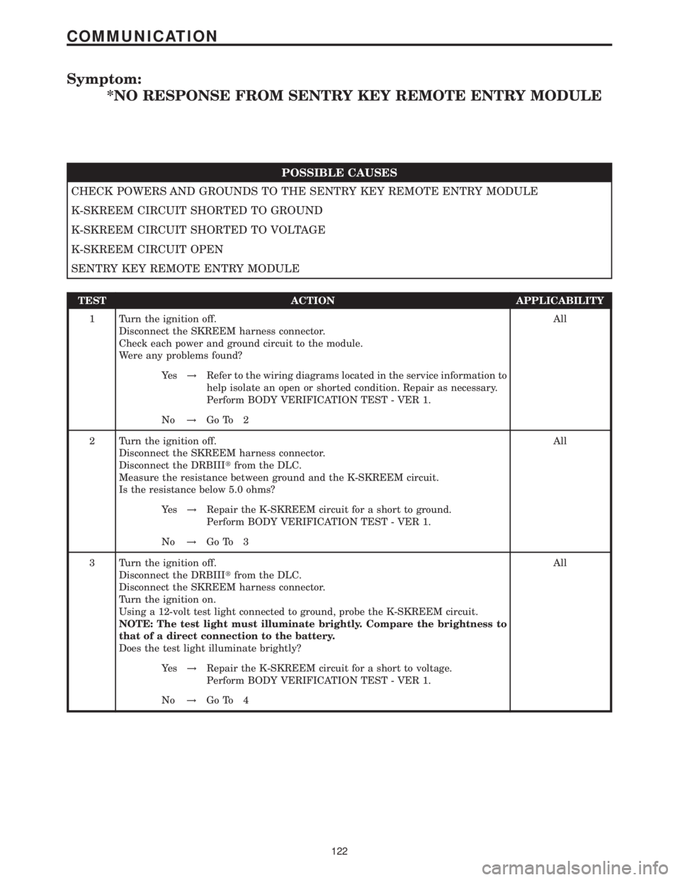
*NO RESPONSE FROM SENTRY KEY REMOTE ENTRY MODULE
POSSIBLE CAUSES
CHECK POWERS AND GROUNDS TO THE SENTRY KEY REMOTE ENTRY MODULE
K-SKREEM CIRCUIT SHORTED TO GROUND
K-SKREEM CIRCUIT SHORTED TO VOLTAGE
K-SKREEM CIRCUIT OPEN
SENTRY KEY REMOTE ENTRY MODULE
TEST ACTION APPLICABILITY
1 Turn the ignition off.
Disconnect the SKREEM harness connector.
Check each power and ground circuit to the module.
Were any problems found?All
Ye s!Refer to the wiring diagrams located in the service information to
help isolate an open or shorted condition. Repair as necessary.
Perform BODY VERIFICATION TEST - VER 1.
No!Go To 2
2 Turn the ignition off.
Disconnect the SKREEM harness connector.
Disconnect the DRBIIItfrom the DLC.
Measure the resistance between ground and the K-SKREEM circuit.
Is the resistance below 5.0 ohms?All
Ye s!Repair the K-SKREEM circuit for a short to ground.
Perform BODY VERIFICATION TEST - VER 1.
No!Go To 3
3 Turn the ignition off.
Disconnect the DRBIIItfrom the DLC.
Disconnect the SKREEM harness connector.
Turn the ignition on.
Using a 12-volt test light connected to ground, probe the K-SKREEM circuit.
NOTE: The test light must illuminate brightly. Compare the brightness to
that of a direct connection to the battery.
Does the test light illuminate brightly?All
Ye s!Repair the K-SKREEM circuit for a short to voltage.
Perform BODY VERIFICATION TEST - VER 1.
No!Go To 4
122
COMMUNICATION
Page 175 of 2305
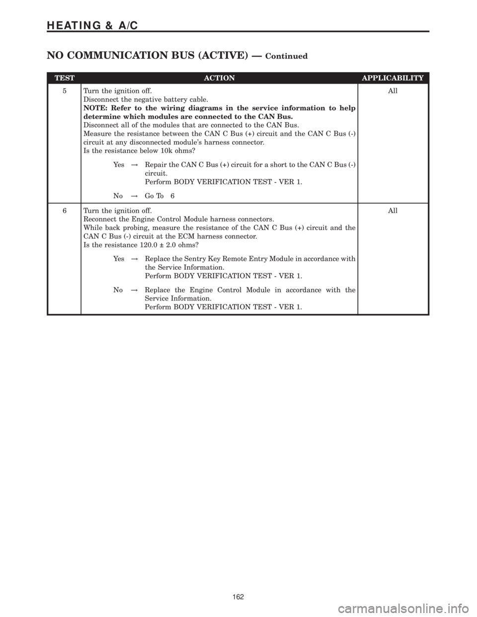
TEST ACTION APPLICABILITY
5 Turn the ignition off.
Disconnect the negative battery cable.
NOTE: Refer to the wiring diagrams in the service information to help
determine which modules are connected to the CAN Bus.
Disconnect all of the modules that are connected to the CAN Bus.
Measure the resistance between the CAN C Bus (+) circuit and the CAN C Bus (-)
circuit at any disconnected module's harness connector.
Is the resistance below 10k ohms?All
Ye s!Repair the CAN C Bus (+) circuit for a short to the CAN C Bus (-)
circuit.
Perform BODY VERIFICATION TEST - VER 1.
No!Go To 6
6 Turn the ignition off.
Reconnect the Engine Control Module harness connectors.
While back probing, measure the resistance of the CAN C Bus (+) circuit and the
CAN C Bus (-) circuit at the ECM harness connector.
Is the resistance 120.0 2.0 ohms?All
Ye s!Replace the Sentry Key Remote Entry Module in accordance with
the Service Information.
Perform BODY VERIFICATION TEST - VER 1.
No!Replace the Engine Control Module in accordance with the
Service Information.
Perform BODY VERIFICATION TEST - VER 1.
162
HEATING & A/C
NO COMMUNICATION BUS (ACTIVE) ÐContinued
Page 213 of 2305
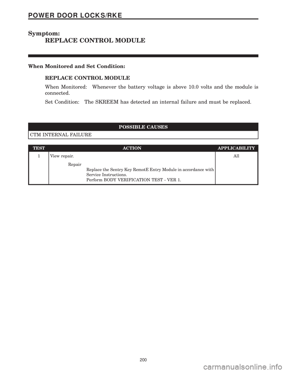
Symptom:
REPLACE CONTROL MODULE
When Monitored and Set Condition:
REPLACE CONTROL MODULE
When Monitored: Whenever the battery voltage is above 10.0 volts and the module is
connected.
Set Condition: The SKREEM has detected an internal failure and must be replaced.
POSSIBLE CAUSES
CTM INTERNAL FAILURE
TEST ACTION APPLICABILITY
1 View repair.All
Repair
Replace the Sentry Key RemotE Entry Module in accordance with
Service Instructions.
Perform BODY VERIFICATION TEST - VER 1.
200
POWER DOOR LOCKS/RKE
Page 216 of 2305
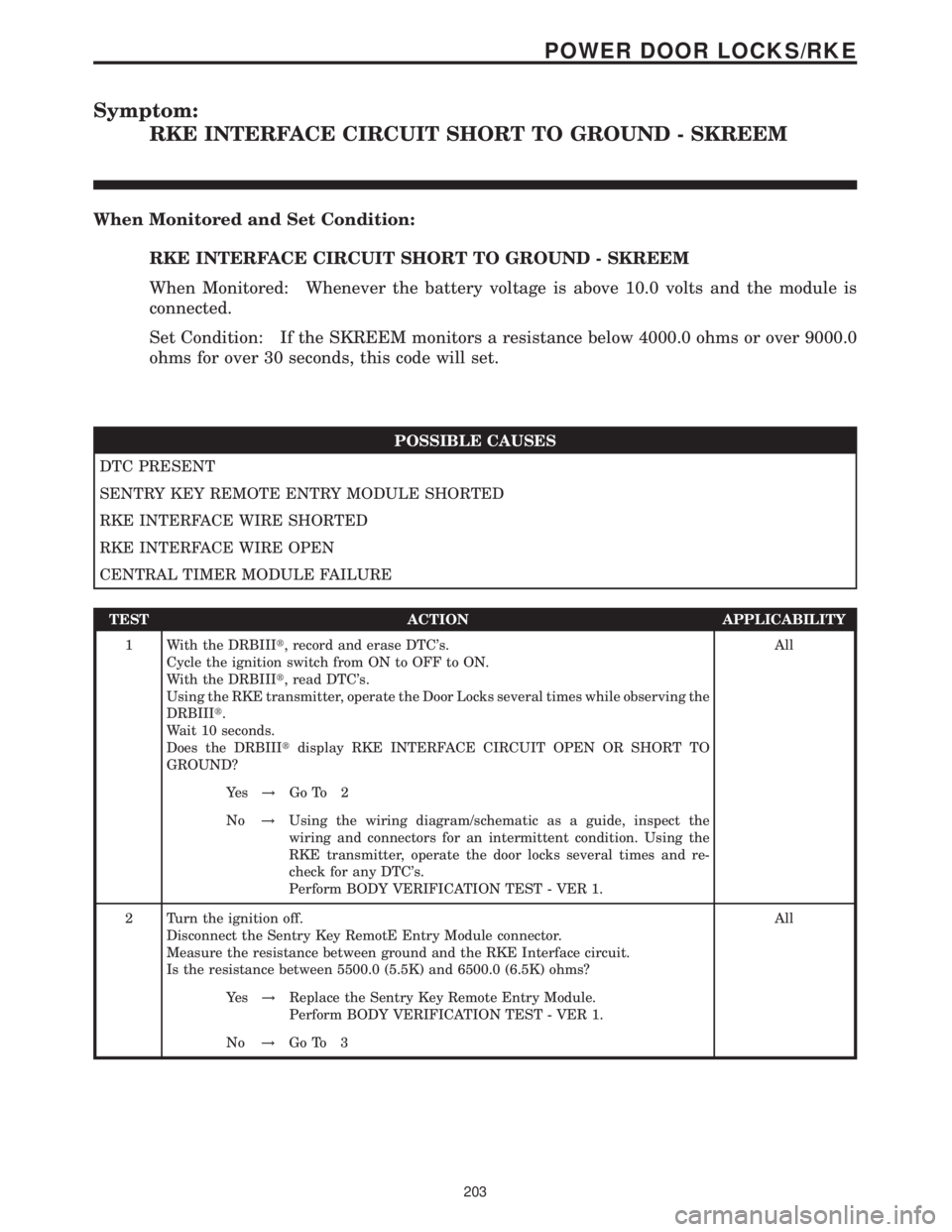
Symptom:
RKE INTERFACE CIRCUIT SHORT TO GROUND - SKREEM
When Monitored and Set Condition:
RKE INTERFACE CIRCUIT SHORT TO GROUND - SKREEM
When Monitored: Whenever the battery voltage is above 10.0 volts and the module is
connected.
Set Condition: If the SKREEM monitors a resistance below 4000.0 ohms or over 9000.0
ohms for over 30 seconds, this code will set.
POSSIBLE CAUSES
DTC PRESENT
SENTRY KEY REMOTE ENTRY MODULE SHORTED
RKE INTERFACE WIRE SHORTED
RKE INTERFACE WIRE OPEN
CENTRAL TIMER MODULE FAILURE
TEST ACTION APPLICABILITY
1 With the DRBIIIt, record and erase DTC's.
Cycle the ignition switch from ON to OFF to ON.
With the DRBIIIt, read DTC's.
Using the RKE transmitter, operate the Door Locks several times while observing the
DRBIIIt.
Wait 10 seconds.
Does the DRBIIItdisplay RKE INTERFACE CIRCUIT OPEN OR SHORT TO
GROUND?All
Ye s!Go To 2
No!Using the wiring diagram/schematic as a guide, inspect the
wiring and connectors for an intermittent condition. Using the
RKE transmitter, operate the door locks several times and re-
check for any DTC's.
Perform BODY VERIFICATION TEST - VER 1.
2 Turn the ignition off.
Disconnect the Sentry Key RemotE Entry Module connector.
Measure the resistance between ground and the RKE Interface circuit.
Is the resistance between 5500.0 (5.5K) and 6500.0 (6.5K) ohms?All
Ye s!Replace the Sentry Key Remote Entry Module.
Perform BODY VERIFICATION TEST - VER 1.
No!Go To 3
203
POWER DOOR LOCKS/RKE
Page 218 of 2305
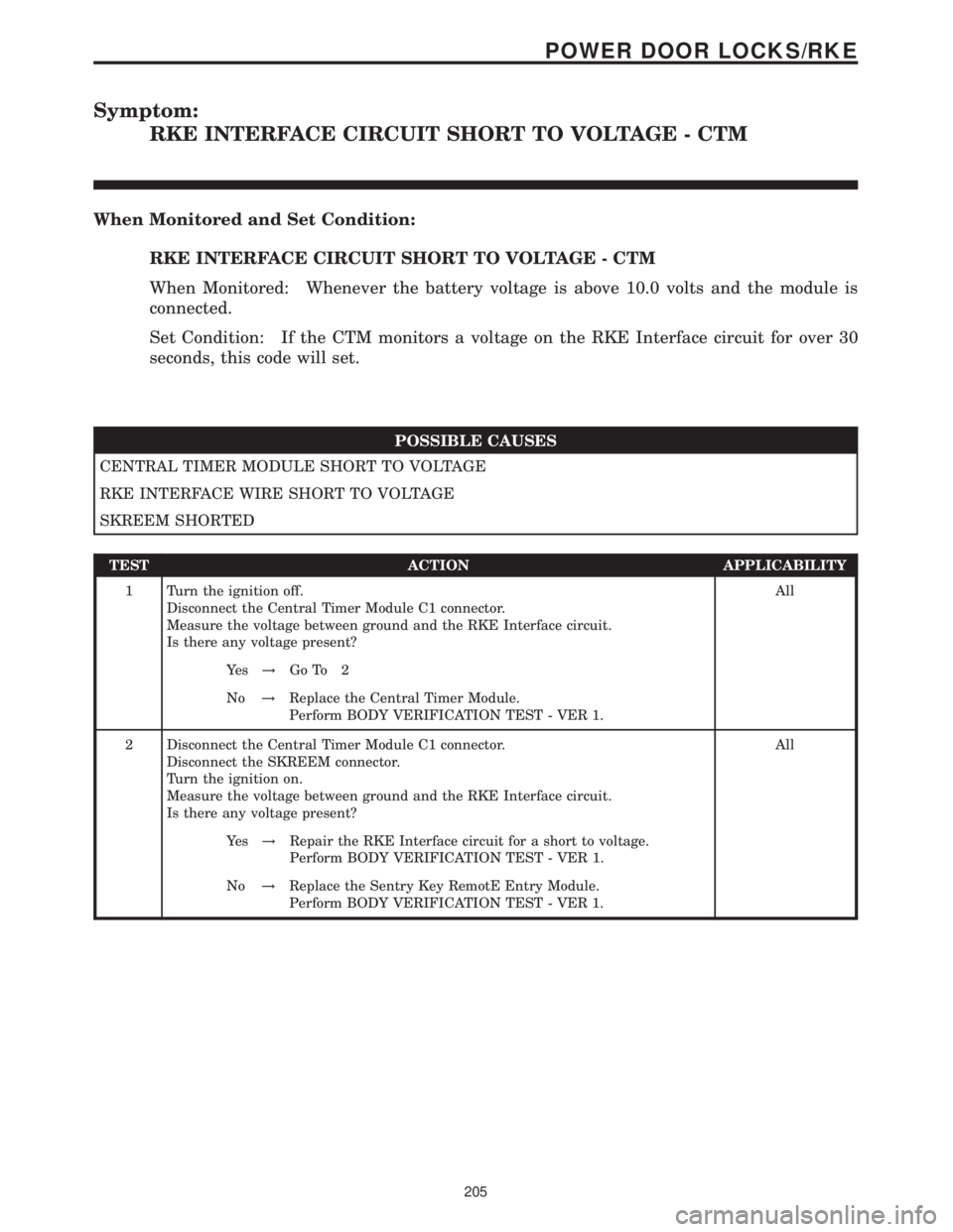
Symptom:
RKE INTERFACE CIRCUIT SHORT TO VOLTAGE - CTM
When Monitored and Set Condition:
RKE INTERFACE CIRCUIT SHORT TO VOLTAGE - CTM
When Monitored: Whenever the battery voltage is above 10.0 volts and the module is
connected.
Set Condition: If the CTM monitors a voltage on the RKE Interface circuit for over 30
seconds, this code will set.
POSSIBLE CAUSES
CENTRAL TIMER MODULE SHORT TO VOLTAGE
RKE INTERFACE WIRE SHORT TO VOLTAGE
SKREEM SHORTED
TEST ACTION APPLICABILITY
1 Turn the ignition off.
Disconnect the Central Timer Module C1 connector.
Measure the voltage between ground and the RKE Interface circuit.
Is there any voltage present?All
Ye s!Go To 2
No!Replace the Central Timer Module.
Perform BODY VERIFICATION TEST - VER 1.
2 Disconnect the Central Timer Module C1 connector.
Disconnect the SKREEM connector.
Turn the ignition on.
Measure the voltage between ground and the RKE Interface circuit.
Is there any voltage present?All
Ye s!Repair the RKE Interface circuit for a short to voltage.
Perform BODY VERIFICATION TEST - VER 1.
No!Replace the Sentry Key RemotE Entry Module.
Perform BODY VERIFICATION TEST - VER 1.
205
POWER DOOR LOCKS/RKE