2006 MERCEDES-BENZ SPRINTER service schedule
[x] Cancel search: service schedulePage 716 of 2305
LUBRICATION & MAINTENANCE
TABLE OF CONTENTS
page page
FLUID TYPES
DESCRIPTION
PARTS AND LUBRICANT
RECOMMENDATIONS...................1
AUTOMATIC TRANSMISSION FLUID - NAG1 . 1
AXLE FLUID..........................2
BRAKE FLUID.........................2
HOAT COOLANT.......................2
ENGINE OIL - DIESEL ENGINES...........3
FUEL REQUIREMENTS - DIESEL ENGINE . . . 4
POWER STEERING FLUID...............5
OPERATION - AUTOMATIC TRANSMISSION
FLUID...............................5
FLUID CAPACITIES
SPECIFICATIONS - FLUID CAPACITIES.......5FLUID FILL/CHECK LOCATIONS
INSPECTION - FLUID FILL/CHECK
LOCATIONS..........................5
HOISTING
STANDARD PROCEDURE - HOISTING........5
JUMP STARTING
STANDARD PROCEDURE - JUMP STARTING . . 6
TOWING
STANDARD PROCEDURE - TOWING.........7
MAINTENANCE SCHEDULES
DESCRIPTION..........................8
INTERNATIONAL SYMBOLS
DESCRIPTION..........................9
FLUID TYPES
DESCRIPTION
PARTS AND LUBRICANT RECOMMENDATIONS
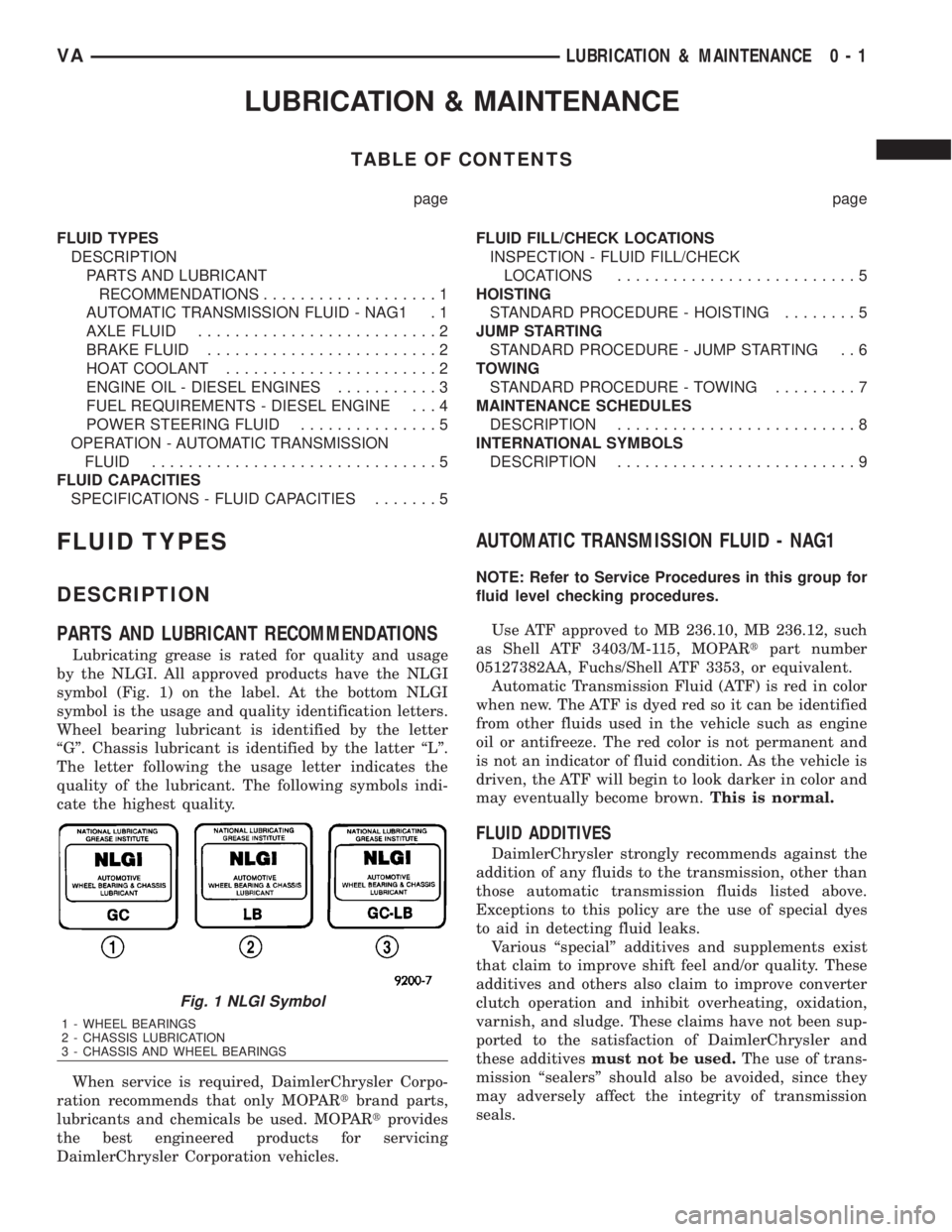
Lubricating grease is rated for quality and usage
by the NLGI. All approved products have the NLGI
symbol (Fig. 1) on the label. At the bottom NLGI
symbol is the usage and quality identification letters.
Wheel bearing lubricant is identified by the letter
ªGº. Chassis lubricant is identified by the latter ªLº.
The letter following the usage letter indicates the
quality of the lubricant. The following symbols indi-
cate the highest quality.
When service is required, DaimlerChrysler Corpo-
ration recommends that only MOPARtbrand parts,
lubricants and chemicals be used. MOPARtprovides
the best engineered products for servicing
DaimlerChrysler Corporation vehicles.
AUTOMATIC TRANSMISSION FLUID - NAG1
NOTE: Refer to Service Procedures in this group for
fluid level checking procedures.
Use ATF approved to MB 236.10, MB 236.12, such
as Shell ATF 3403/M-115, MOPARtpart number
05127382AA, Fuchs/Shell ATF 3353, or equivalent.
Automatic Transmission Fluid (ATF) is red in color
when new. The ATF is dyed red so it can be identified
from other fluids used in the vehicle such as engine
oil or antifreeze. The red color is not permanent and
is not an indicator of fluid condition. As the vehicle is
driven, the ATF will begin to look darker in color and
may eventually become brown.This is normal.
FLUID ADDITIVES
DaimlerChrysler strongly recommends against the
addition of any fluids to the transmission, other than
those automatic transmission fluids listed above.
Exceptions to this policy are the use of special dyes
to aid in detecting fluid leaks.
Various ªspecialº additives and supplements exist
that claim to improve shift feel and/or quality. These
additives and others also claim to improve converter
clutch operation and inhibit overheating, oxidation,
varnish, and sludge. These claims have not been sup-
ported to the satisfaction of DaimlerChrysler and
these additivesmust not be used.The use of trans-
mission ªsealersº should also be avoided, since they
may adversely affect the integrity of transmission
seals.
Fig. 1 NLGI Symbol
1 - WHEEL BEARINGS
2 - CHASSIS LUBRICATION
3 - CHASSIS AND WHEEL BEARINGS
VALUBRICATION & MAINTENANCE 0 - 1
Page 719 of 2305
DaimlerChrysler
Approved En-
gine OilSAE Rating MB Sheet
Number
Mobil Delvac 1 5W-40 228.5
Mobil Delvac
1300 Super (1)15W-40 228.3
Mobil SHC For-
mula MB5W-30 229.5
MOPARTPart
No.
04798231AD15W-40 228.3
Motul 8100 E-
Tech 0W-400W-40 229.3
Motul 8100 X-
cess 5W-405W-40 229.3
Panolin Indy SV 5W-40 229.3
Pennzoil Euro-
pean Formula
Ultra5W-30 229.5
Pennzoil Syn-
thetic European
Formula5W-40 229.3
Premium Syn-
thetik Motorenæl5W-30 229.5
QS Superfleet 15W-40 228.3
Quaker State
European For-
mula Ultra5W-30 229.5
Quaker State
Full Synthetic
European For-
mula5W-40 229.3
Quaker State
Super Series III
(1)15W-40 228.3
Raloy Diesel
Turbo MX15W-40 228.3
Raloy Motor
Diesel15W-40 228.3
Repsol Turbo
UHPD10W-40 228.5
Roshfrans Vol-
tro Diesel (1)15W-40 228.3
Shell Helix Ultra 5W-30 229.3
Shell Helix Ultra 5W-40 229.3
Shell Rimula X
CH-415W-40 228.3
Shell Rimula X
CH-420W-50 228.3DaimlerChrysler
Approved En-
gine OilSAE Rating MB Sheet
Number
Shell Rotella T
Multigrade (1)15W-40 228.3
Super Diesel
Oil MB-315W-40 228.3
Supreme Duty
Diesel Engine
Oil Multi- grade15W-40 228.3
Unoil GX-7 5W-40 229.3
Ursa Premium
TDX10W-30 228.3
Ursa Premium
TDX15W-40 228.3
Valvoline Syn-
Power MXL0W-30 229.3
(1) Engine oil also meets API classification CI-4.
Other oils may meet requirements - see oil label to
determine
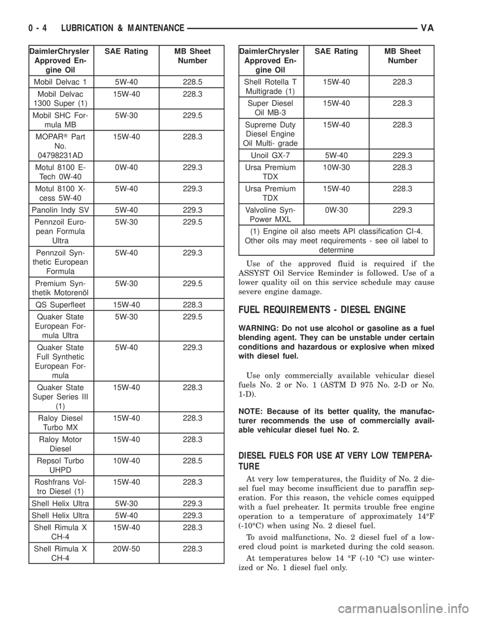
Use of the approved fluid is required if the
ASSYST Oil Service Reminder is followed. Use of a
lower quality oil on this service schedule may cause
severe engine damage.
FUEL REQUIREMENTS - DIESEL ENGINE
WARNING: Do not use alcohol or gasoline as a fuel
blending agent. They can be unstable under certain
conditions and hazardous or explosive when mixed
with diesel fuel.
Use only commercially available vehicular diesel
fuels No. 2 or No. 1 (ASTM D 975 No. 2-D or No.
1-D).
NOTE: Because of its better quality, the manufac-
turer recommends the use of commercially avail-
able vehicular diesel fuel No. 2.
DIESEL FUELS FOR USE AT VERY LOW TEMPERA-
TURE
At very low temperatures, the fluidity of No. 2 die-
sel fuel may become insufficient due to paraffin sep-
eration. For this reason, the vehicle comes equipped
with a fuel preheater. It permits trouble free engine
operation to a temperature of approximately 14ÉF
(-10ÉC) when using No. 2 diesel fuel.
To avoid malfunctions, No. 2 diesel fuel of a low-
ered cloud point is marketed during the cold season.
At temperatures below 14 ÉF (-10 ÉC) use winter-
ized or No. 1 diesel fuel only.
0 - 4 LUBRICATION & MAINTENANCEVA
Page 723 of 2305
effect panels. If necessary, remove the wheels from
the lifted end of the vehicle and lower the vehicle
closer to the ground, to increase the ground clearance
at the opposite end of the vehicle. Install lug nuts on
wheel attaching studs to retain brake drums.
RAMP ANGLE
If a vehicle with flat-bed towing equipment is used,
the approach ramp angle should not exceed 15
degrees.
TOWING WHEN KEYS ARE NOT AVAILABLE
When the vehicle is locked and keys are not avail-
able, use a flat bed hauler. A Wheel-lift or Sling-type
device can be used provided all the wheels are lifted
off the ground using tow dollies.
MAINTENANCE SCHEDULES
DESCRIPTION
The use of special lubricant additives is not recom-
mended. The use of such additives may affect the
warranty rights. With regard to legal stipulations
concerning emissions control, please note that
engines have to be serviced and adjusted in accor-
dance with special instructions and using special
measuring equipment. Modifications to or interfer-
ence with the emissions control systems are not per-
missible.
MAINTENANCE - WITHOUT ASSYST MAINTE-
NANCE COMPUTER
Maintenance Intervals
²Oil service ±Normal Operationevery 10,000
miles or 16,000 km or 12 months.
²Maintenance service every 30,000 miles or
48,000 km.
Additional work must be carried out at yearly
intervals.
MAINTENANCE - WITH ASSYST MAINTENANCE
COMPUTER
ASSYST provides information on the best possible
timing for maintenance work.
When the next maintenance service is due, this
will be indicated in the multi-function display with
the wrench icon symbol displayed in km/miles or
days.
²One wrench icon showing indicates Oil Service
is necessary.
²Two wrench icons showing indicates Mainte-
nance Service is necessary ± displayed in km/miles or
days.
If the display shows the number of days, a clock
symbol will also appear in the multi-function display.You should have the maintenance performed
within the stated period/distance.
The service indicator will be reset after an oil ser-
vice and/or maintenance service has been performed.
REGULAR CHECK - UPS
To maintain the safe operation of the vehicle, it is
recommended that the following tasks be performed
on a regular basis (i.e. weekly or whenever the vehi-
cle is refueled). Check:
²Engine oil level
²Brake system - fluid level
²Battery - acid level
²Windshield washer system and headlamp clean-
ing system - fluid level
²Mechanical assemblies (e.g. engine, transmis-
sion, etc.) - check for leaks
²Condition of tires and tires pressures
²All exterior lights
SPECIAL MAINTENANCE REQUIREMENTS
If bodies built by manufacturers other than
DaimlerChrysler Corporation are fitted to the vehi-
cle, the maintenance requirements and lubrication
intervals specified by the body manufacturer must be
adhered to, in addition to all standard maintenance
requirements.
Coolant
Corrosion inhibitor/antifreeze concentration in the
coolant should be checked before the onset of winter
(once year in countries with high prevailing temper-
atures).
Replace the coolant every five years or 100,000
miles.
Dust Filter for Heating / Ventilation Replacement
The dust filter and the tailgate interior filter are to
be renewed during routine maintenance service. If
operating conditions are dusty, these filters should be
renewed more frequently.
ENGINE OIL CHANGE AND FILTER REPLACEMENT
At a minimum, change the engine oil and oil filter
once a year ± even if the vehicle mileage per year is
extremely low. For standard oil service schedules
refer to the chapter oil service and maintenance ser-
vice.
Once a Year
Select the viscosity of the engine oil (SAE classes)
according to the outside air temperature.
Only use engine oil approved by DaimlerChrysler
Corporation if following the ASSYST system guide-
lines.
0 - 8 LUBRICATION & MAINTENANCEVA
Page 867 of 2305

For battery system maintenance schedules and
jump starting procedures, see the owner's manual in
the vehicle glove box. Optionally, refer to the Lubri-
cation and Maintenance section of this manual for
the recommended battery maintenance schedules and
for the proper battery jump starting procedure. While
battery charging can be considered a maintenance
procedure, the battery charging procedure and
related information are located later in this section of
this service manual. This was done because the bat-
tery must be fully-charged before any battery system
diagnosis or testing procedures can be performed.
OPERATION
The battery system is designed to provide a safe,
efficient, reliable and mobile means of delivering and
storing electrical energy. This electrical energy is
required to operate the engine starting system, as
well as to operate many of the other vehicle acces-
sory systems for limited durations while the engine
and/or the charging system are not operating. The
battery system is also designed to provide a reserve
of electrical energy to supplement the charging sys-
tem for short durations while the engine is running
and the electrical current demands of the vehicle
exceed the output of the charging system. In addition
to delivering, and storing electrical energy for the
vehicle, the battery system serves as a capacitor and
voltage stabilizer for the vehicle electrical system. It
absorbs most abnormal or transient voltages caused
by the switching of any of the electrical components
or circuits in the vehicle.
DIAGNOSIS AND TESTING - BATTERY SYSTEM
The battery, starting, and charging systems in the
vehicle operate with one another and must be tested
as a complete system. In order for the engine to start
and the battery to maintain its charge properly, all ofthe components that are used in these systems must
perform within specifications. It is important that
the battery, starting, and charging systems be thor-
oughly tested and inspected any time a battery needs
to be charged or replaced. The cause of abnormal bat-
tery discharge, overcharging or early battery failure
must be diagnosed and corrected before a battery is
replaced and before a vehicle is returned to service.
The service information for these systems has been
separated within this service manual to make it eas-
ier to locate the specific information you are seeking.
However, when attempting to diagnose any of these
systems, it is important that you keep their interde-
pendency in mind.
The diagnostic procedures used for the battery,
starting, and charging systems include the most
basic conventional diagnostic methods, to the more
sophisticated On-Board Diagnostics (OBD) built into
the Powertrain Control Module (PCM). Use of an
induction-type milliampere ammeter, a volt/ohmme-
ter, a battery charger, a carbon pile rheostat (load
tester) and a 12-volt test lamp may be required. All
OBD-sensed systems are monitored by the PCM.
Each monitored circuit is assigned a Diagnostic Trou-
ble Code (DTC). The PCM will store a DTC in elec-
tronic memory for any failure it detects. Refer to
Charging System for the proper charging system on-
board diagnostic test procedures.
MICRO 420 BATTERY TESTER
The Micro 420 automotive battery tester is
designed to help the dealership technicians diagnose
the cause of a defective battery. Follow the instruc-
tion manual supplied with the tester to properly
diagnose a vehicle. If the instruction manual is not
available refer to the standard procedure in this sec-
tion, which includes the directions for using the
Micro 420 battery tester.
8F - 2 BATTERY SYSTEMVA
Page 870 of 2305
CLEANING
The following information details the recommended
cleaning procedures for the battery and related com-
ponents. In addition to the maintenance schedules
found in this service manual and the owner's man-
ual, it is recommended that these procedures be per-
formed any time the battery or related components
must be removed for vehicle service.
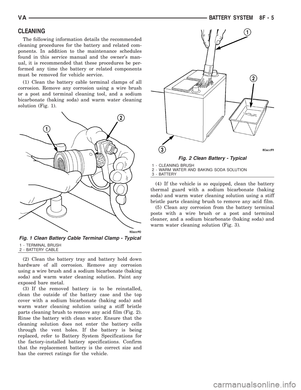
(1) Clean the battery cable terminal clamps of all
corrosion. Remove any corrosion using a wire brush
or a post and terminal cleaning tool, and a sodium
bicarbonate (baking soda) and warm water cleaning
solution (Fig. 1).
(2) Clean the battery tray and battery hold down
hardware of all corrosion. Remove any corrosion
using a wire brush and a sodium bicarbonate (baking
soda) and warm water cleaning solution. Paint any
exposed bare metal.
(3) If the removed battery is to be reinstalled,
clean the outside of the battery case and the top
cover with a sodium bicarbonate (baking soda) and
warm water cleaning solution using a stiff bristle
parts cleaning brush to remove any acid film (Fig. 2).
Rinse the battery with clean water. Ensure that the
cleaning solution does not enter the battery cells
through the vent holes. If the battery is being
replaced, refer to Battery System Specifications for
the factory-installed battery specifications. Confirm
that the replacement battery is the correct size and
has the correct ratings for the vehicle.(4) If the vehicle is so equipped, clean the battery
thermal guard with a sodium bicarbonate (baking
soda) and warm water cleaning solution using a stiff
bristle parts cleaning brush to remove any acid film.
(5) Clean any corrosion from the battery terminal
posts with a wire brush or a post and terminal
cleaner, and a sodium bicarbonate (baking soda) and
warm water cleaning solution (Fig. 3).
Fig. 1 Clean Battery Cable Terminal Clamp - Typical
1 - TERMINAL BRUSH
2 - BATTERY CABLE
Fig. 2 Clean Battery - Typical
1 - CLEANING BRUSH
2 - WARM WATER AND BAKING SODA SOLUTION
3 - BATTERY
VABATTERY SYSTEM 8F - 5
Page 2246 of 2305
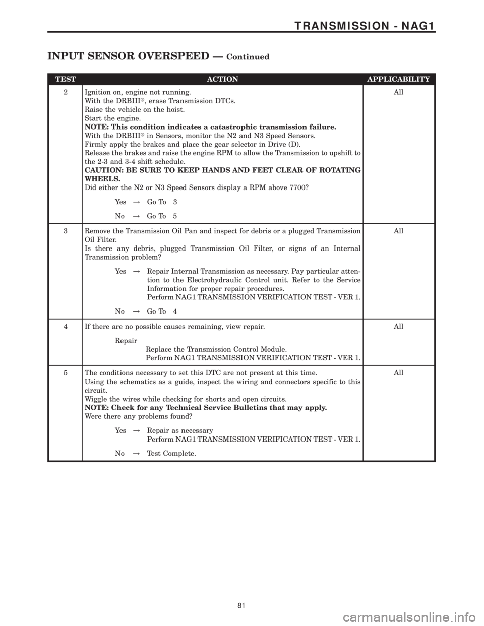
TEST ACTION APPLICABILITY
2 Ignition on, engine not running.
With the DRBIIIt, erase Transmission DTCs.
Raise the vehicle on the hoist.
Start the engine.
NOTE: This condition indicates a catastrophic transmission failure.
With the DRBIIItin Sensors, monitor the N2 and N3 Speed Sensors.
Firmly apply the brakes and place the gear selector in Drive (D).
Release the brakes and raise the engine RPM to allow the Transmission to upshift to
the 2-3 and 3-4 shift schedule.
CAUTION: BE SURE TO KEEP HANDS AND FEET CLEAR OF ROTATING
WHEELS.
Did either the N2 or N3 Speed Sensors display a RPM above 7700?All
Ye s!Go To 3
No!Go To 5
3 Remove the Transmission Oil Pan and inspect for debris or a plugged Transmission
Oil Filter.
Is there any debris, plugged Transmission Oil Filter, or signs of an Internal
Transmission problem?All
Ye s!Repair Internal Transmission as necessary. Pay particular atten-
tion to the Electrohydraulic Control unit. Refer to the Service
Information for proper repair procedures.
Perform NAG1 TRANSMISSION VERIFICATION TEST - VER 1.
No!Go To 4
4 If there are no possible causes remaining, view repair. All
Repair
Replace the Transmission Control Module.
Perform NAG1 TRANSMISSION VERIFICATION TEST - VER 1.
5 The conditions necessary to set this DTC are not present at this time.
Using the schematics as a guide, inspect the wiring and connectors specific to this
circuit.
Wiggle the wires while checking for shorts and open circuits.
NOTE: Check for any Technical Service Bulletins that may apply.
Were there any problems found?All
Ye s!Repair as necessary
Perform NAG1 TRANSMISSION VERIFICATION TEST - VER 1.
No!Test Complete.
81
TRANSMISSION - NAG1
INPUT SENSOR OVERSPEED ÐContinued