2006 MERCEDES-BENZ SPRINTER hood cable
[x] Cancel search: hood cablePage 721 of 2305
HOIST
A vehicle can be lifted with:
²A single-post, frame-contact hoist.
²A twin-post, chassis hoist.
²A ramp-type, drive-on hoist.
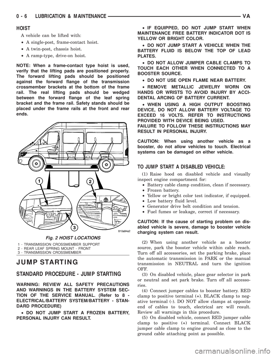
NOTE: When a frame-contact type hoist is used,
verify that the lifting pads are positioned properly.
The forward lifting pads should be positioned
against the forward flange of the transmission
crossmember brackets at the bottom of the frame
rail. The real lifting pads should be wedged
between the forward flange of the leaf spring
bracket and the frame rail. Safety stands should be
placed under the frame rails at the front and rear
ends.
JUMP STARTING
STANDARD PROCEDURE - JUMP STARTING
WARNING: REVIEW ALL SAFETY PRECAUTIONS
AND WARNINGS IN THE BATTERY SYSTEM SEC-
TION OF THE SERVICE MANUAL. (Refer to 8 -
ELECTRICAL/BATTERY SYSTEM/BATTERY - STAN-
DARD PROCEDURE)
²DO NOT JUMP START A FROZEN BATTERY,
PERSONAL INJURY CAN RESULT.²IF EQUIPPED, DO NOT JUMP START WHEN
MAINTENANCE FREE BATTERY INDICATOR DOT IS
YELLOW OR BRIGHT COLOR.
²DO NOT JUMP START A VEHICLE WHEN THE
BATTERY FLUID IS BELOW THE TOP OF LEAD
PLATES.
²DO NOT ALLOW JUMPER CABLE CLAMPS TO
TOUCH EACH OTHER WHEN CONNECTED TO A
BOOSTER SOURCE.
²DO NOT USE OPEN FLAME NEAR BATTERY.
²REMOVE METALLIC JEWELRY WORN ON
HANDS OR WRISTS TO AVOID INJURY BY ACCI-
DENTAL ARCING OF BATTERY CURRENT.
²WHEN USING A HIGH OUTPUT BOOSTING
DEVICE, DO NOT ALLOW BATTERY VOLTAGE TO
EXCEED 16 VOLTS. REFER TO INSTRUCTIONS
PROVIDED WITH DEVICE BEING USED.
FAILURE TO FOLLOW THESE INSTRUCTIONS MAY
RESULT IN PERSONAL INJURY.
CAUTION: When using another vehicle as a
booster, do not allow vehicles to touch. Electrical
systems can be damaged on either vehicle.
TO JUMP START A DISABLED VEHICLE:
(1) Raise hood on disabled vehicle and visually
inspect engine compartment for:
²Battery cable clamp condition, clean if necessary.
²Frozen battery.
²Yellow or bright color test indicator, if equipped.
²Low battery fluid level.
²Generator drive belt condition and tension.
²Fuel fumes or leakage, correct if necessary.
CAUTION: If the cause of starting problem on dis-
abled vehicle is severe, damage to booster vehicle
charging system can result.
(2) When using another vehicle as a booster
source, park the booster vehicle within cable reach.
Turn off all accessories, set the parking brake, place
the automatic transmission in PARK or the manual
transmission in NEUTRAL and turn the ignition
OFF.
(3) On disabled vehicle, place gear selector in park
or neutral and set park brake. Turn off all accesso-
ries.
(4) Connect jumper cables to booster battery. RED
clamp to positive terminal (+). BLACK clamp to neg-
ative terminal (-). DO NOT allow clamps at opposite
end of cables to touch, electrical arc will result.
Review all warnings in this procedure.
(5) On disabled vehicle, connect RED jumper cable
clamp to positive (+) terminal. Connect BLACK
jumper cable clamp to engine ground as close to the
ground cable attaching point as possible.
Fig. 2 HOIST LOCATIONS
1 - TRANSMISSION CROSSMEMBER SUPPORT
2 - REAR LEAF SPRING MOUNT - FRONT
3 - TRANSMISSION CROSSMEMBER
0 - 6 LUBRICATION & MAINTENANCEVA
Page 866 of 2305
ENGINE SYSTEMS
TABLE OF CONTENTS
page page
BATTERY SYSTEM......................... 1
CHARGING SYSTEM....................... 17STARTING SYSTEM....................... 28
BATTERY SYSTEM
TABLE OF CONTENTS
page page
BATTERY SYSTEM
DESCRIPTION..........................1
OPERATION............................2
DIAGNOSIS AND TESTING - BATTERY
SYSTEM.............................2
CLEANING.............................5
INSPECTION...........................6
SPECIAL TOOLS
BATTERY SYSTEM SPECIAL TOOLS.......6
BATTERY
DESCRIPTION..........................6
OPERATION............................7
DIAGNOSIS AND TESTING - BATTERY.......7
STANDARD PROCEDURE
STANDARD PROCEDURE - BATTERY
CHARGING...........................8
STANDARD PROCEDURE - OPEN-CIRCUIT
VOLTAGE TEST........................9
STANDARD PROCEDURE - IGNITION-OFF
DRAW TEST.........................10
STANDARD PROCEDURE - USING MICRO
420 BATTERY TESTER.................11
STANDARD PROCEDURE - CHECKING
BATTERY ELECTROLYTE LEVEL.........12REMOVAL
UNDER HOOD BATTERY REMOVAL.......12
AUXILIARY BATTERY REMOVAL..........13
INSTALLATION
UNDER HOOD BATTERY INSTALLATION . . . 13
AUXILIARY BATTERY INSTALLATION......13
BATTERY HOLDDOWN
DESCRIPTION.........................13
REMOVAL.............................13
INSTALLATION.........................14
BATTERY CABLES
DESCRIPTION.........................14
OPERATION...........................14
DIAGNOSIS AND TESTING - BATTERY
CABLES............................14
REMOVAL.............................16
INSTALLATION.........................16
BATTERY TRAY
DESCRIPTION.........................16
OPERATION...........................16
REMOVAL.............................16
INSTALLATION.........................16
BATTERY SYSTEM
DESCRIPTION
A single 12-volt battery is standard factory-in-
stalled equipment on this model. Some vehicles are
equipped with a second auxiliary battery for running
additional electrical equipment. The standard battery
is located in the engine compartment, while the aux-
iliary battery (if equipped) is located under the pas-
sengers front seat. The battery system for this
vehicle covers the following related components,
which are covered in further detail later in this sec-
tion of the service manual:²Battery- The 12v storage battery(s) provides a
reliable means of storing a renewable source of elec-
trical energy within the vehicle.
²Battery Cables- The battery cables connect
the battery terminal posts to the vehicle electrical
system.
²Battery Holddown- The battery holddown
hardware secures the battery in the battery tray in
the engine compartment.
²Battery Tray- The battery tray provides a
secure mounting location in the vehicle for the bat-
tery and an anchor point for the battery holddown
hardware.
VAENGINE SYSTEMS 8F - 1
Page 875 of 2305
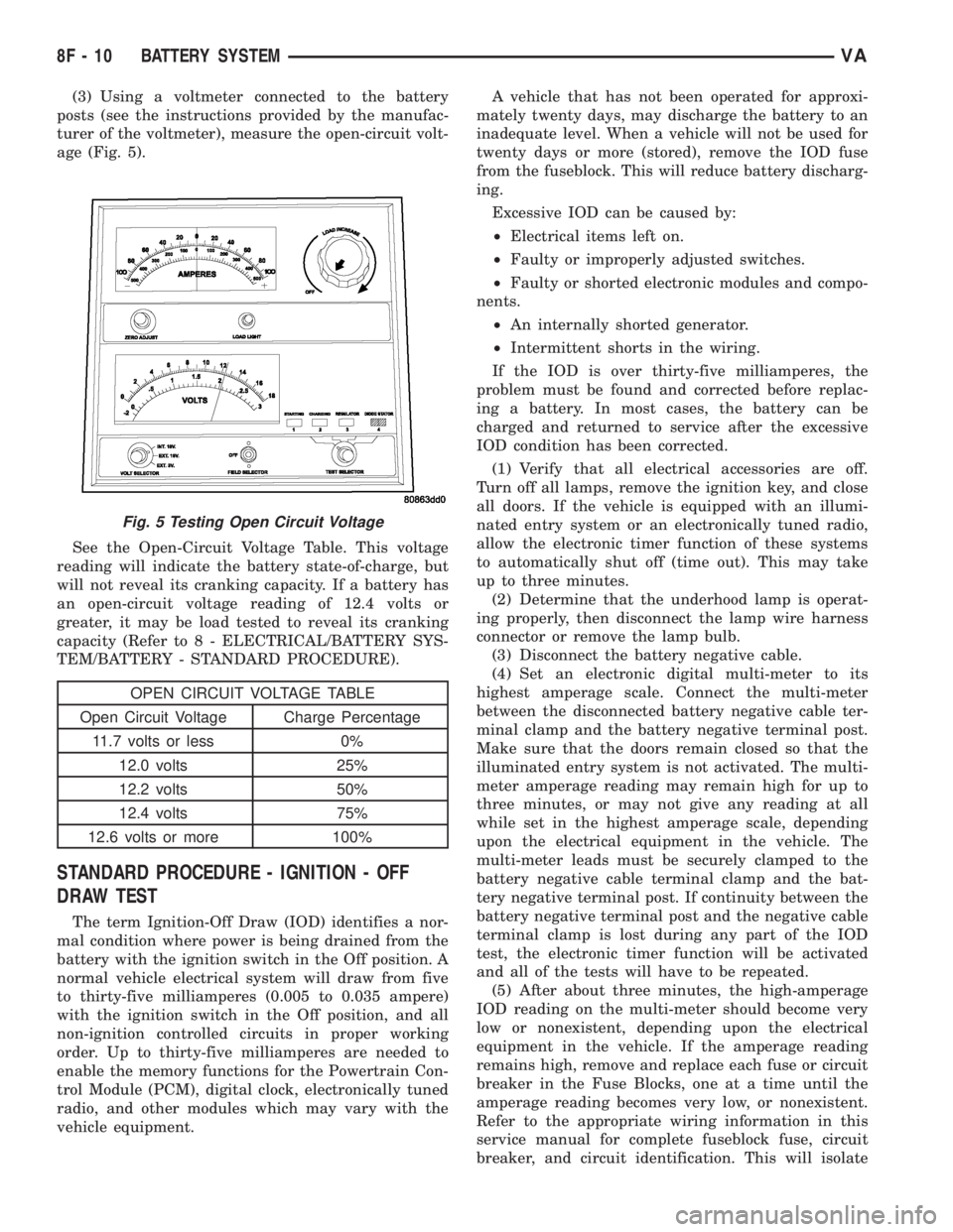
(3) Using a voltmeter connected to the battery
posts (see the instructions provided by the manufac-
turer of the voltmeter), measure the open-circuit volt-
age (Fig. 5).
See the Open-Circuit Voltage Table. This voltage
reading will indicate the battery state-of-charge, but
will not reveal its cranking capacity. If a battery has
an open-circuit voltage reading of 12.4 volts or
greater, it may be load tested to reveal its cranking
capacity (Refer to 8 - ELECTRICAL/BATTERY SYS-
TEM/BATTERY - STANDARD PROCEDURE).
OPEN CIRCUIT VOLTAGE TABLE
Open Circuit Voltage Charge Percentage
11.7 volts or less 0%
12.0 volts 25%
12.2 volts 50%
12.4 volts 75%
12.6 volts or more 100%
STANDARD PROCEDURE - IGNITION - OFF
DRAW TEST
The term Ignition-Off Draw (IOD) identifies a nor-
mal condition where power is being drained from the
battery with the ignition switch in the Off position. A
normal vehicle electrical system will draw from five
to thirty-five milliamperes (0.005 to 0.035 ampere)
with the ignition switch in the Off position, and all
non-ignition controlled circuits in proper working
order. Up to thirty-five milliamperes are needed to
enable the memory functions for the Powertrain Con-
trol Module (PCM), digital clock, electronically tuned
radio, and other modules which may vary with the
vehicle equipment.A vehicle that has not been operated for approxi-
mately twenty days, may discharge the battery to an
inadequate level. When a vehicle will not be used for
twenty days or more (stored), remove the IOD fuse
from the fuseblock. This will reduce battery discharg-
ing.
Excessive IOD can be caused by:
²Electrical items left on.
²Faulty or improperly adjusted switches.
²Faulty or shorted electronic modules and compo-
nents.
²An internally shorted generator.
²Intermittent shorts in the wiring.
If the IOD is over thirty-five milliamperes, the
problem must be found and corrected before replac-
ing a battery. In most cases, the battery can be
charged and returned to service after the excessive
IOD condition has been corrected.
(1) Verify that all electrical accessories are off.
Turn off all lamps, remove the ignition key, and close
all doors. If the vehicle is equipped with an illumi-
nated entry system or an electronically tuned radio,
allow the electronic timer function of these systems
to automatically shut off (time out). This may take
up to three minutes.
(2) Determine that the underhood lamp is operat-
ing properly, then disconnect the lamp wire harness
connector or remove the lamp bulb.
(3) Disconnect the battery negative cable.
(4) Set an electronic digital multi-meter to its
highest amperage scale. Connect the multi-meter
between the disconnected battery negative cable ter-
minal clamp and the battery negative terminal post.
Make sure that the doors remain closed so that the
illuminated entry system is not activated. The multi-
meter amperage reading may remain high for up to
three minutes, or may not give any reading at all
while set in the highest amperage scale, depending
upon the electrical equipment in the vehicle. The
multi-meter leads must be securely clamped to the
battery negative cable terminal clamp and the bat-
tery negative terminal post. If continuity between the
battery negative terminal post and the negative cable
terminal clamp is lost during any part of the IOD
test, the electronic timer function will be activated
and all of the tests will have to be repeated.
(5) After about three minutes, the high-amperage
IOD reading on the multi-meter should become very
low or nonexistent, depending upon the electrical
equipment in the vehicle. If the amperage reading
remains high, remove and replace each fuse or circuit
breaker in the Fuse Blocks, one at a time until the
amperage reading becomes very low, or nonexistent.
Refer to the appropriate wiring information in this
service manual for complete fuseblock fuse, circuit
breaker, and circuit identification. This will isolate
Fig. 5 Testing Open Circuit Voltage
8F - 10 BATTERY SYSTEMVA
Page 877 of 2305
BATTERY TEST RESULTS
GOOD BATTERY Return to service
GOOD - RECHARGE Fully charge battery and
return to service
CHARGE & RETEST Fully charge battery and
retest battery
REPLACE BATTERY Replace the battery and
retest complete system
BAD-CELL REPLACE Replace the battery and
retest complete system
NOTE: The SERVICE CODE is required on every
warranty claim submitted for battery replacement.
STANDARD PROCEDURE - CHECKING BATTERY
ELECTROLYTE LEVEL
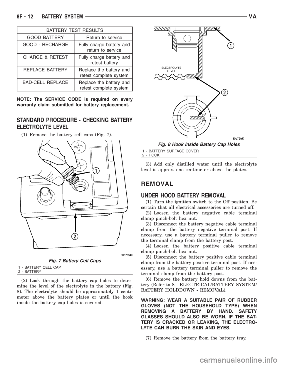
(1) Remove the battery cell caps (Fig. 7).
(2) Look through the battery cap holes to deter-
mine the level of the electrolyte in the battery (Fig.
8). The electrolyte should be approximately 1 centi-
meter above the battery plates or until the hook
inside the battery cap holes is covered.(3) Add only distilled water until the electrolyte
level is approx. one centimeter above the plates.
REMOVAL
UNDER HOOD BATTERY REMOVAL
(1) Turn the ignition switch to the Off position. Be
certain that all electrical accessories are turned off.
(2) Loosen the battery negative cable terminal
clamp pinch-bolt hex nut.
(3) Disconnect the battery negative cable terminal
clamp from the battery negative terminal post. If
necessary, use a battery terminal puller to remove
the terminal clamp from the battery post.
(4) Loosen the battery positive cable terminal
clamp pinch-bolt hex nut.
(5) Disconnect the battery positive cable terminal
clamp from the battery positive terminal post. If nec-
essary, use a battery terminal puller to remove the
terminal clamp from the battery post.
(6) Remove the battery hold downs from the bat-
tery (Refer to 8 - ELECTRICAL/BATTERY SYSTEM/
BATTERY HOLDDOWN - REMOVAL).
WARNING: WEAR A SUITABLE PAIR OF RUBBER
GLOVES (NOT THE HOUSEHOLD TYPE) WHEN
REMOVING A BATTERY BY HAND. SAFETY
GLASSES SHOULD ALSO BE WORN. IF THE BAT-
TERY IS CRACKED OR LEAKING, THE ELECTRO-
LYTE CAN BURN THE SKIN AND EYES.
(7) Remove the battery from the battery tray.
Fig. 7 Battery Cell Caps
1 - BATTERY CELL CAP
2 - BATTERY
Fig. 8 Hook Inside Battery Cap Holes
1 - BATTERY SURFACE COVER
2 - HOOK
8F - 12 BATTERY SYSTEMVA
Page 878 of 2305
AUXILIARY BATTERY REMOVAL
(1) Turn the ignition switch to the Off position. Be
certain that all electrical accessories are turned off.
(2) Remove the passenger front seat assembly.
Refer to the Body section for procedure.
(3) Remove the top cover from the seat base
assembly.
(4) Loosen the battery negative cable terminal
clamp pinch-bolt hex nut.
(5) Disconnect the battery negative cable terminal
clamp from the battery negative terminal post. If
necessary, use a battery terminal puller to remove
the terminal clamp from the battery post.
(6) Loosen the battery positive cable terminal
clamp pinch-bolt hex nut.
(7) Disconnect the battery positive cable terminal
clamp from the battery positive terminal post. If nec-
essary, use a battery terminal puller to remove the
terminal clamp from the battery post.
(8) Remove the battery hold downs from the bat-
tery (Refer to 8 - ELECTRICAL/BATTERY SYSTEM/
BATTERY HOLDDOWN - REMOVAL).
WARNING: WEAR A SUITABLE PAIR OF RUBBER
GLOVES (NOT THE HOUSEHOLD TYPE) WHEN
REMOVING A BATTERY BY HAND. SAFETY
GLASSES SHOULD ALSO BE WORN. IF THE BAT-
TERY IS CRACKED OR LEAKING, THE ELECTRO-
LYTE CAN BURN THE SKIN AND EYES.
(9) Remove the battery from the battery tray.
INSTALLATION
UNDER HOOD BATTERY INSTALLATION
(1) Position the battery onto the battery tray.
Ensure that the battery positive and negative termi-
nal posts are correctly positioned. The battery cable
terminal clamps must reach the correct battery ter-
minal post without stretching the cables.
(2) Reinstall the battery hold downs onto the bat-
tery (Refer to 8 - ELECTRICAL/BATTERY SYSTEM/
BATTERY HOLDDOWN - INSTALLATION).
CAUTION: Be certain that the battery cable terminal
clamps are connected to the correct battery termi-
nal posts. Reverse battery polarity may damage
electrical components of the vehicle.
(3) Reconnect the battery positive cable terminal
clamp to the battery positive terminal post. Tighten
the terminal clamp pinch-bolt hex nut to 11.8 N´m
(105 in. lbs.).
(4) Reconnect the battery negative cable terminal
clamp to the battery negative terminal post. Tighten
the terminal clamp pinch-bolt hex nut to 7.9 N´m (70
in. lbs.).(5) Apply a thin coating of petroleum jelly or chas-
sis grease to the exposed surfaces of the battery cable
terminal clamps and the battery terminal posts.
AUXILIARY BATTERY INSTALLATION
(1) Position the battery onto the battery tray.
Ensure that the battery positive and negative termi-
nal posts are correctly positioned. The battery cable
terminal clamps must reach the correct battery ter-
minal post without stretching the cables.
(2) Reinstall the battery hold downs onto the bat-
tery (Refer to 8 - ELECTRICAL/BATTERY SYSTEM/
BATTERY HOLDDOWN - INSTALLATION).
CAUTION: Be certain that the battery cable terminal
clamps are connected to the correct battery termi-
nal posts. Reverse battery polarity may damage
electrical components of the vehicle.
(3) Reconnect the battery positive cable terminal
clamp to the battery positive terminal post. Tighten
the terminal clamp pinch-bolt hex nut to 11.8 N´m
(105 in. lbs.).
(4) Reconnect the battery negative cable terminal
clamp to the battery negative terminal post. Tighten
the terminal clamp pinch-bolt hex nut to 7.9 N´m (70
in. lbs.).
(5) Apply a thin coating of petroleum jelly or chas-
sis grease to the exposed surfaces of the battery cable
terminal clamps and the battery terminal posts.
(6) Install the top cover on the seat base assembly.
(7) Install the passenger front seat assembly. Refer
to the Body section for procedure.
BATTERY HOLDDOWN
DESCRIPTION
The battery hold down hardware includes two hex
nuts with washers and two hold down brackets. The
battery hold down brackets are formed of stamped
steel. The hold down assembly is coated for corrosion
protection.
When installing a battery into the battery tray, be
certain that the hold down hardware is properly
installed and that the fasteners are tightened to the
proper specifications. Improper hold down fastener
tightness, whether too loose or too tight, can result in
damage to the battery, the vehicle or both.
REMOVAL
(1) Turn the ignition switch to the Off position. Be
certain that all electrical accessories are turned off.
(2) Remove the two nuts that secure the battery
hold down brackets to the battery tray.
(3) Remove the battery hold down brackets.
VABATTERY SYSTEM 8F - 13
Page 899 of 2305
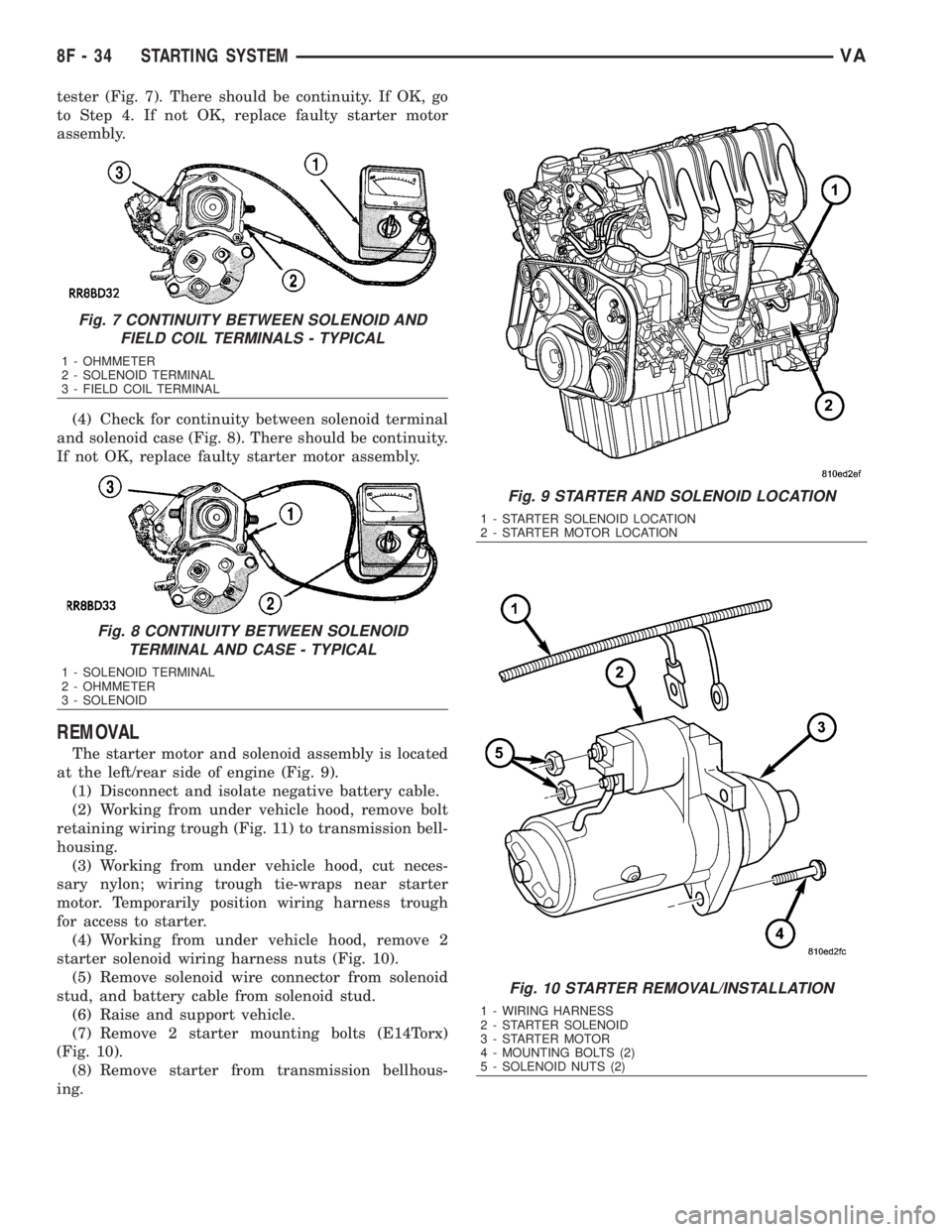
tester (Fig. 7). There should be continuity. If OK, go
to Step 4. If not OK, replace faulty starter motor
assembly.
(4) Check for continuity between solenoid terminal
and solenoid case (Fig. 8). There should be continuity.
If not OK, replace faulty starter motor assembly.
REMOVAL
The starter motor and solenoid assembly is located
at the left/rear side of engine (Fig. 9).
(1) Disconnect and isolate negative battery cable.
(2) Working from under vehicle hood, remove bolt
retaining wiring trough (Fig. 11) to transmission bell-
housing.
(3) Working from under vehicle hood, cut neces-
sary nylon; wiring trough tie-wraps near starter
motor. Temporarily position wiring harness trough
for access to starter.
(4) Working from under vehicle hood, remove 2
starter solenoid wiring harness nuts (Fig. 10).
(5) Remove solenoid wire connector from solenoid
stud, and battery cable from solenoid stud.
(6) Raise and support vehicle.
(7) Remove 2 starter mounting bolts (E14Torx)
(Fig. 10).
(8) Remove starter from transmission bellhous-
ing.
Fig. 7 CONTINUITY BETWEEN SOLENOID AND
FIELD COIL TERMINALS - TYPICAL
1 - OHMMETER
2 - SOLENOID TERMINAL
3 - FIELD COIL TERMINAL
Fig. 8 CONTINUITY BETWEEN SOLENOID
TERMINAL AND CASE - TYPICAL
1 - SOLENOID TERMINAL
2 - OHMMETER
3 - SOLENOID
Fig. 9 STARTER AND SOLENOID LOCATION
1 - STARTER SOLENOID LOCATION
2 - STARTER MOTOR LOCATION
Fig. 10 STARTER REMOVAL/INSTALLATION
1 - WIRING HARNESS
2 - STARTER SOLENOID
3 - STARTER MOTOR
4 - MOUNTING BOLTS (2)
5 - SOLENOID NUTS (2)
8F - 34 STARTING SYSTEMVA
Page 928 of 2305
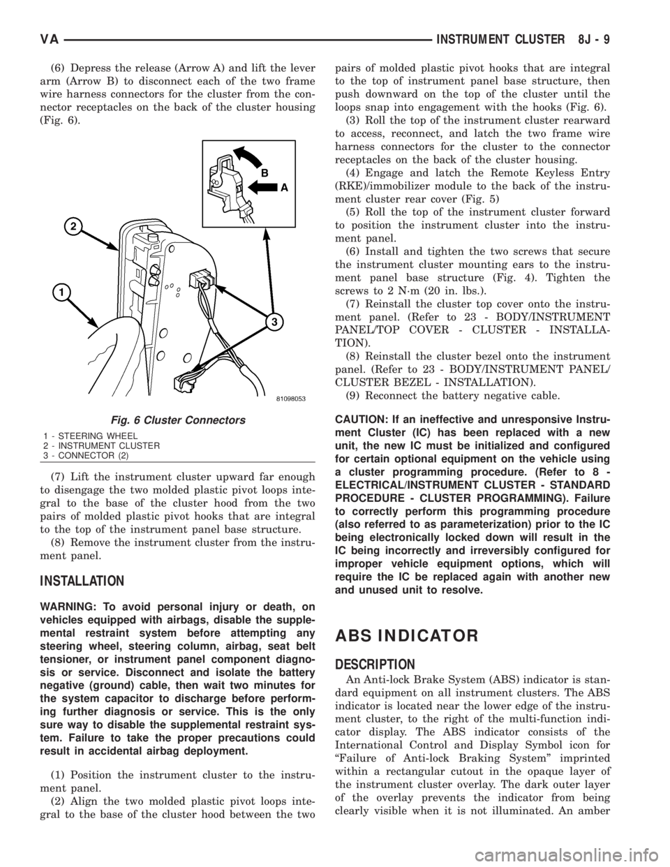
(6) Depress the release (Arrow A) and lift the lever
arm (Arrow B) to disconnect each of the two frame
wire harness connectors for the cluster from the con-
nector receptacles on the back of the cluster housing
(Fig. 6).
(7) Lift the instrument cluster upward far enough
to disengage the two molded plastic pivot loops inte-
gral to the base of the cluster hood from the two
pairs of molded plastic pivot hooks that are integral
to the top of the instrument panel base structure.
(8) Remove the instrument cluster from the instru-
ment panel.
INSTALLATION
WARNING: To avoid personal injury or death, on
vehicles equipped with airbags, disable the supple-
mental restraint system before attempting any
steering wheel, steering column, airbag, seat belt
tensioner, or instrument panel component diagno-
sis or service. Disconnect and isolate the battery
negative (ground) cable, then wait two minutes for
the system capacitor to discharge before perform-
ing further diagnosis or service. This is the only
sure way to disable the supplemental restraint sys-
tem. Failure to take the proper precautions could
result in accidental airbag deployment.
(1) Position the instrument cluster to the instru-
ment panel.
(2) Align the two molded plastic pivot loops inte-
gral to the base of the cluster hood between the twopairs of molded plastic pivot hooks that are integral
to the top of instrument panel base structure, then
push downward on the top of the cluster until the
loops snap into engagement with the hooks (Fig. 6).
(3) Roll the top of the instrument cluster rearward
to access, reconnect, and latch the two frame wire
harness connectors for the cluster to the connector
receptacles on the back of the cluster housing.
(4) Engage and latch the Remote Keyless Entry
(RKE)/immobilizer module to the back of the instru-
ment cluster rear cover (Fig. 5)
(5) Roll the top of the instrument cluster forward
to position the instrument cluster into the instru-
ment panel.
(6) Install and tighten the two screws that secure
the instrument cluster mounting ears to the instru-
ment panel base structure (Fig. 4). Tighten the
screws to 2 N´m (20 in. lbs.).
(7) Reinstall the cluster top cover onto the instru-
ment panel. (Refer to 23 - BODY/INSTRUMENT
PANEL/TOP COVER - CLUSTER - INSTALLA-
TION).
(8) Reinstall the cluster bezel onto the instrument
panel. (Refer to 23 - BODY/INSTRUMENT PANEL/
CLUSTER BEZEL - INSTALLATION).
(9) Reconnect the battery negative cable.
CAUTION: If an ineffective and unresponsive Instru-
ment Cluster (IC) has been replaced with a new
unit, the new IC must be initialized and configured
for certain optional equipment on the vehicle using
a cluster programming procedure. (Refer to 8 -
ELECTRICAL/INSTRUMENT CLUSTER - STANDARD
PROCEDURE - CLUSTER PROGRAMMING). Failure
to correctly perform this programming procedure
(also referred to as parameterization) prior to the IC
being electronically locked down will result in the
IC being incorrectly and irreversibly configured for
improper vehicle equipment options, which will
require the IC be replaced again with another new
and unused unit to resolve.
ABS INDICATOR
DESCRIPTION
An Anti-lock Brake System (ABS) indicator is stan-
dard equipment on all instrument clusters. The ABS
indicator is located near the lower edge of the instru-
ment cluster, to the right of the multi-function indi-
cator display. The ABS indicator consists of the
International Control and Display Symbol icon for
ªFailure of Anti-lock Braking Systemº imprinted
within a rectangular cutout in the opaque layer of
the instrument cluster overlay. The dark outer layer
of the overlay prevents the indicator from being
clearly visible when it is not illuminated. An amber
Fig. 6 Cluster Connectors
1 - STEERING WHEEL
2 - INSTRUMENT CLUSTER
3 - CONNECTOR (2)
VAINSTRUMENT CLUSTER 8J - 9
Page 963 of 2305
ADJUSTMENTS
ADJUSTMENT - FRONT LAMP UNIT
VEHICLE PREPARATION FOR FRONT LAMP UNIT
ALIGNMENT
(1) Verify headlamp dimmer (multi-function)
switch, fog lamp switch (if equipped), and high beam
indicator operation.
(2) Verify that the headlamp leveling switch is in
the ª0º position.
(3) Repair or replace any faulty or damaged com-
ponents that could interfere with proper lamp align-
ment.
(4) Verify proper tire inflation.
(5) Clean front lamp unit lenses.
(6) Verify that the cargo compartment is not
heavily loaded. Vehicle should be at or near curb
weight.
(7) The fuel tank should be ªFull.º Add 2.94 kilo-
grams (6.5 pounds) of weight over the fuel tank for
each estimated gallon of missing fuel.
(8) Load the driver's seat with 75 kilograms (165
pounds) of weight.
FRONT LAMP UNIT ALIGNMENT
(1) Position the vehicle on a level surface.
(2) Turn On the headlamp low beams or the fog
lamps (if equipped).
(3) Open the hood.
(4) Set up the headlamp adjuster according to the
instructions provided by the manufacturer of the
unit.
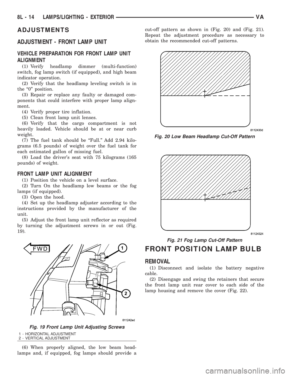
(5) Adjust the front lamp unit reflector as required
by turning the adjustment screws in or out (Fig.
19).
(6) When properly aligned, the low beam head-
lamps and, if equipped, fog lamps should provide acut-off pattern as shown in (Fig. 20) and (Fig. 21).
Repeat the adjustment procedure as necessary to
obtain the recommended cut-off patterns.
FRONT POSITION LAMP BULB
REMOVAL
(1) Disconnect and isolate the battery negative
cable.
(2) Disengage and swing the retainers that secure
the front lamp unit rear cover to each side of the
lamp housing and remove the cover (Fig. 22).
Fig. 19 Front Lamp Unit Adjusting Screws
1 - HORIZONTAL ADJUSTMENT
2 - VERTICAL ADJUSTMENT
Fig. 20 Low Beam Headlamp Cut-Off Pattern
Fig. 21 Fog Lamp Cut-Off Pattern
8L - 14 LAMPS/LIGHTING - EXTERIORVA