Page 747 of 2305

DRIVELINE VIBRATION
Drive Condition Possible Cause Correction
Propeller Shaft Noise 1) Undercoating or other foreign
material on shaft.1) Clean exterior of shaft and wash
with solvent.
2) Loose U-joint clamp screws. 2) Install new clamps and screws
and tighten to proper torque.
3) Loose or bent U-joint yoke or
excessive runout.3) Install new yoke.
4) Incorrect driveline angularity. 4) Measure and correct driveline
angles.
5) Rear spring center bolt not in
seat.5) Loosen spring u-bolts and seat
center bolt.
6) Worn U-joint bearings. 6) Install new U-joint.
7) Propeller shaft damaged or out
of balance.7) Installl new propeller shaft.
8) Broken rear spring. 8) Install new rear spring.
9) Excessive runout or unbalanced
condition.9) Re-index propeller shaft, test,
and evaluate.
10) Excessive drive pinion gear
shaft runout.10) Re-index propeller shaft and
evaluate.
11) Excessive axle yoke deflection. 11) Inspect and replace yoke if
necessary.
12) Excessive transfer case
runout.12) Inspect and repair as neces-
sary.
Universal Joint Noise 1) Loose U-joint clamp screws. 1) Install new clamps and screws
and tighten to proper torque.
2) Lack of lubrication. 2) Replace as U-joints as neces-
sary.
PROPELLER SHAFT BALANCE
NOTE: Removing and indexing the propeller shaft
180É relative to the yoke may eliminate some vibra-
tions.
If propeller shaft is suspected of being out of bal-
ance, verify with the following procedure:
(1) Place vehicle in netrual.
(2) Raise and support the vehicle by the axles as
level as possible.
(3) Clean all foreign material from propeller shaft
and universal joints.
(4) Inspect propeller shaft for missing balance
weights, broken welds, and bent areas.
NOTE: If propeller shaft is bent, it must be replaced.
(5) Inspect universal joints for wear, properly
installed and correct alignment with the shaft.
(6) Check universal joint clamp screws torque.
(7) Remove wheels and tires. Install wheel lug
nuts to retain the brake drums/rotors.(8) Mark and number propeller shaft six inches
from the pinion yoke end at four positions 90É apart.
(9) Run and accelerate the vehicle until vibration
occurs. Note intensity and speed the vibration
occurred. Stop the engine.
(10) Install a screw clamp at position 1 (Fig. 1).
3 - 2 PROPELLER SHAFTVA
Page 752 of 2305
PROPELLER SHAFT
REMOVAL
(1) Secure vehicle to prevent it from rolling.
(2) Make installing reference marks on propeller
shaft (Fig. 6) and (Fig. 7).
(3) Remove retaining bracket bolts (Fig. 8) and
(Fig. 9).
(4) Remove propeller shaft bolts from rear axle
and transmission at the flange.
(5) Remove propeller shaft intermediate bearing
nuts from retaining bracket and bracket for brake
cable.
NOTE: The brake cable bracket is only installed in
vehicles with wheelbase 3550 mm
SPLITTER 1130
INSTALLER 9275
INCLINOMETER 7663
Fig. 6 ALIGNMENT MARKS
1 - ALIGNMENT MARK
2 - BOOT
3 - ALIGNMENT MARK
4 - CENTER BEARING
Fig. 7 ALIGNMENT MARKS 3 PIECE SHAFT
1 - REFERNCE MARK
2 - CENTER SHAFT
3 - REFERENCE MARK
4 - REAR SHAFT
VAPROPELLER SHAFT 3 - 7
Page 754 of 2305

(6) Remove shaft from the vehicle.
INSTALLATION
(1) Install propeller shaft intermediate bearing/
bearings to support and tighten nuts to 105 N´m (77
ft. lbs.).
(2) Install propeller shaft intermediate bearing
support/supports to frame floor and tighten bolts to
95 N´m (70 ft. lbs.).
(3) Install propeller shaft intermediate bearing
with retaining bracket and bracket for brake cable.
NOTE: The bracket is only installed on vehicles
with wheelbase 3550 mm.
(4) Install propeller shaft to rear axle and trans-
mission flange with installation marks are aligned.
Tighten bolts to 70 N´m (66 ft. lbs.).
(5) Install retaining bracket and tighten bolts to
100 N´m (74 ft. lbs.).
CENTER BEARING
REMOVAL
(1) Remove propeller shaft.
(2) Mark shafts for installation alignment (Fig.
10).(3) Loosen both collar clamps (Fig. 11).
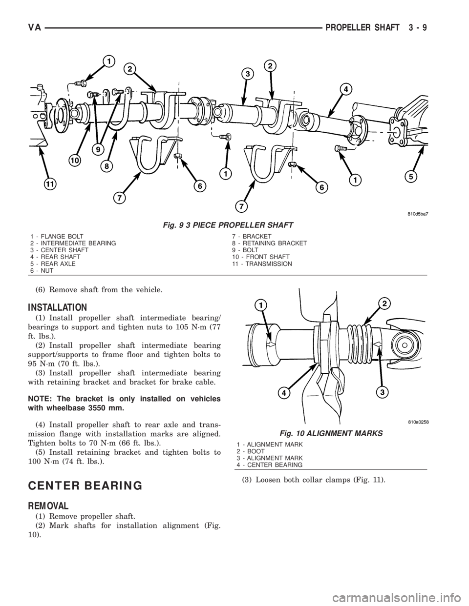
Fig. 9 3 PIECE PROPELLER SHAFT
1 - FLANGE BOLT 7 - BRACKET
2 - INTERMEDIATE BEARING 8 - RETAINING BRACKET
3 - CENTER SHAFT 9 - BOLT
4 - REAR SHAFT 10 - FRONT SHAFT
5 - REAR AXLE 11 - TRANSMISSION
6 - NUT
Fig. 10 ALIGNMENT MARKS
1 - ALIGNMENT MARK
2 - BOOT
3 - ALIGNMENT MARK
4 - CENTER BEARING
VAPROPELLER SHAFT 3 - 9
Page 760 of 2305

(1) Raise and support the vehicle.
(2) Position a suitable lifting device under the axle
and secure axle to device.
(3) Remove wheels and tires.
(4) Unplug wear indicator cable (Fig. 2) and (Fig.
3).
(5) Detach cable connector for brake pad wear
indicator.
(6) Remove ABS sensor and clamp bushing from
mounting bore.
NOTE: The right-hand ABS sensor cable is labeled
at the factory with a white tag.
(7) Remove cable ties from the park brake cables.
Release connection cable of brake pad wear indicator
and ABS sensor cable up to the relay unit of the
parking brake.
(8) Remove brake cables.
(9) Remove hand brake cable at relay unit.(10) Remove bracket for brake cables at rear axle
tube.
(11) Remove stabilizer bar from axle brackets.
(12) Remove shock absorber bolts from rear axle.
(13) Remove ALB lever from rear axle bracket.
(14) Pull vent line of rear axle out of frame.
(15) Remove propeller shaft.
(16) Remove brake calipers.
(17) Remove U-brackets and plates (Fig. 2) and
(Fig. 3).
(18) Remove axle from the vehicle.
Fig. 3 DUAL REAR WHEEL AXLE
1 - SPRING 12 - BRAKE HOSE
2 - SPRING SHACKLE 13 - LUG NUT
3 - PLATE 14 - NUT
4 - COLLAR NUT 15 - WASHER
5 - BRAKE CABLE 16 - BOLT
6 - REAR AXLE 17 - SHOCK ABSORBER
7 - ALB LEVER 18 - PROPELLER SHAFT
8 - NUT 19 - BOLT
9 - BOLT 20 - ABS SENSOR
10 - WEAR INDICATOR CABLE 21 - SENSOR BUSHING
11 - WEAR INDICATOR CONNECTOR
VAREAR AXLE 3 - 15
Page 762 of 2305

(1) Raise axle into position.
(2) Install plates and U-brackets (Fig. 4) and (Fig.
5) withnewnuts. Tighten nuts to 170 N´m (125 ft.
lbs.).
(3) Install propeller shaft and tighten bolts to 70
N´m (52 ft. lbs.).
NOTE: On installation of the propeller shaft, joint
arrows must be flush and must point towards the
frame floor. Tighten the propeller shaft in this posi-
tion.
(4) Install ALB lever to axle bracket and tighten
newnut 34 N´m (46 ft. lbs.).
(5) Install shock absorbers to rear axle and tighten
bolts to:
²M12 x 1.5 Bolt - 70 N´m (52 ft. lbs.)
²M14 x 1.5 Bolt - 110 N´m (81 ft. lbs.)
(6) Install stabilizer bar to axle and tighten bolts
to:
²SRW Axle - 25 N´m (18 ft. lbs.)²DRW Axle - 70 N´m (52 ft. lbs.)
(7) Install calipers with adapters and lines.
(8) Install brake hoses and hold-down clips.
(9) Install and adjust park brake cables.
(10) Install connection cable of brake pad wear
indicator and ABS sensor cable up to the relay unit
of the parking brake.
(11) Install cable ties to the park brake cables.
(12) Install ABS sensor and clamp bushing to
mounting bore.
NOTE: The right-hand ABS sensor cable is labeled
at the factory with a white tag.
(13) Attach connector cable for brake pad wear
indicator.
(14) Plug in cable of brake pad wear indicator.
(15) Install the wheels and tires.
(16) Fill axle with appropriate lubricant.
(17) Remove lifting device from under the axle.
(18) Remove support and lower vehicle.
Fig. 5 DUAL REAR WHEEL AXLE
1 - SPRING 12 - BRAKE HOSE
2 - SPRING SHACKLE 13 - LUG NUT
3 - PLATE 14 - NUT
4 - COLLAR NUT 15 - WASHER
5 - BRAKE CABLE 16 - BOLT
6 - REAR AXLE 17 - SHOCK ABSORBER
7 - ALB LEVER 18 - PROPELLER SHAFT
8 - NUT 19 - BOLT
9 - BOLT 20 - ABS SENSOR
10 - WEAR INDICATOR CABLE 21 - SENSOR BUSHING
11 - WEAR INDICATOR CONNECTOR
VAREAR AXLE 3 - 17
Page 768 of 2305
SHAFT - AXLE SINGLE REAR WHEEL
REMOVAL-SINGLE REAR WHEEL
(1) Remove wheels.
(2) Detach front brake cable.
(3) Pull ABS sensor (18) together with clamp bush-
ing (19) out of bearing cap (Fig. 6).
(4) Remove brake caliper (16) and disk (10) at rear
axle (14). Attach brake caliper with lines connected
in wheel house.
(5) Remove brake shoes (2) of parking brake.
(6) Remove brake control cable lock.
(7) Remove bearing cap bolts (17) and pull axle
shaft out of axle tube (1) (Fig. 6).
(8) Remove seal/gasket.
Fig. 6 AXLE SHAFT
1 - REAR AXLE 11 - BOLT
2 - BRAKE SHOE 12 - WHEEL BOLT
3 - PRESSURE SPRING 13 - BRAKE ADJUSTER
4 - RETURN SPRING 14 - REAR AXLE SHAFT
5 - RETURN SPRING 15 - GASKET
6 - CABLE LOCK 16 - BRAKE CABLE
7 - PARK BRAKE CABLE 17 - BOLT
8 - LOCKING PIN 18 - ABS SENSOR
9 - BOLT 19 - SENSOR BUSHING
10 - BRAKE DISC
VAREAR AXLE 3 - 23
Page 769 of 2305

INSTALLATION - SINGLE REAR WHEEL
(1) Install sealing ring.
(2) Install axle shaft (1) in the axle tube (2) (Fig.
7).
(3) Installnewbearing cap (2) bolts (1) and
tighten to 72 N´m (53 ft. lbs.) (Fig. 8).
NOTE: Tighten bolts diagonally across.
(4) Install brake control cable lock.
(5) Install parking brake shoes.
(6) Install brake disk and calipers.
(7) Coat clamping bush with acid-free grease.
Insert ABS sensor with clamping bush fully into the
mounting hole.
(8) Install front brake cable.(9) Operate brake pedal several times until brake
pads contact brake discs (brake pressure built up).
(10) Install wheels.
BEARING / SEAL - AXLE
REMOVAL
(1) Remove rear axle shaft.
(2) With a punch (2) and hammer straighten bear-
ing (4) nut (1) locking ring (3) (Fig. 9).
(3) Install two wheel mounting bolts into the axle
shaft (1) and clamp in vise. Loosen bearing (4) nut
(2) with Wrench 9279 (3) (Fig. 10).
Fig. 7 AXLE SHAFT AND TUBE
1 - AXLE SHAFT
2 - AXLE TUBE
3 - AXLE BEARINGS
4 - DUST SHIELD
Fig. 8 BEARING CAP BOLTS
1 - BEARING CAP BOLTS
2 - BEARING CAP
3 - AXLE SHAFT FLANGE
Fig. 9 LOCKING RING
1 - BEARING NUT
2 - PUNCH
3 - LOCKING RING
4 - BEARING
Fig. 10 BEARING NUT WRENCH
1 - AXLE SHAFT
2 - BEARING NUT
3 - WRENCH
4 - BEARING
3 - 24 REAR AXLEVA
Page 777 of 2305
DISASSEMBLY
DISASSEMBLY - SINGLE REAR WHEEL
(1) Remove differential cover bolts and remove
cover (Fig. 33).
(2) Remove upper differential side gear (1) and
shim (2) (Fig. 34).(3) Remove first set of differential pinion gears (1),
spherical washers and mate shaft (2) (Fig. 35).
(4) Remove second set of differential pinion gears
(2), spherical washers and mate shaft (1) (Fig. 36).
Fig. 33 DIFFERENTIAL COVER
1 - BOLTS
2 - COVER
Fig. 34 UPPER SIDE GEAR
1 - SIDE GEAR
2 - SHIM
Fig. 35 FIRST PINION GEARS
1 - PINION GEARS
2 - MATE SHAFT
Fig. 36 SECOND PINION GEAR SET
1 - MATE SHAFT
2 - PINION GEARS
3 - 32 REAR AXLEVA