2006 MERCEDES-BENZ SPRINTER wheel bolts
[x] Cancel search: wheel boltsPage 1597 of 2305
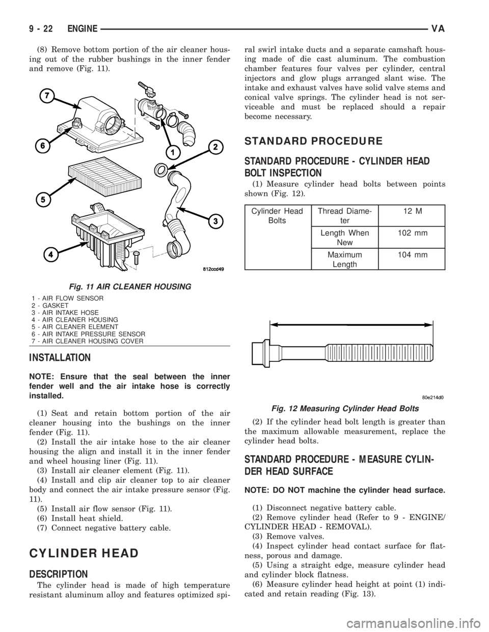
(8) Remove bottom portion of the air cleaner hous-
ing out of the rubber bushings in the inner fender
and remove (Fig. 11).
INSTALLATION
NOTE: Ensure that the seal between the inner
fender well and the air intake hose is correctly
installed.
(1) Seat and retain bottom portion of the air
cleaner housing into the bushings on the inner
fender (Fig. 11).
(2) Install the air intake hose to the air cleaner
housing the align and install it in the inner fender
and wheel housing liner (Fig. 11).
(3) Install air cleaner element (Fig. 11).
(4) Install and clip air cleaner top to air cleaner
body and connect the air intake pressure sensor (Fig.
11).
(5) Install air flow sensor (Fig. 11).
(6) Install heat shield.
(7) Connect negative battery cable.
CYLINDER HEAD
DESCRIPTION
The cylinder head is made of high temperature
resistant aluminum alloy and features optimized spi-ral swirl intake ducts and a separate camshaft hous-
ing made of die cast aluminum. The combustion
chamber features four valves per cylinder, central
injectors and glow plugs arranged slant wise. The
intake and exhaust valves have solid valve stems and
conical valve springs. The cylinder head is not ser-
viceable and must be replaced should a repair
become necessary.
STANDARD PROCEDURE
STANDARD PROCEDURE - CYLINDER HEAD
BOLT INSPECTION
(1) Measure cylinder head bolts between points
shown (Fig. 12).
Cylinder Head
BoltsThread Diame-
ter12 M
Length When
New102 mm
Maximum
Length104 mm
(2) If the cylinder head bolt length is greater than
the maximum allowable measurement, replace the
cylinder head bolts.
STANDARD PROCEDURE - MEASURE CYLIN-
DER HEAD SURFACE
NOTE: DO NOT machine the cylinder head surface.
(1) Disconnect negative battery cable.
(2) Remove cylinder head (Refer to 9 - ENGINE/
CYLINDER HEAD - REMOVAL).
(3) Remove valves.
(4) Inspect cylinder head contact surface for flat-
ness, porous and damage.
(5) Using a straight edge, measure cylinder head
and cylinder block flatness.
(6) Measure cylinder head height at point (1) indi-
cated and retain reading (Fig. 13).
Fig. 11 AIR CLEANER HOUSING
1 - AIR FLOW SENSOR
2 - GASKET
3 - AIR INTAKE HOSE
4 - AIR CLEANER HOUSING
5 - AIR CLEANER ELEMENT
6 - AIR INTAKE PRESSURE SENSOR
7 - AIR CLEANER HOUSING COVER
Fig. 12 Measuring Cylinder Head Bolts
9 - 22 ENGINEVA
Page 1616 of 2305
CAUTION: Oil thread and head contact surfaces of
bolts that retain the crankshaft bearing caps;
tighten bolts from inside to outside, beginning at
the fit bearing. Rotate crankshaft to check clear-
ance.
(1) Install crankshaft.
CAUTION: The crankshaft bearing caps are num-
bered consecutively, beginning with the first crank-
shaft bearing cap at the front of the engine.
Attention must be paid to the way the crankshaft
bearing caps fit. If correctly installed, the lug, or
raised boss, on the crankshaft bearing cap is point-
ing to the left when viewed in the direction of travel
(intake side).
(2) Install the crankshaft bearing caps. Tighten
bolts in two stages. 55N´m (40.5 lbs. ft.), then 90É.
(3) Install the pistons (Refer to 9 - ENGINE/EN-
GINE BLOCK/PISTON & CONNECTING ROD -
INSTALLATION).
(4) Install the end cover (Refer to 9 - ENGINE/EN-
GINE BLOCK/CRANKSHAFT OIL SEAL - REAR -
INSTALLATION).
(5) Install the timing case cover (Refer to 9 -
ENGINE/VALVE TIMING/TIMING BELT / CHAIN
COVER(S) - INSTALLATION).
(6) Install the engine (Refer to 9 - ENGINE -
INSTALLATION).
(7) Fill the crankcase with the correct engine oil,
to the proper level. Refer to the owners manual for
specifications.
(8) Fill the cooling system with the proper coolant,
to the proper level (Refer to 7 - COOLING/ENGINE/
COOLANT - STANDARD PROCEDURE).
(9) Connect the negative battery cable.
WARNING: USE EXTREME CAUTION WHEN THE
ENGINE IS OPERATING. DO NOT STAND IN A
DIRECT LINE WITH THE FAN. DO NOT PUT YOUR
HANDS NEAR THE PULLEYS, BELTS, OR FAN. DO
NOT WEAR LOOSE CLOTHES.
(10) Start engine and inspect for leaks. Care must
be taken to observe the fuel system warning (Refer to
14 - FUEL SYSTEM - WARNING).
CRANKSHAFT OIL SEAL -
REAR
REMOVAL
This must be done with the transmission removed
from the vehicle.
(1) Disconnect the negative battery cable.
(2) Raise and support the vehicle.
(3) Drain the engine oil.NOTE: Loosen all of the oil pan bolts to assure that
the oil pan gasket is not damaged when removing
the rear main oil seal and end cover assembly.
NOTE: Inspect the oil pan gasket for damage. If the
oil pan gasket is damaged, remove the oil pan and
replace the oil pan gasket.
(4) Loosen the oil pan bolts.
(5) Remove the flywheel.
CAUTION: Care must be taken when removing the
rear main seal and adaptor assembly. Failure to do
so will result in damage to the oil pan gasket.
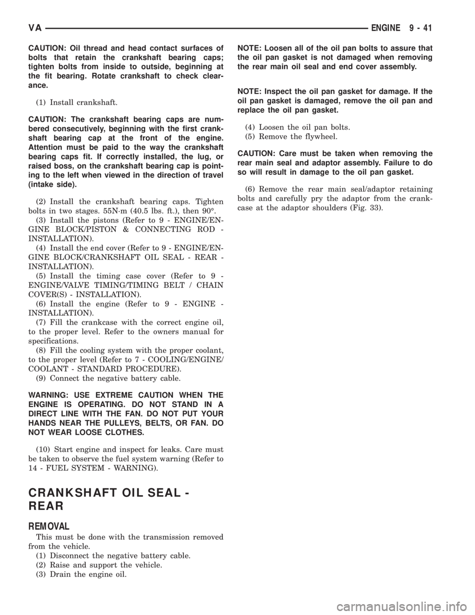
(6) Remove the rear main seal/adaptor retaining
bolts and carefully pry the adaptor from the crank-
case at the adaptor shoulders (Fig. 33).
VAENGINE 9 - 41
Page 1617 of 2305
INSTALLATION
NOTE: Thoroughly clean all mating surfaces with
the appropriate solvents to assure that no grease or
oil is present during reassembly.
NOTE: Carefully position the rear main seal/adaptor
evenly onto the assembly sleeve. The rear main oil
seal lip MUST NOT roll over the edge of the tool.
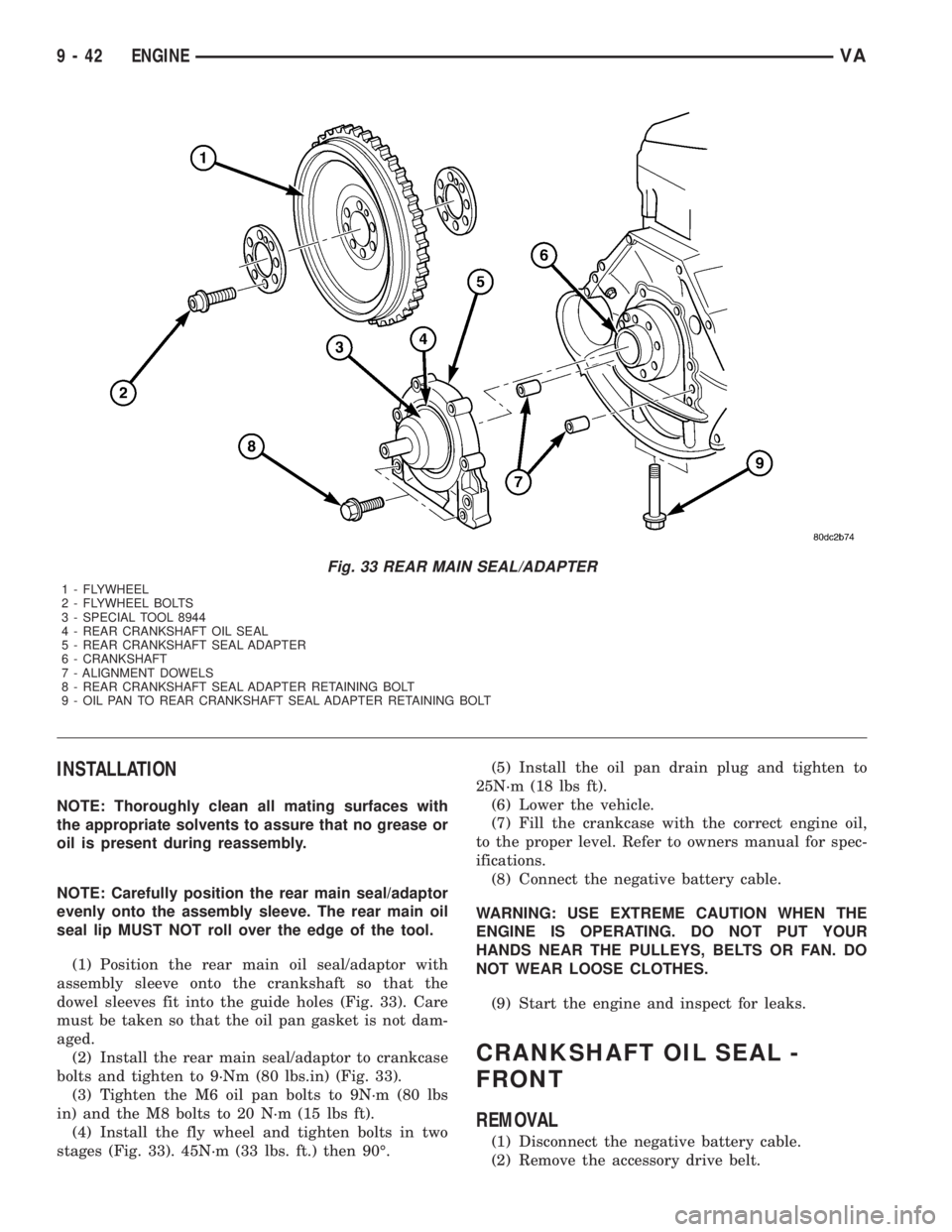
(1) Position the rear main oil seal/adaptor with
assembly sleeve onto the crankshaft so that the
dowel sleeves fit into the guide holes (Fig. 33). Care
must be taken so that the oil pan gasket is not dam-
aged.
(2) Install the rear main seal/adaptor to crankcase
bolts and tighten to 9´Nm (80 lbs.in) (Fig. 33).
(3) Tighten the M6 oil pan bolts to 9N´m (80 lbs
in) and the M8 bolts to 20 N´m (15 lbs ft).
(4) Install the fly wheel and tighten bolts in two
stages (Fig. 33). 45N´m (33 lbs. ft.) then 90É.(5) Install the oil pan drain plug and tighten to
25N´m (18 lbs ft).
(6) Lower the vehicle.
(7) Fill the crankcase with the correct engine oil,
to the proper level. Refer to owners manual for spec-
ifications.
(8) Connect the negative battery cable.
WARNING: USE EXTREME CAUTION WHEN THE
ENGINE IS OPERATING. DO NOT PUT YOUR
HANDS NEAR THE PULLEYS, BELTS OR FAN. DO
NOT WEAR LOOSE CLOTHES.
(9) Start the engine and inspect for leaks.
CRANKSHAFT OIL SEAL -
FRONT
REMOVAL
(1) Disconnect the negative battery cable.
(2) Remove the accessory drive belt.
Fig. 33 REAR MAIN SEAL/ADAPTER
1 - FLYWHEEL
2 - FLYWHEEL BOLTS
3 - SPECIAL TOOL 8944
4 - REAR CRANKSHAFT OIL SEAL
5 - REAR CRANKSHAFT SEAL ADAPTER
6 - CRANKSHAFT
7 - ALIGNMENT DOWELS
8 - REAR CRANKSHAFT SEAL ADAPTER RETAINING BOLT
9 - OIL PAN TO REAR CRANKSHAFT SEAL ADAPTER RETAINING BOLT
9 - 42 ENGINEVA
Page 1618 of 2305
(3) Install the retaining lock for the crankshaft/
ring gear.
NOTE: If the hub of the belt pulley/vibration damper
is tight, use a puller to remove it. Do Not tilt the
puller. The groves of the puller MUST mesh fully
into the slots of the belt pulley.
NOTE: Inspect the running surface of the belt pulley
for wear.
(4) Remove the belt pully/vibration damper.
CAUTION: Care must be taken to prevent severe
damage to the crankshaft and mounting whole for
the front crankshaft seal.
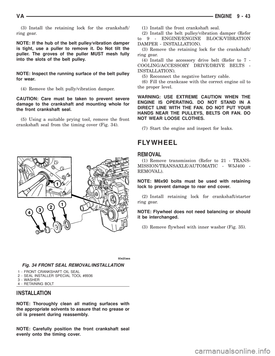
(5) Using a suitable prying tool, remove the front
crankshaft seal from the timing cover (Fig. 34).
INSTALLATION
NOTE: Thoroughly clean all mating surfaces with
the appropriate solvents to assure that no grease or
oil is present during reassembly.
NOTE: Carefully position the front crankshaft seal
evenly onto the timing cover.(1) Install the front crankshaft seal.
(2) Install the belt pulley/vibration damper (Refer
to 9 - ENGINE/ENGINE BLOCK/VIBRATION
DAMPER - INSTALLATION).
(3) Remove the retaining lock for the crankshaft/
ring gear.
(4) Install the accessory drive belt (Refer to 7 -
COOLING/ACCESSORY DRIVE/DRIVE BELTS -
INSTALLATION).
(5) Reconnect the negative battery cable.
(6) Fill the crankcase with the correct engine oil to
the proper level.
WARNING: USE EXTREME CAUTION WHEN THE
ENGINE IS OPERATING. DO NOT STAND IN A
DIRECT LINE WITH THE FAN. DO NOT PUT YOUR
HANDS NEAR THE PULLEYS, BELTS OR FAN. DO
NOT WEAR LOOSE CLOTHES.
(7) Start the engine and inspect for leaks.
FLYWHEEL
REMOVAL
(1) Remove transmission (Refer to 21 - TRANS-
MISSION/TRANSAXLE/AUTOMATIC - W5J400 -
REMOVAL).
NOTE: M6x90 bolts must be used with retaining
lock to prevent damage to rear end cover.
(2) Install retaining lock for crankshaft/starter
ring gear.
NOTE: Flywheel does not need balancing or should
it be interchanged.
(3) Remove flywheel with inner washer (Fig. 35).
Fig. 34 FRONT SEAL REMOVAL/INSTALLATION
1 - FRONT CRANKSHAFT OIL SEAL
2 - SEAL INSTALLER SPECIAL TOOL #8936
3 - WASHER
4 - RETAINING BOLT
VAENGINE 9 - 43
Page 1619 of 2305
INSTALLATION
INSTALLATION
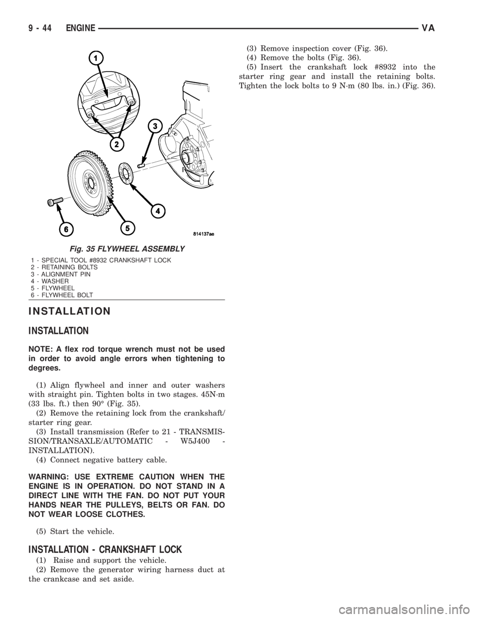
NOTE: A flex rod torque wrench must not be used
in order to avoid angle errors when tightening to
degrees.
(1) Align flywheel and inner and outer washers
with straight pin. Tighten bolts in two stages. 45N´m
(33 lbs. ft.) then 90É (Fig. 35).
(2) Remove the retaining lock from the crankshaft/
starter ring gear.
(3) Install transmission (Refer to 21 - TRANSMIS-
SION/TRANSAXLE/AUTOMATIC - W5J400 -
INSTALLATION).
(4) Connect negative battery cable.
WARNING: USE EXTREME CAUTION WHEN THE
ENGINE IS IN OPERATION. DO NOT STAND IN A
DIRECT LINE WITH THE FAN. DO NOT PUT YOUR
HANDS NEAR THE PULLEYS, BELTS OR FAN. DO
NOT WEAR LOOSE CLOTHES.
(5) Start the vehicle.
INSTALLATION - CRANKSHAFT LOCK
(1) Raise and support the vehicle.
(2) Remove the generator wiring harness duct at
the crankcase and set aside.(3) Remove inspection cover (Fig. 36).
(4) Remove the bolts (Fig. 36).
(5) Insert the crankshaft lock #8932 into the
starter ring gear and install the retaining bolts.
Tighten the lock bolts to 9 N´m (80 lbs. in.) (Fig. 36).
Fig. 35 FLYWHEEL ASSEMBLY
1 - SPECIAL TOOL #8932 CRANKSHAFT LOCK
2 - RETAINING BOLTS
3 - ALIGNMENT PIN
4 - WASHER
5 - FLYWHEEL
6 - FLYWHEEL BOLT
9 - 44 ENGINEVA
Page 1676 of 2305
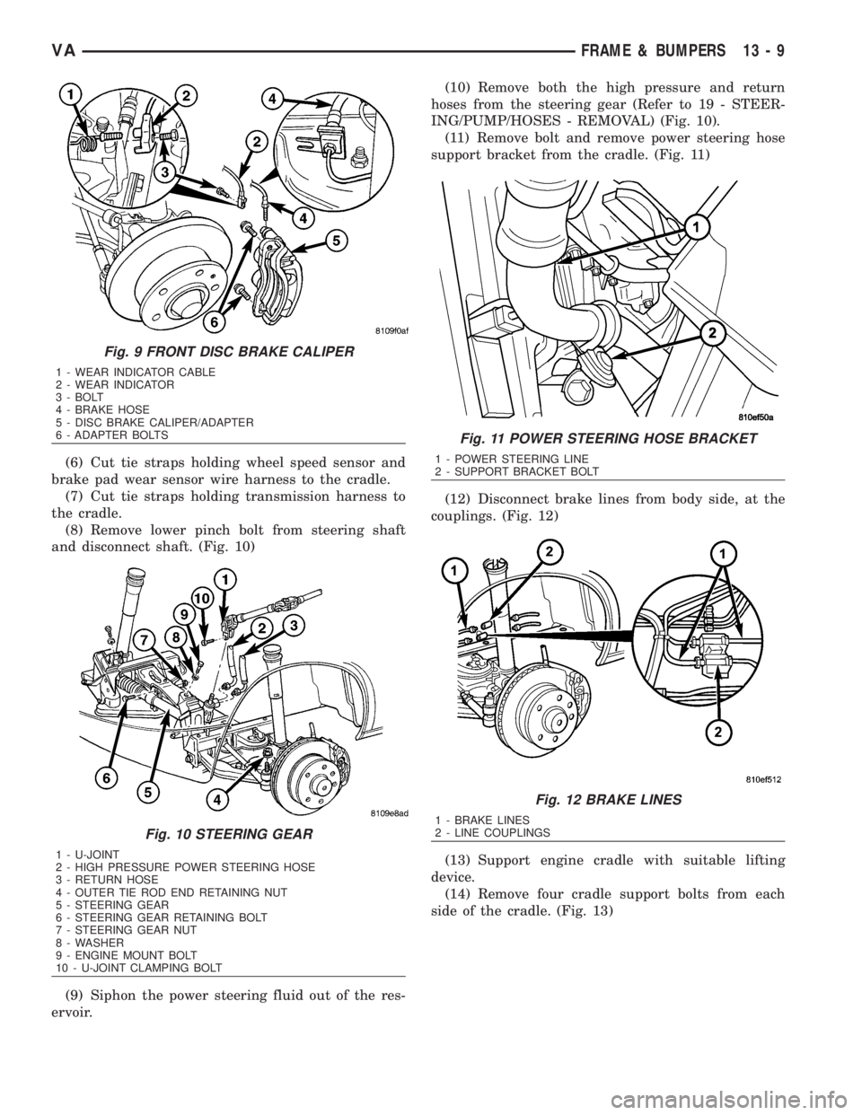
(6) Cut tie straps holding wheel speed sensor and
brake pad wear sensor wire harness to the cradle.
(7) Cut tie straps holding transmission harness to
the cradle.
(8) Remove lower pinch bolt from steering shaft
and disconnect shaft. (Fig. 10)
(9) Siphon the power steering fluid out of the res-
ervoir.(10) Remove both the high pressure and return
hoses from the steering gear (Refer to 19 - STEER-
ING/PUMP/HOSES - REMOVAL) (Fig. 10).
(11) Remove bolt and remove power steering hose
support bracket from the cradle. (Fig. 11)
(12) Disconnect brake lines from body side, at the
couplings. (Fig. 12)
(13) Support engine cradle with suitable lifting
device.
(14) Remove four cradle support bolts from each
side of the cradle. (Fig. 13)
Fig. 9 FRONT DISC BRAKE CALIPER
1 - WEAR INDICATOR CABLE
2 - WEAR INDICATOR
3 - BOLT
4 - BRAKE HOSE
5 - DISC BRAKE CALIPER/ADAPTER
6 - ADAPTER BOLTS
Fig. 10 STEERING GEAR
1 - U-JOINT
2 - HIGH PRESSURE POWER STEERING HOSE
3 - RETURN HOSE
4 - OUTER TIE ROD END RETAINING NUT
5 - STEERING GEAR
6 - STEERING GEAR RETAINING BOLT
7 - STEERING GEAR NUT
8 - WASHER
9 - ENGINE MOUNT BOLT
10 - U-JOINT CLAMPING BOLT
Fig. 11 POWER STEERING HOSE BRACKET
1 - POWER STEERING LINE
2 - SUPPORT BRACKET BOLT
Fig. 12 BRAKE LINES
1 - BRAKE LINES
2 - LINE COUPLINGS
VAFRAME & BUMPERS 13 - 9
Page 1678 of 2305
(18) Install calipers. (Refer to 5 - BRAKES/HY-
DRAULIC/MECHANICAL/DISC BRAKE CALIPERS
- INSTALLATION)
(19) Install new tie straps holding wheel speed
sensors and brake pad wear sensors wire harness to
cradle.
(20) Check and align vehicle to specifications.
(Refer to 2 - SUSPENSION/WHEEL ALIGNMENT -
STANDARD PROCEDURE)
REAR CROSSMEMBER -
TRANSMISSION
REMOVAL
(1) Raise and support the vehicle. (Refer to
LUBRICATION & MAINTENANCE/HOISTING -
STANDARD PROCEDURE)
(2) Support transmission with a suitable lifting
device.
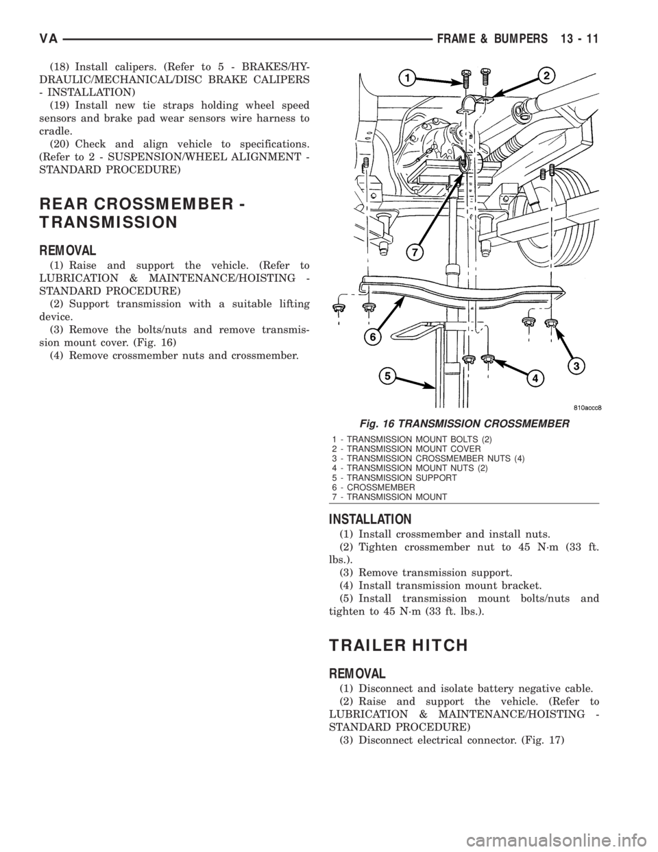
(3) Remove the bolts/nuts and remove transmis-
sion mount cover. (Fig. 16)
(4) Remove crossmember nuts and crossmember.
INSTALLATION
(1) Install crossmember and install nuts.
(2) Tighten crossmember nut to 45 N´m (33 ft.
lbs.).
(3) Remove transmission support.
(4) Install transmission mount bracket.
(5) Install transmission mount bolts/nuts and
tighten to 45 N´m (33 ft. lbs.).
TRAILER HITCH
REMOVAL
(1) Disconnect and isolate battery negative cable.
(2) Raise and support the vehicle. (Refer to
LUBRICATION & MAINTENANCE/HOISTING -
STANDARD PROCEDURE)
(3) Disconnect electrical connector. (Fig. 17)
Fig. 16 TRANSMISSION CROSSMEMBER
1 - TRANSMISSION MOUNT BOLTS (2)
2 - TRANSMISSION MOUNT COVER
3 - TRANSMISSION CROSSMEMBER NUTS (4)
4 - TRANSMISSION MOUNT NUTS (2)
5 - TRANSMISSION SUPPORT
6 - CROSSMEMBER
7 - TRANSMISSION MOUNT
VAFRAME & BUMPERS 13 - 11
Page 1730 of 2305
STEERING
TABLE OF CONTENTS
page page
STEERING
DESCRIPTION..........................1
OPERATION............................1
DIAGNOSIS AND TESTING - POWER
STEERING SYSTEM....................1COLUMN................................4
GEAR..................................7
LINKAGE................................9
PUMP..................................11
STEERING
DESCRIPTION
CAUTION: Use approved fluid only in the power
steering system (Refer to LUBRICATION & MAINTE-
NANCE/FLUID TYPES - DESCRIPTION). No other
power steering or automatic transmission fluid is to
be used in the system. Damage may result to the
power steering pump and system if any other fluid
is used, and do not overfill.
Power steering systems consist of:
²Steering column
²Rack and pinion steering gear
²Belt driven hydraulic steering pump
²Pump pressure and return hoses
²Oil Cooler
OPERATION
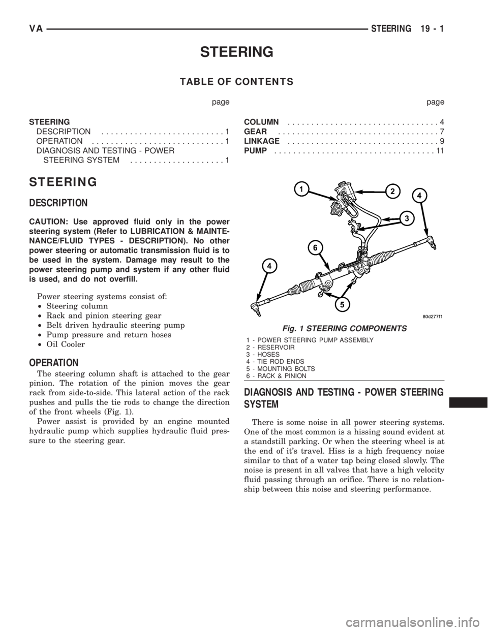
The steering column shaft is attached to the gear
pinion. The rotation of the pinion moves the gear
rack from side-to-side. This lateral action of the rack
pushes and pulls the tie rods to change the direction
of the front wheels (Fig. 1).
Power assist is provided by an engine mounted
hydraulic pump which supplies hydraulic fluid pres-
sure to the steering gear.
DIAGNOSIS AND TESTING - POWER STEERING
SYSTEM
There is some noise in all power steering systems.
One of the most common is a hissing sound evident at
a standstill parking. Or when the steering wheel is at
the end of it's travel. Hiss is a high frequency noise
similar to that of a water tap being closed slowly. The
noise is present in all valves that have a high velocity
fluid passing through an orifice. There is no relation-
ship between this noise and steering performance.
Fig. 1 STEERING COMPONENTS
1 - POWER STEERING PUMP ASSEMBLY
2 - RESERVOIR
3 - HOSES
4 - TIE ROD ENDS
5 - MOUNTING BOLTS
6 - RACK & PINION
VASTEERING 19 - 1