2006 MERCEDES-BENZ SPRINTER air conditioning
[x] Cancel search: air conditioningPage 846 of 2305

(17) Take off charge air cooler together with cool-
ing loop of the steering at the radiator (Fig. 10).
(18) Remove bottom radiator trim (Fig. 10).
(19) Detach coolant hose at radiator.
(20) Detach coolant pipe together with coolant
hose at the fan shroud.
(21) Remove radiator fan shroud (Fig. 10).
INSTALLATION
(1) Install fan shroud to radiator (Fig. 10).
(2) Attach coolant pipe with hoses to fan shroud
(Fig. 10).
(3) Attach coolant hose at radiator (Fig. 10).
(4) Install bottom radiator trim (Fig. 10).
(5) Install charge air cooler along with cooling loop
of the power steering, to radiator (Fig. 10).
(6) Install radiator assembly into the rubber grom-
mets (Fig. 9).
(7) Install both right and left side radiator trim
panels (Fig. 9).
(8) Attach the transmission cooler lines (Fig. 9).
(9) Attach coolant hose to the bottom right of the
radiator (Fig. 9).
(10) Attach both power steering hydraulic lines
(Fig. 9).
(11) Connect coolant level sensor electrical connec-
tor (Fig. 9).
(12) Connect coolant hoses to the coolant reservoir,
radiator and water pump (Fig. 9).(13) Attach air intake pipe at the body.
(14) Attach charge air hose at air intake.
(15) Attach charge air hose at turbocharger.
(16) Install A/C condenser.
(17) Install front bumper.
(18) Install front end cross member.
(19) Refill power steering to proper level.
(20) Refill transmission to proper level.
(21) Close radiator drain plug and refill the cooling
system (Refer to 7 - COOLING/ENGINE/COOLANT -
STANDARD PROCEDURE).
(22) Recharge air conditioning (Refer to 24 -
HEATING & AIR CONDITIONING/PLUMBING -
STANDARD PROCEDURE).
(23) Run engine until warm and check for leaks.
RADIATOR PRESSURE CAP
DESCRIPTION
All vehicles are equipped with a pressure cap (Fig.
11). This cap releases pressure at some point within
a range of 124-145 kPa (18-21 psi). The pressure
relief point (in pounds) is engraved on top of the cap
The cooling system will operate at pressures
slightly above atmospheric pressure. This results in a
higher coolant boiling point allowing increased radi-
ator cooling capacity. The cap contains a spring-
loaded pressure relief valve. This valve opens when
system pressure reaches the release range of 124-145
kPa (18-21 psi).
A rubber gasket seals the radiator filler neck. This
is done to maintain vacuum during coolant cool-down
and to prevent leakage when system is under pres-
sure.
Fig. 10 RADIATOR AND FAN SHROUD
1 - CLIP
2 - SHROUD
3 - RADIATOR
4 - BOTTOM RADIATOR TRIM PANEL
5 - CHARGE AIR COOLER
6 - TOP RADIATOR TRIM PANEL
7 - POWER STEERING COOLER LOOP
VAENGINE 7 - 19
Page 1080 of 2305
WIRING
TABLE OF CONTENTS
page page
WIRING DIAGRAM INFORMATION....... 8W-01-1
COMPONENT INDEX.................. 8W-02-1
POWER DISTRIBUTION............... 8W-10-1
FUSE BLOCK........................ 8W-11-1
GROUND DISTRIBUTION.............. 8W-15-1
BUS COMMUNICATIONS.............. 8W-18-1
CHARGING SYSTEM.................. 8W-20-1
STARTING SYSTEM.................. 8W-21-1
FUEL/IGNITION SYSTEM.............. 8W-30-1
TRANSMISSION CONTROL SYSTEM..... 8W-31-1
VEHICLE SPEED CONTROL............ 8W-33-1
ANTILOCK BRAKES................... 8W-35-1
VEHICLE THEFT SECURITY SYSTEM..... 8W-39-1
INSTRUMENT CLUSTER............... 8W-40-1
HORN/CIGAR LIGHTER................ 8W-41-1
AIR CONDITIONING-HEATER........... 8W-42-1
AIRBAG SYSTEM.................... 8W-43-1
INTERIOR LIGHTING.................. 8W-44-1CENTRAL TIMER MODULE............. 8W-45-1
AUDIO SYSTEM..................... 8W-47-1
REAR WINDOW DEFOGGER............ 8W-48-1
FRONT LIGHTING.................... 8W-50-1
REAR LIGHTING..................... 8W-51-1
TURN SIGNALS...................... 8W-52-1
WIPERS............................ 8W-53-1
TRAILER TOW....................... 8W-54-1
NAVIGATION/TELECOMMUNICATIONS.... 8W-55-1
POWER WINDOWS................... 8W-60-1
POWER DOOR LOCKS................ 8W-61-1
POWER MIRRORS................... 8W-62-1
POWER SEATS...................... 8W-63-1
SPLICE INFORMATION................ 8W-70-1
CONNECTOR PIN-OUTS............... 8W-80-1
CONNECTOR/GROUND/SPLICE
LOCATION........................ 8W-91-1
POWER DISTRIBUTION............... 8W-97-1 VAWIRING 8W - 1
Page 1290 of 2305
8W-42 AIR CONDITIONING-HEATER
Component Page
A/C Auxiliary Fan................... 8W-42-2
A/C Auxiliary Fan Relay............... 8W-42-2
A/C Compressor Clutch............ 8W-42-2, 23
A/C Compressor Clutch Relay......... 8W-42-23
A/C Roof Auxiliary Fan............... 8W-42-23
A/C Roof Auxiliary Fan Relay.......... 8W-42-23
Additional Heat Exchanger...... 8W-42-15, 16, 17
Additional Heat Exchanger Relay.... 8W-42-15, 16
Additional Heat Exchanger Switch . . . 8W-42-16, 17
Air Outlet Temperature Sensor......... 8W-42-4
Ambient Temperature Sensor........... 8W-42-3
Anti Icing Switch................... 8W-42-23
Automatic Temperature Control
Module . 8W-42-2, 3, 4, 5, 6, 7, 8, 9, 10, 11, 17, 19
Auxiliary Heater Control.......... 8W-42-10, 18
Blower Motor Resistor Block....... 8W-42-5, 6, 7
Blower Motor-Front.................. 8W-42-5
Blower Stage I Diode................ 8W-42-24
Cabin Heater Assembly............... 8W-42-9
Cabin Heater Module . . . 8W-42-8, 10, 11, 15, 18, 22
Circulation Pump.................... 8W-42-9
Circulation Pump Diode............ 8W-42-9, 11
Circulation Pump Relay-Cabin Heater
Module.......................... 8W-42-9
Controller Antilock Brake............. 8W-42-17
D+ Relay No. 1...................... 8W-42-3
Data Link Connector........... 8W-42-5, 10, 20
Daytime Running Lamps
Relay............ 8W-42-12, 13, 14, 17, 18, 19
Dosing Pump...................... 8W-42-11
Evaporator Temperature Sensor......... 8W-42-4
Fan Stage 1 Relay................... 8W-42-8
Fuse 1.......................... 8W-42-2, 22
Fuse 3............................ 8W-42-15
Fuse 4............................ 8W-42-11
Fuse 7............................ 8W-42-9
Fuse 8....................... 8W-42-8, 12, 18
Fuse 9............................ 8W-42-3
Fuse 11........................... 8W-42-20
Fuse 20....................... 8W-42-2, 9, 14
Fuse 21.......................... 8W-42-6, 7
Fuse 201.......................... 8W-42-24
Fuse 202.......................... 8W-42-24
Fuse 203.......................... 8W-42-23
Fuse 204.......................... 8W-42-23
Fuse Block No. 1............ 8W-42-2, 6, 7, 9, 18
Fuse Block No. 2.................... 8W-42-3
Fuse Block No. 3...... 8W-42-8, 11, 14, 15, 20, 22Component Page
Fuse/Relay Block................. 8W-42-2, 12
G100............................. 8W-42-11
G102.............................. 8W-42-2
G200.......................... 8W-42-3, 5, 9
G202................. 8W-42-2, 8, 9, 15, 16, 20
G203............. 8W-42-6, 7, 12, 14, 17, 18, 19
G301............................. 8W-42-12
G305....................... 8W-42-23, 24, 25
Heater Timer-Auxiliary.......... 8W-42-6, 7, 10,
17, 19, 21, 22
High Pressure Switch................ 8W-42-23
Instrument Cluster................... 8W-42-3
Interference Suppression Capacitor..... 8W-42-24
Low Pressure Switch................ 8W-42-23
Metering Pump..................... 8W-42-20
Optional Equipment Relay............ 8W-42-14
Power Distribution Center......... 8W-42-23, 24
Recirculated Air Solenoid Valve......... 8W-42-5
Refrigerant Pressure Sensor............ 8W-42-4
Rollover Switch..................... 8W-42-11
Rollover Switch Assembly.......... 8W-42-11, 15
Roof A/C Blower.................... 8W-42-24
Roof A/C Blower I................... 8W-42-24
Roof A/C Blower I Fuse.............. 8W-42-24
Roof A/C Blower Ii.................. 8W-42-24
Roof A/C Blower Ii Fuse.............. 8W-42-24
Roof A/C Blower Stage I And Ii Relay.... 8W-42-24
Roof A/C Blower Stage I Relay...... 8W-42-24, 25
Roof A/C Blower Stage Ii Relay...... 8W-42-12, 24
Roof A/C Compressor Fuse............ 8W-42-23
Roof A/C Control Module.......... 8W-42-12, 13
Roof A/C Fan Fuse.................. 8W-42-23
Roof A/C Switch................. 8W-42-10, 12
Roof A/C Temperature
Setting Control............. 8W-42-10, 13, 25
Roof Fan Motor..................... 8W-42-14
Roof Fan Switch................. 8W-42-10, 14
Roof Thermotronic Control
Module.............. 8W-42-12, 13, 23, 24, 25
Security System Module.............. 8W-42-20
TCS Switch........................ 8W-42-17
Temperature Sensor................. 8W-42-25
Thermotronic Diode................. 8W-42-23
Warm Air Auxiliary Control Module . . 8W-42-20, 21
Warm Air Auxiliary Heater
Assembly.................... 8W-42-20, 21
Water Cycle Valve................... 8W-42-3
VA8W-42 AIR CONDITIONING-HEATER 8W - 42 - 1
Page 1580 of 2305
REMOVAL
WARNING: NO SPARKS, OPEN FLAMES OR SMOK-
ING. RISK OF POISONING FROM INHALING AND
SWALLOWING FUEL. RISK OF INJURY TO EYES
AND SKIN FROM CONTACT WITH FUEL. POUR
FUELS ONLY INTO SUITABLE AND APPROPRI-
ATELY MARKED CONTAINERS. WEAR PROTECTIVE
CLOTHING.
WARNING: RISK OF INJURY TO SKIN AND EYES
FROM SCALDING WITH HOT COOLANT. RISK OF
POISONING FROM SWALLOWING COOLANT. DO
NOT OPEN COOLING SYSTEM UNLESS COOLANT
TEMPERATURE IS BELOW 90ÉC (194ÉF). OPEN CAP
SLOWLY TO RELEASE PRESSURE. STORE COOL-
ANT IN SUITABLE AND APPROPRIATELY MARKED
CONTAINER. WEAR PROTECTIVE GLOVES,
CLOTHES, AND EYE WEAR.
(1) Disconnect the negative battery cable.
NOTE: REPLACE THE AIR CONDITIONING DRIER
WHEN EVER THE AIR CONDITIONING SYSTEM IS
OPENED.
(2) Drain cooling system (Refer to 7 - COOLING/
ENGINE/COOLANT - STANDARD PROCEDURE).
(3) Evacuate and recover air conditioning system
(Refer to 24 - HEATING & AIR CONDITIONING/
PLUMBING - STANDARD PROCEDURE).
(4) Remove the front grille and fascia assembly.(5) Disconnect the engine wiring harness at the
cabin side and carefully guide though the cowl into
the engine area.
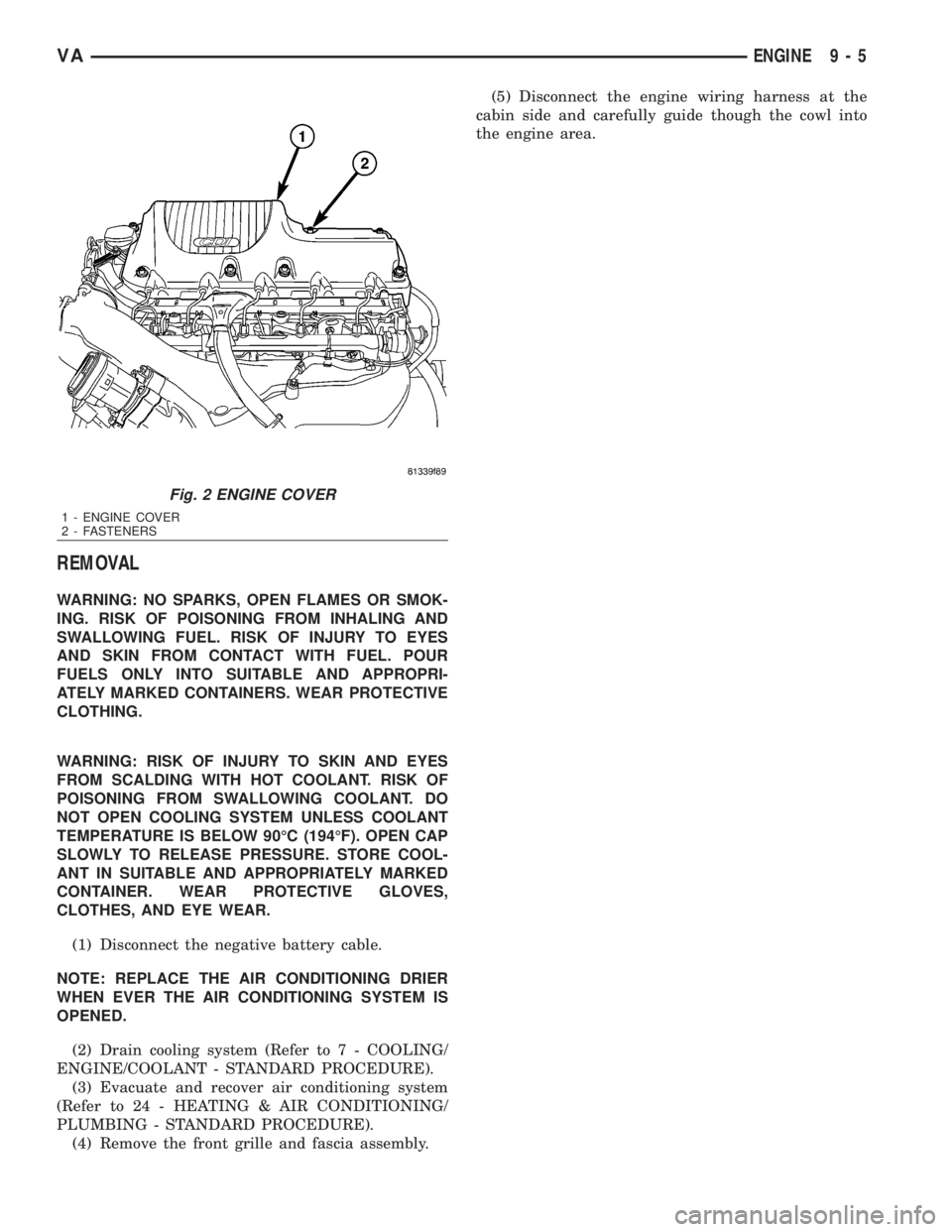
Fig. 2 ENGINE COVER
1 - ENGINE COVER
2 - FASTENERS
VAENGINE 9 - 5
Page 1583 of 2305
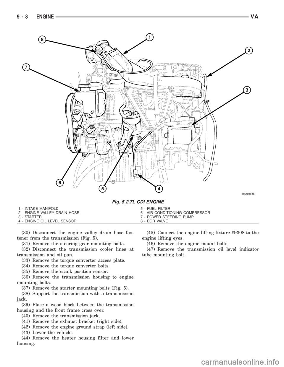
(30) Disconnect the engine valley drain hose fas-
tener from the transmission (Fig. 5).
(31) Remove the steering gear mounting bolts.
(32) Disconnect the transmission cooler lines at
transmission and oil pan.
(33) Remove the torque converter access plate.
(34) Remove the torque converter bolts.
(35) Remove the crank position sensor.
(36) Remove the transmission housing to engine
mounting bolts.
(37) Remove the starter mounting bolts (Fig. 5).
(38) Support the transmission with a transmission
jack.
(39) Place a wood block between the transmission
housing and the front frame cross over.
(40) Remove the transmission jack.
(41) Remove the exhaust bracket (right side).
(42) Remove the engine ground strap (left side).
(43) Lower the vehicle.
(44) Remove the heater housing filter and lower
housing.(45) Connect the engine lifting fixture #9308 to the
engine lifting eyes.
(46) Remove the engine mount bolts.
(47) Remove the transmission oil level indicator
tube mounting bolt.
Fig. 5 2.7L CDI ENGINE
1 - INTAKE MANIFOLD 5 - FUEL FILTER
2 - ENGINE VALLEY DRAIN HOSE 6 - AIR CONDITIONING COMPRESSOR
3 - STARTER 7 - POWER STEERING PUMP
4 - ENGINE OIL LEVEL SENSOR 8 - EGR VALVE
9 - 8 ENGINEVA
Page 1584 of 2305
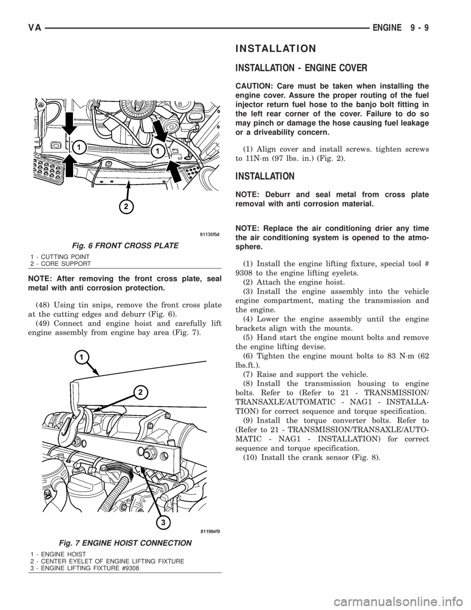
NOTE: After removing the front cross plate, seal
metal with anti corrosion protection.
(48) Using tin snips, remove the front cross plate
at the cutting edges and deburr (Fig. 6).
(49) Connect and engine hoist and carefully lift
engine assembly from engine bay area (Fig. 7).
INSTALLATION
INSTALLATION - ENGINE COVER
CAUTION: Care must be taken when installing the
engine cover. Assure the proper routing of the fuel
injector return fuel hose to the banjo bolt fitting in
the left rear corner of the cover. Failure to do so
may pinch or damage the hose causing fuel leakage
or a driveability concern.
(1) Align cover and install screws. tighten screws
to 11N´m (97 lbs. in.) (Fig. 2).
INSTALLATION
NOTE: Deburr and seal metal from cross plate
removal with anti corrosion material.
NOTE: Replace the air conditioning drier any time
the air conditioning system is opened to the atmo-
sphere.
(1) Install the engine lifting fixture, special tool #
9308 to the engine lifting eyelets.
(2) Attach the engine hoist.
(3) Install the engine assembly into the vehicle
engine compartment, mating the transmission and
the engine.
(4) Lower the engine assembly until the engine
brackets align with the mounts.
(5) Hand start the engine mount bolts and remove
the engine lifting devise.
(6) Tighten the engine mount bolts to 83 N´m (62
lbs.ft.).
(7) Raise and support the vehicle.
(8) Install the transmission housing to engine
bolts. Refer to (Refer to 21 - TRANSMISSION/
TRANSAXLE/AUTOMATIC - NAG1 - INSTALLA-
TION) for correct sequence and torque specification.
(9) Install the torque converter bolts. Refer to
(Refer to 21 - TRANSMISSION/TRANSAXLE/AUTO-
MATIC - NAG1 - INSTALLATION) for correct
sequence and torque specification.
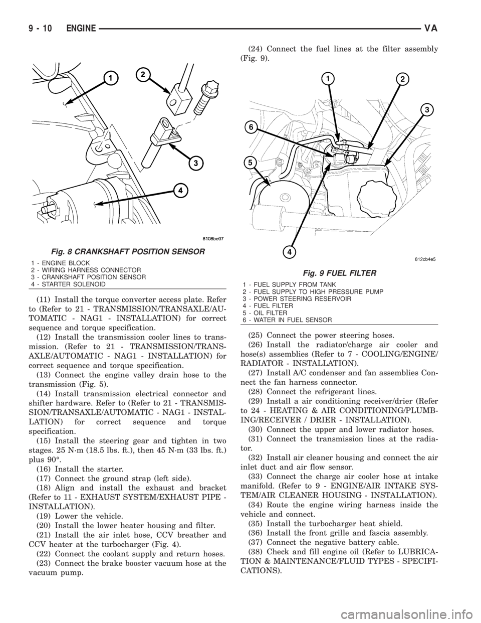
(10) Install the crank sensor (Fig. 8).
Fig. 6 FRONT CROSS PLATE
1 - CUTTING POINT
2 - CORE SUPPORT
Fig. 7 ENGINE HOIST CONNECTION
1 - ENGINE HOIST
2 - CENTER EYELET OF ENGINE LIFTING FIXTURE
3 - ENGINE LIFTING FIXTURE #9308
VAENGINE 9 - 9
Page 1585 of 2305
(11) Install the torque converter access plate. Refer
to (Refer to 21 - TRANSMISSION/TRANSAXLE/AU-
TOMATIC - NAG1 - INSTALLATION) for correct
sequence and torque specification.
(12) Install the transmission cooler lines to trans-
mission. (Refer to 21 - TRANSMISSION/TRANS-
AXLE/AUTOMATIC - NAG1 - INSTALLATION) for
correct sequence and torque specification.
(13) Connect the engine valley drain hose to the
transmission (Fig. 5).
(14) Install transmission electrical connector and
shifter hardware. Refer to (Refer to 21 - TRANSMIS-
SION/TRANSAXLE/AUTOMATIC - NAG1 - INSTAL-
LATION) for correct sequence and torque
specification.
(15) Install the steering gear and tighten in two
stages. 25 N´m (18.5 lbs. ft.), then 45 N´m (33 lbs. ft.)
plus 90É.
(16) Install the starter.
(17) Connect the ground strap (left side).
(18) Align and install the exhaust and bracket
(Refer to 11 - EXHAUST SYSTEM/EXHAUST PIPE -
INSTALLATION).
(19) Lower the vehicle.
(20) Install the lower heater housing and filter.
(21) Install the air inlet hose, CCV breather and
CCV heater at the turbocharger (Fig. 4).
(22) Connect the coolant supply and return hoses.
(23) Connect the brake booster vacuum hose at the
vacuum pump.(24) Connect the fuel lines at the filter assembly
(Fig. 9).
(25) Connect the power steering hoses.
(26) Install the radiator/charge air cooler and
hose(s) assemblies (Refer to 7 - COOLING/ENGINE/
RADIATOR - INSTALLATION).
(27) Install A/C condenser and fan assemblies Con-
nect the fan harness connector.
(28) Connect the refrigerant lines.
(29) Install a air conditioning receiver/drier (Refer
to 24 - HEATING & AIR CONDITIONING/PLUMB-
ING/RECEIVER / DRIER - INSTALLATION).
(30) Connect the upper and lower radiator hoses.
(31) Connect the transmission lines at the radia-
tor.
(32) Install air cleaner housing and connect the air
inlet duct and air flow sensor.
(33) Connect the charge air cooler hose at intake
manifold. (Refer to 9 - ENGINE/AIR INTAKE SYS-
TEM/AIR CLEANER HOUSING - INSTALLATION).
(34) Route the engine wiring harness inside the
vehicle and connect.
(35) Install the turbocharger heat shield.
(36) Install the front grille and fascia assembly.
(37) Connect the negative battery cable.
(38) Check and fill engine oil (Refer to LUBRICA-
TION & MAINTENANCE/FLUID TYPES - SPECIFI-
CATIONS).
Fig. 8 CRANKSHAFT POSITION SENSOR
1 - ENGINE BLOCK
2 - WIRING HARNESS CONNECTOR
3 - CRANKSHAFT POSITION SENSOR
4 - STARTER SOLENOID
Fig. 9 FUEL FILTER
1 - FUEL SUPPLY FROM TANK
2 - FUEL SUPPLY TO HIGH PRESSURE PUMP
3 - POWER STEERING RESERVOIR
4 - FUEL FILTER
5 - OIL FILTER
6 - WATER IN FUEL SENSOR
9 - 10 ENGINEVA
Page 1586 of 2305
(39) Fill cooling system to proper level with the
appropriate coolant.
(40) Evacuate and recharge air conditioning.
(41) Check and refill all ancillary system fluid lev-
els.(42) Start engine and inspect for leaks (Refer to 14
- FUEL SYSTEM - WARNING).
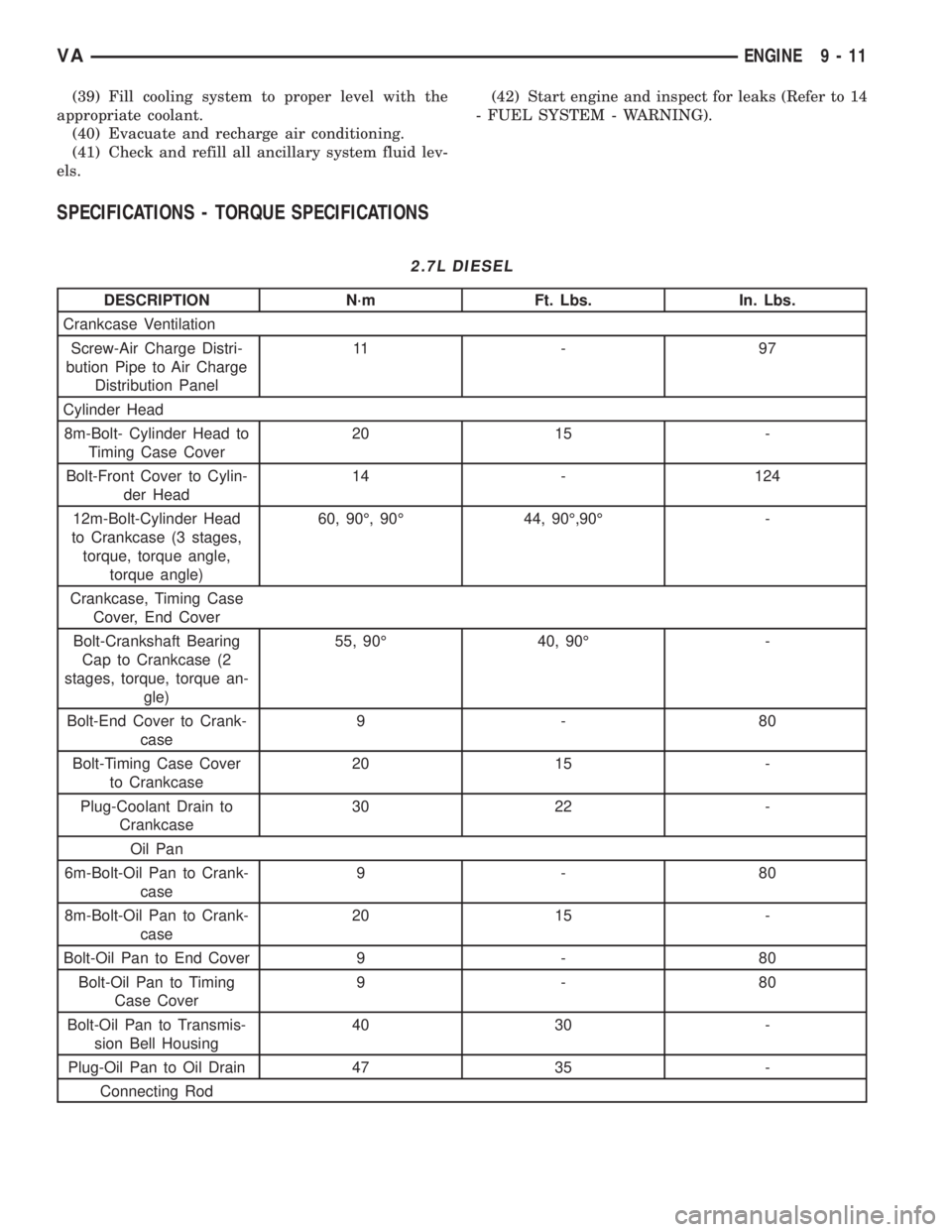
SPECIFICATIONS - TORQUE SPECIFICATIONS
2.7L DIESEL
DESCRIPTION N´m Ft. Lbs. In. Lbs.
Crankcase Ventilation
Screw-Air Charge Distri-
bution Pipe to Air Charge
Distribution Panel11 - 9 7
Cylinder Head
8m-Bolt- Cylinder Head to
Timing Case Cover20 15 -
Bolt-Front Cover to Cylin-
der Head14 - 124
12m-Bolt-Cylinder Head
to Crankcase (3 stages,
torque, torque angle,
torque angle)60, 90É, 90É 44, 90É,90É -
Crankcase, Timing Case
Cover, End Cover
Bolt-Crankshaft Bearing
Cap to Crankcase (2
stages, torque, torque an-
gle)55, 90É 40, 90É -
Bolt-End Cover to Crank-
case9-80
Bolt-Timing Case Cover
to Crankcase20 15 -
Plug-Coolant Drain to
Crankcase30 22 -
Oil Pan
6m-Bolt-Oil Pan to Crank-
case9-80
8m-Bolt-Oil Pan to Crank-
case20 15 -
Bolt-Oil Pan to End Cover 9 - 80
Bolt-Oil Pan to Timing
Case Cover9-80
Bolt-Oil Pan to Transmis-
sion Bell Housing40 30 -
Plug-Oil Pan to Oil Drain 47 35 -
Connecting Rod
VAENGINE 9 - 11