2006 MERCEDES-BENZ SPRINTER Carrier bearing
[x] Cancel search: Carrier bearingPage 757 of 2305
REAR AXLE
TABLE OF CONTENTS
page page
REAR AXLE
DIAGNOSIS AND TESTING................12
STANDARD PROCEDURE - DRAIN AND FILL . . 13
REMOVAL.............................14
INSTALLATION.........................16
SPECIFICATIONS.......................18
SPECIAL TOOLS.......................19
SHAFT-AXLE SINGLE REAR WHEEL
REMOVAL-SINGLE REAR WHEEL..........23
INSTALLATION-SINGLE REAR WHEEL.......24
BEARING/SEAL-AXLE
REMOVAL.............................24
INSTALLATION.........................26
SHAFT-AXLE DUAL REAR WHEELS
REMOVAL-DUAL REAR WHEEL............27
INSTALLATION-DUAL REAR WHEEL........28
BEARING/SEAL-AXLE HUB
REMOVAL.............................28
INSTALLATION.........................29DIFFERENTIAL
REMOVAL.............................31
DISASSEMBLY
DISASSEMBLY-SINGLE REAR WHEEL.....32
DISASSEMBLY-DUAL REAR WHEEL.......33
ASSEMBLY
ASSEMBLY-SINGLE REAR WHEEL........34
ASSEMBLY-DUAL REAR WHEEL..........36
INSTALLATION.........................37
BEARINGS-DIFFERENTIAL CASE
REMOVAL.............................38
INSTALLATION.........................38
SEAL-PINION
REMOVAL.............................39
INSTALLATION.........................40
GEAR-PINION/RING
REMOVAL.............................41
INSTALLATION.........................42
REAR AXLE
DIAGNOSIS AND TESTING
NOTE: Axle seals, axle bearings, pinion seals and
differential cover are the only serviceble compo-
nents. If differential is damaged/noisy the axle must
be replaced.
GEAR NOISE
Axle gear noise can be caused by insufficient lubri-
cant, incorrect backlash, incorrect pinion depth, tooth
contact, worn/damaged gears, or the carrier housing
not having the proper offset and squareness.
Gear noise usually happens at a specific speed
range. The noise can also occur during a specific type
of driving condition. These conditions are accelera-
tion, deceleration, coast, or constant load.
When road testing, first warm-up the axle fluid by
driving the vehicle at least 5 miles and then acceler-
ate the vehicle to the speed range where the noise is
the greatest. Shift out-of-gear and coast through the
peak-noise range. If the noise stops or changes
greatly:
²Check for insufficient lubricant.
²Incorrect ring gear backlash.
²Gear damage.
Differential side gears and pinions can be checked
by turning the vehicle. They usually do not causenoise during straight-ahead driving when the gears
are unloaded. The side gears are loaded during vehi-
cle turns. A worn pinion shaft can also cause a snap-
ping or a knocking noise.
BEARING NOISE
The axle shaft, differential and pinion bearings can
all produce noise when worn or damaged. Bearing
noise can be either a whining, or a growling sound.
Pinion bearingshave a constant-pitch noise. This
noise changes only with vehicle speed. Pinion bearing
noise will be higher pitched because it rotates at a
faster rate. Drive the vehicle and load the differen-
tial. If bearing noise occurs, the rear pinion bearing
is the source of the noise. If the bearing noise is
heard during a coast, the front pinion bearing is the
source.
Differential bearings usually produce a low pitch
noise. Differential bearing noise is similar to pinion
bearing noise. The pitch of differential bearing noise
is also constant and varies only with vehicle speed.
Axle shaft bearingsproduce noise and vibration
when worn or damaged. The noise generally changes
when the bearings are loaded. Road test the vehicle.
Turn the vehicle sharply to the left and to the right.
This will load the bearings and change the noise
level. Where axle bearing damage is slight, the noise
is usually not noticeable at speeds above 30 mph.
3 - 12 REAR AXLEVA
Page 1747 of 2305
²Increased service life and reliability.
²Lower maintenance costs.
TRANSMISSION IDENTIFICATION
The transmission can be generically identified
visually by the presence of a round 13-way connector
located near the front corner of the transmission oil
pan, on the right side. Specific transmission informa-
tion can be found stamped into a pad on the left side
of the transmission, above the oil pan rail.
TRANSMISSION GEAR RATIOS
The gear ratios for the NAG1 automatic transmis-
sion are as follows:
1st Gear............................3.59:1
2nd Gear............................2.19:1
3rd Gear............................1.41:1
4th Gear............................1.00:1
5th Gear............................0.83:1
Reverse.............................3.16:1
TRANSMISSION HOUSING
The converter housing and transmission are made
from a light alloy. These are bolted together and cen-
tered via the outer multi-disc carrier of multi-disc
holding clutch, B1. A coated intermediate plate pro-
vides the sealing. The oil pump and the outer multi-
disc carrier of the multi-disc holding clutch, B1, are
bolted to the converter housing. The stator shaft is
pressed into it and prevented from rotating by
splines. The electrohydraulic unit is bolted to the
transmission housing from underneath. A sheet
metal steel oil pan forms the closure.
MECHANICAL SECTION
The mechanical section consists of a input shaft,
output shaft, a sun gear shaft, and three planetary
gear sets which are coupled to each other. The plan-
etary gear sets each have four planetary pinion
gears. The oil pressure for the torque converter
lock-up clutch and clutch K2 is supplied through
bores in the input shaft. The oil pressure to clutch
K3 is transmitted through the output shaft. The
lubricating oil is distributed through additional bores
in both shafts. All the bearing points of the gear sets,
as well as the freewheeling clutches and actuators,
are supplied with lubricating oil. The parking lock
gear is connected to the output shaft via splines.
Freewheeling clutches F1 and F2 are used to opti-
mize the shifts. The front freewheel, F1, is supported
on the extension of the stator shaft on the transmis-
sion side and, in the locking direction, connects the
sun gear of the front planetary gear set to the trans-
mission housing. In the locking direction, the rear
freewheeling clutch, F2, connects the sun gear of the
center planetary gear set to the sun gear of the rear
planetary gear set.
ELECTROHYDRAULIC CONTROL UNIT
The electrohydraulic control unit comprises the
shift plate made from light alloy for the hydraulic
control and an electrical control unit. The electrical
control unit comprises of a supporting body made of
plastic, into which the electrical components are
assembled. The supporting body is mounted on the
shift plate and screwed to it.
Strip conductors inserted into the supporting body
make the connection between the electrical compo-
nents and a plug connector. The connection to the
wiring harness on the vehicle and the transmission
control module (TCM) is produced via this 13-pin
plug connector with a bayonet lock.
SHIFT GROUPS
The hydraulic control components (including actua-
tors) which are responsible for the pressure distribu-
tion before, during, and after a gear change are
described as a shift group. Each shift group contains
a command valve, a holding pressure shift valve, a
shift pressure shift valve, overlap regulating valve,
and a solenoid.
The hydraulic system contains three shift groups:
1-2/4-5, 2-3, and 3-4. Each shift group can also be
described as being in one of two possible states. The
active shift group is described as being in the shift
phase when it is actively engaging/disengaging a
clutch combination. The 1-2/4-5 shift group control
the B1 and K1 clutches. The 2-3 shift group controls
the K2 and K3 clutches. The 3-4 shift group controls
the K3 and B2 clutches.
OPERATION
The transmission control is divided into the elec-
tronic and hydraulic transmission control functions.
While the electronic transmission control is responsi-
ble for gear selection and for matching the pressures
to the torque to be transmitted, the transmission's
power supply control occurs via hydraulic elements
in the electrohydraulic control module. The oil supply
to the hydraulic elements, such as the hydrodynamic
torque converter, the shift elements and the hydrau-
lic transmission control, is provided by way of an oil
pump connected with the torque converter.
The Transmission Control Module (TCM) allows for
the precise adaptation of pressures to the correspond-
ing operating conditions and to the engine output
during the gearshift phase, resulting in a noticeable
improvement in shift quality. The engine speed limit
can be reached in the individual gears at full throttle
and kickdown. The shift range can be changed in the
forward gears while driving, but the TCM employs a
downshift safeguard to prevent over-revving the
engine. The system offers the additional advantage of
21 - 4 AUTOMATIC TRANSMISSION NAG1 - SERVICE INFORMATIONVA
Page 1796 of 2305
NOTE: During the measurement the snap ring (7)
(Fig. 49) must contact the upper bearing surface of
the groove in the outer multiple-disc carrier (8).
NOTE: Pay attention to sequence of discs. If the
original clutch discs are reused, be sure to return
the disc identified on disassembly as belonging on
top of the spring washer (4) to its original location.
Place new friction multiple-discs in ATF fluid for
one hour before installing.
(4) Insert and measure spring washer (4) (Fig. 49)
and multiple-disc pack B3 (2, 6).
(a) Put multiple-discs for multiple-disc holding
clutch B3 together in the sequence shown in the
illustration and insert individually.
(b)
CAUTION: Apply only light pressure (less than 10 N
(3 lbs.) of force) to the clutch pack when measuring
the clutch clearance with the feeler gauge. Applying
excessive force to the clutch will give an incorrect
reading and lead to a transmission failure.Using a
feeler gauge, determine the play ªLº at three points
between the snap ring (7) and outer multiple-disc
(1). B3 clutch clearance should be 1.0-1.4 mm
(0.039-0.055 in.). Adjust the clearance as necessary.
(c) Adjust with snap-ring (7), if necessary. Snap-
rings are available in thicknesses of 3.2 mm (0.126
in.), 3.5 mm (0.138 in.), 3.8 mm (0.150 in.), 4.1 mm
(0.162 in.), 4.4 mm (0.173 in.), and 4.7 mm (0.185
in.).
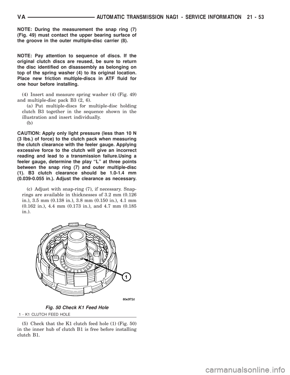
(5) Check that the K1 clutch feed hole (1) (Fig. 50)
in the inner hub of clutch B1 is free before installing
clutch B1.
Fig. 50 Check K1 Feed Hole
1 - K1 CLUTCH FEED HOLE
VAAUTOMATIC TRANSMISSION NAG1 - SERVICE INFORMATION 21 - 53
Page 1830 of 2305
TORQUE SPECIFICATIONS
DESCRIPTION N´m Ft. Lbs. In. Lbs.
Bolt, Transmission Hous-
ing to Engine38 28 -
Bolt, Transmission Oil
Line to Transmission
Housing34 25 -
Bolt, Oil Fill Tube to
Transmisson Housing8-71
Bolt, Oil Fill Tube to Cyl-
inder Head8-71
Bolt, Torque Converter to
Drive Plate50 37 -
Bolt, B2 Clutch Carrier 16 - 141
Bolt, B1 Carrier to Con-
verter Housing10 - 88.5
Nut, Propeller Flange 200 147.5 -
Bolt, Electrohydraulic Unit 8 - 71
Bolt, Transmission Hous-
ing to Converter Housing20 - 177
Bolts, Oil Pan 8 - 71
Screws, Valve Body/Hous-
ing Side Cover4-35
Bolt, Shift Plate 8 - 71
Bolt, Solenoid Leaf Spring 8 - 71
Plug, Oil Pan Drain 20 - 177
Nut, Shifter Mechanism to
Floor Pan7-65
SPECIAL TOOLS - AUTOMATIC TRANSMIS-
SION - NAG1
SPECIAL TOOL CROSS REFERENCE CHART
MB
TOOL #MILLER
TOOL #DESCRIPTION
N/A C-3339 DIAL INDICATOR SET
N/A C-4171 DRIVE HANDLE
N/A 6311 GAUGE BAR
N/A 8266 END-PLAY SET
N/A 8266-18 END-PLAY ADAPTER
N/A 8863B DIPSTICK
140 586
13 43 008900 MULTI-USE SPRING
COMPRESSOR
208 589
00 21 008901 PRESSING TOOL
N/A 8902A SEAL INSTALLER
N/A 9078 STAKING TOOL
MB
TOOL #MILLER
TOOL #DESCRIPTION
N/A 9082 BEARING REMOVER
N/A 9287 BEARING INSTALLER
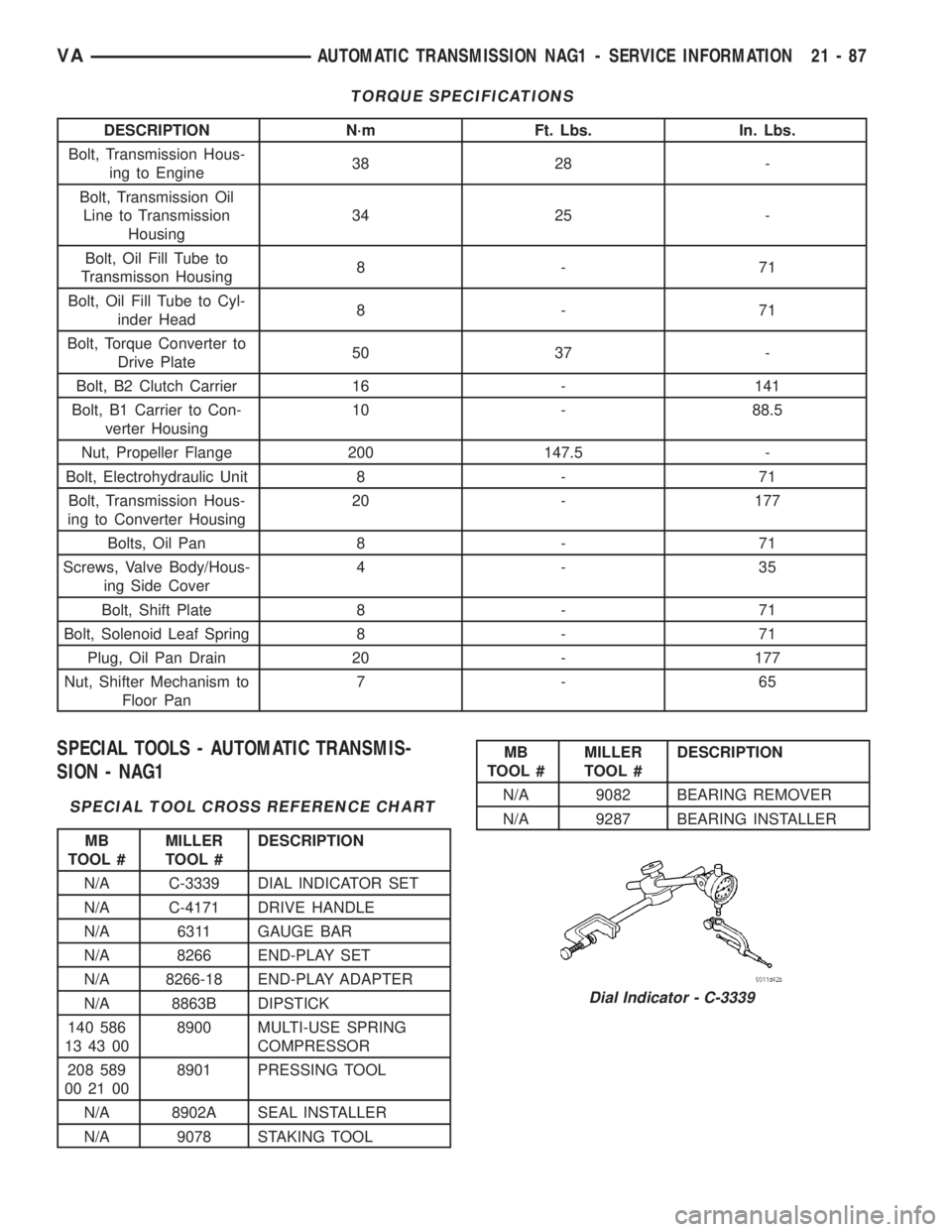
Dial Indicator - C-3339
VAAUTOMATIC TRANSMISSION NAG1 - SERVICE INFORMATION 21 - 87
Page 1838 of 2305
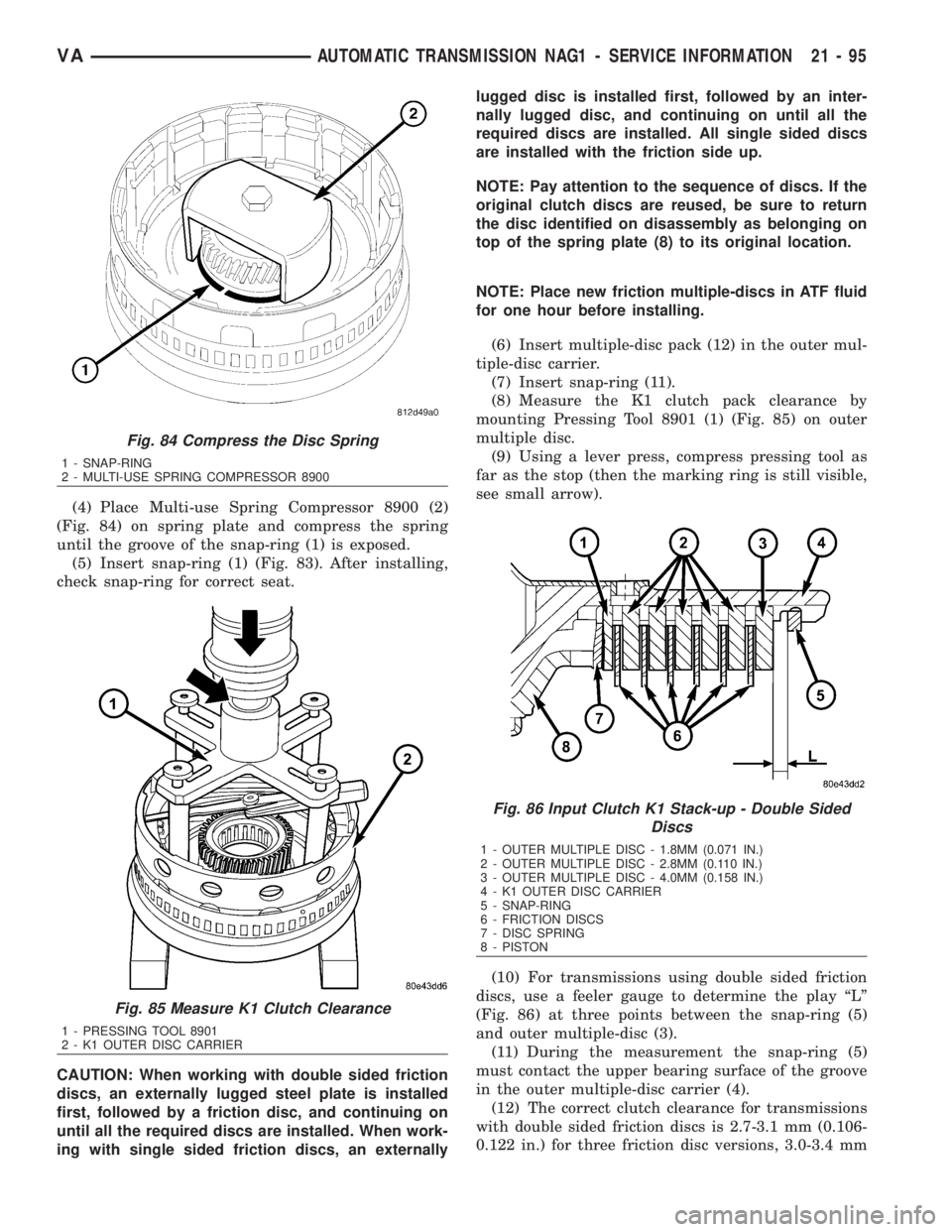
(4) Place Multi-use Spring Compressor 8900 (2)
(Fig. 84) on spring plate and compress the spring
until the groove of the snap-ring (1) is exposed.
(5) Insert snap-ring (1) (Fig. 83). After installing,
check snap-ring for correct seat.
CAUTION: When working with double sided friction
discs, an externally lugged steel plate is installed
first, followed by a friction disc, and continuing on
until all the required discs are installed. When work-
ing with single sided friction discs, an externallylugged disc is installed first, followed by an inter-
nally lugged disc, and continuing on until all the
required discs are installed. All single sided discs
are installed with the friction side up.
NOTE: Pay attention to the sequence of discs. If the
original clutch discs are reused, be sure to return
the disc identified on disassembly as belonging on
top of the spring plate (8) to its original location.
NOTE: Place new friction multiple-discs in ATF fluid
for one hour before installing.
(6) Insert multiple-disc pack (12) in the outer mul-
tiple-disc carrier.
(7) Insert snap-ring (11).
(8) Measure the K1 clutch pack clearance by
mounting Pressing Tool 8901 (1) (Fig. 85) on outer
multiple disc.
(9) Using a lever press, compress pressing tool as
far as the stop (then the marking ring is still visible,
see small arrow).
(10) For transmissions using double sided friction
discs, use a feeler gauge to determine the play ªLº
(Fig. 86) at three points between the snap-ring (5)
and outer multiple-disc (3).
(11) During the measurement the snap-ring (5)
must contact the upper bearing surface of the groove
in the outer multiple-disc carrier (4).
(12) The correct clutch clearance for transmissions
with double sided friction discs is 2.7-3.1 mm (0.106-
0.122 in.) for three friction disc versions, 3.0-3.4 mm
Fig. 84 Compress the Disc Spring
1 - SNAP-RING
2 - MULTI-USE SPRING COMPRESSOR 8900
Fig. 85 Measure K1 Clutch Clearance
1 - PRESSING TOOL 8901
2 - K1 OUTER DISC CARRIER
Fig. 86 Input Clutch K1 Stack-up - Double Sided
Discs
1 - OUTER MULTIPLE DISC - 1.8MM (0.071 IN.)
2 - OUTER MULTIPLE DISC - 2.8MM (0.110 IN.)
3 - OUTER MULTIPLE DISC - 4.0MM (0.158 IN.)
4 - K1 OUTER DISC CARRIER
5 - SNAP-RING
6 - FRICTION DISCS
7 - DISC SPRING
8 - PISTON
VAAUTOMATIC TRANSMISSION NAG1 - SERVICE INFORMATION 21 - 95
Page 1839 of 2305
(0.118-0.134 in.) for four disc versions, 3.3-3.7 mm
(0.130-0.146 in.) for five disc versions, and 3.6-4.0
mm (0.142-0.158 in.) for six disc versions.
(13) Adjust with snap-ring (5), if necessary. Snap-
rings are available in thicknesses of 2.6 mm (0.102
in.), 2.9 mm (0.114 in.), 3.2 mm (0.126 in.), 3.5 mm
(0.138 in.), 3.8 mm (0.150 in.), and 4.1 mm (0.162
in.).
(14) Insert front freewheeling clutch F1 (2) and fit
snap-ring (3). The freewheeling clutch F1 (2) must be
installed in the direction of the arrow.
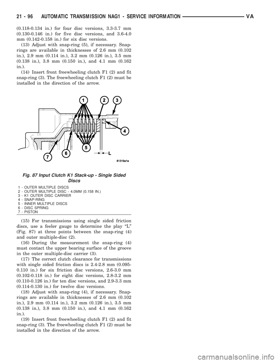
(15) For transmissions using single sided friction
discs, use a feeler gauge to determine the play ªLº
(Fig. 87) at three points between the snap-ring (4)
and outer multiple-disc (2).
(16) During the measurement the snap-ring (4)
must contact the upper bearing surface of the groove
in the outer multiple-disc carrier (3).
(17) The correct clutch clearance for transmissions
with single sided friction discs is 2.4-2.8 mm (0.095-
0.110 in.) for six friction disc versions, 2.6-3.0 mm
(0.102-0.118 in.) for eight disc versions, 2.8-3.2 mm
(0.110-0.126 in.) for ten disc versions, and 2.9-3.3 mm
(0.114-0.130 in.) for twelve disc versions.
(18) Adjust with snap-ring (4), if necessary. Snap-
rings are available in thicknesses of 2.6 mm (0.102
in.), 2.9 mm (0.114 in.), 3.2 mm (0.126 in.), 3.5 mm
(0.138 in.), 3.8 mm (0.150 in.), and 4.1 mm (0.162
in.).
(19) Insert front freewheeling clutch F1 (2) and fit
snap-ring (3). The freewheeling clutch F1 (2) must be
installed in the direction of the arrow.
Fig. 87 Input Clutch K1 Stack-up - Single Sided
Discs
1 - OUTER MULTIPLE DISCS
2 - OUTER MULTIPLE DISC - 4.0MM (0.158 IN.)
3 - K1 OUTER DISC CARRIER
4 - SNAP-RING
5 - INNER MULTIPLE DISCS
6 - DISC SPRING
7 - PISTON
21 - 96 AUTOMATIC TRANSMISSION NAG1 - SERVICE INFORMATIONVA
Page 1840 of 2305
INPUT CLUTCH K2
DISASSEMBLY
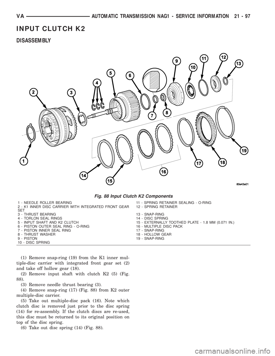
(1) Remove snap-ring (19) from the K1 inner mul-
tiple-disc carrier with integrated front gear set (2)
and take off hollow gear (18).
(2) Remove input shaft with clutch K2 (5) (Fig.
88).
(3) Remove needle thrust bearing (3).
(4) Remove snap-ring (17) (Fig. 88) from K2 outer
multiple-disc carrier.
(5) Take out multiple-disc pack (16). Note which
clutch disc is removed just prior to the disc spring
(14) for re-assembly. If the clutch discs are re-used,
this disc must be returned to its original position on
top of the disc spring.
(6) Take out disc spring (14) (Fig. 88).
Fig. 88 Input Clutch K2 Components
1 - NEEDLE ROLLER BEARING 11 - SPRING RETAINER SEALING - O-RING
2 - K1 INNER DISC CARRIER WITH INTEGRATED FRONT GEAR
SET12 - SPRING RETAINER
3 - THRUST BEARING 13 - SNAP-RING
4 - TORLON SEAL RINGS 14 - DISC SPRING
5 - INPUT SHAFT AND K2 CLUTCH 15 - EXTERNALLY TOOTHED PLATE - 1.8 MM (0.071 IN.)
6 - PISTON OUTER SEAL RING - O-RING 16 - MULTIPLE DISC PACK
7 - PISTON INNER SEAL RING 17 - SNAP-RING
8 - THRUST WASHER 18 - HOLLOW GEAR
9 - PISTON 19 - SNAP-RING
10 - DISC SPRING
VAAUTOMATIC TRANSMISSION NAG1 - SERVICE INFORMATION 21 - 97
Page 1842 of 2305
ASSEMBLY
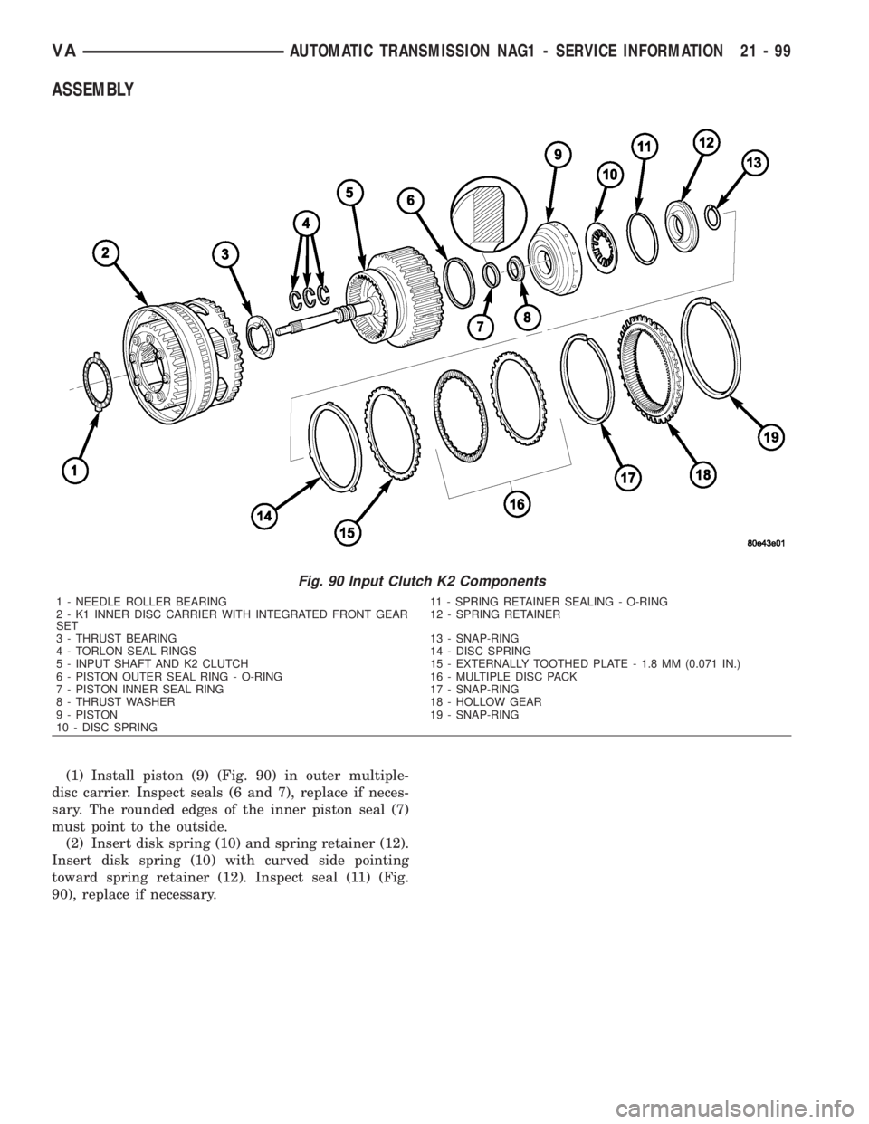
(1) Install piston (9) (Fig. 90) in outer multiple-
disc carrier. Inspect seals (6 and 7), replace if neces-
sary. The rounded edges of the inner piston seal (7)
must point to the outside.
(2) Insert disk spring (10) and spring retainer (12).
Insert disk spring (10) with curved side pointing
toward spring retainer (12). Inspect seal (11) (Fig.
90), replace if necessary.
Fig. 90 Input Clutch K2 Components
1 - NEEDLE ROLLER BEARING 11 - SPRING RETAINER SEALING - O-RING
2 - K1 INNER DISC CARRIER WITH INTEGRATED FRONT GEAR
SET12 - SPRING RETAINER
3 - THRUST BEARING 13 - SNAP-RING
4 - TORLON SEAL RINGS 14 - DISC SPRING
5 - INPUT SHAFT AND K2 CLUTCH 15 - EXTERNALLY TOOTHED PLATE - 1.8 MM (0.071 IN.)
6 - PISTON OUTER SEAL RING - O-RING 16 - MULTIPLE DISC PACK
7 - PISTON INNER SEAL RING 17 - SNAP-RING
8 - THRUST WASHER 18 - HOLLOW GEAR
9 - PISTON 19 - SNAP-RING
10 - DISC SPRING
VAAUTOMATIC TRANSMISSION NAG1 - SERVICE INFORMATION 21 - 99