2006 MERCEDES-BENZ SPRINTER diagram
[x] Cancel search: diagramPage 1087 of 2305
²Grounds and ground connectors are identified
with a ªGº and follow the same series numbering as
the in-line connectors.
²Splices are identified with an ªSº and follow the
same series numbering as the in-line connectors.
²Component connectors are identified by the com-
ponent name instead of a number. Multiple connec-
tors on a component use a C1, C2, etc. identifier.
LOCATIONS
Section 8W-91 contains connector/ground/splice
location illustrations. The illustrations contain the
connector name (or number)/ground number/splice
number and component identification. Connector/
ground/splice location charts in section 8W-91 refer-
ence the figure numbers of the illustrations.
The abbreviation T/O is used in the component
location section to indicate a point in which the wir-
ing harness branches out to a component. The abbre-
viation N/S means Not Shown in the illustrations
WARNINGS - GENERAL
WARNINGSprovide information to prevent per-
sonal injury and vehicle damage. Below is a list of
general warnings that should be followed any time a
vehicle is being serviced.
WARNING: ALWAYS WEAR SAFETY GLASSES FOR
EYE PROTECTION.
WARNING: USE SAFETY STANDS ANYTIME A PRO-
CEDURE REQUIRES BEING UNDER A VEHICLE.
WARNING: BE SURE THAT THE IGNITION SWITCH
ALWAYS IS IN THE OFF POSITION, UNLESS THE
PROCEDURE REQUIRES IT TO BE ON.
WARNING: SET THE PARKING BRAKE WHEN
WORKING ON ANY VEHICLE. AN AUTOMATIC
TRANSMISSION SHOULD BE IN PARK. A MANUAL
TRANSMISSION SHOULD BE IN NEUTRAL.
WARNING: OPERATE THE ENGINE ONLY IN A
WELL-VENTILATED AREA.
WARNING: KEEP AWAY FROM MOVING PARTS
WHEN THE ENGINE IS RUNNING, ESPECIALLY THE
FAN AND BELTS.
WARNING: TO PREVENT SERIOUS BURNS, AVOID
CONTACT WITH HOT PARTS SUCH AS THE RADIA-TOR, EXHAUST MANIFOLD(S), TAIL PIPE, CATA-
LYTIC CONVERTER AND MUFFLER.
WARNING: DO NOT ALLOW FLAME OR SPARKS
NEAR THE BATTERY. GASES ARE ALWAYS
PRESENT IN AND AROUND THE BATTERY.
WARNING: ALWAYS REMOVE RINGS, WATCHES,
LOOSE HANGING JEWELRY AND AVOID LOOSE
CLOTHING.
DIAGNOSIS AND TESTING
WIRING HARNESS
TROUBLESHOOTING TOOLS
When diagnosing a problem in an electrical circuit
there are several common tools necessary. These tools
are listed and explained below.
²Jumper Wire - This is a test wire used to con-
nect two points of a circuit. It can be used to bypass
an open in a circuit.
WARNING: NEVER USE A JUMPER WIRE ACROSS
A LOAD, SUCH AS A MOTOR, CONNECTED
BETWEEN A BATTERY FEED AND GROUND.
²Voltmeter - Used to check for voltage on a cir-
cuit. Always connect the black lead to a known good
ground and the red lead to the positive side of the
circuit.
CAUTION: Most of the electrical components used
in today's vehicles are Solid State. When checking
voltages in these circuits, use a meter with a 10 -
megohm or greater impedance rating.
²Ohmmeter - Used to check the resistance
between two points of a circuit. Low or no resistance
in a circuit means good continuity.
CAUTION: Most of the electrical components used
in today's vehicles are Solid State. When checking
resistance in these circuits use a meter with a 10 -
megohm or greater impedance rating. In addition,
make sure the power is disconnected from the cir-
cuit. Circuits that are powered up by the vehicle's
electrical system can cause damage to the equip-
ment and provide false readings.
²Probing Tools - These tools are used for probing
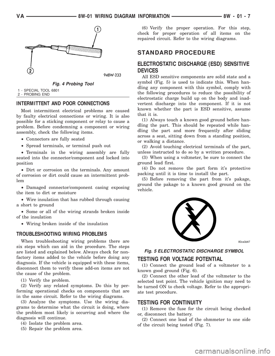
terminals in connectors (Fig. 4). Select the proper
size tool from Special Tool Package 6807, and insert
it into the terminal being tested. Use the other end
of the tool to insert the meter probe.
8W - 01 - 6 8W-01 WIRING DIAGRAM INFORMATIONVA
Page 1088 of 2305
INTERMITTENT AND POOR CONNECTIONS
Most intermittent electrical problems are caused
by faulty electrical connections or wiring. It is also
possible for a sticking component or relay to cause a
problem. Before condemning a component or wiring
assembly, check the following items.
²Connectors are fully seated
²Spread terminals, or terminal push out
²Terminals in the wiring assembly are fully
seated into the connector/component and locked into
position
²Dirt or corrosion on the terminals. Any amount
of corrosion or dirt could cause an intermittent prob-
lem
²Damaged connector/component casing exposing
the item to dirt or moisture
²Wire insulation that has rubbed through causing
a short to ground
²Some or all of the wiring strands broken inside
of the insulation
²Wiring broken inside of the insulation
TROUBLESHOOTING WIRING PROBLEMS
When troubleshooting wiring problems there are
six steps which can aid in the procedure. The steps
are listed and explained below. Always check for non-
factory items added to the vehicle before doing any
diagnosis. If the vehicle is equipped with these items,
disconnect them to verify these add-on items are not
the cause of the problem.
(1) Verify the problem.
(2) Verify any related symptoms. Do this by per-
forming operational checks on components that are
in the same circuit. Refer to the wiring diagrams.
(3) Analyze the symptoms. Use the wiring dia-
grams to determine what the circuit is doing, where
the problem most likely is occurring and where the
diagnosis will continue.
(4) Isolate the problem area.
(5) Repair the problem area.(6) Verify the proper operation. For this step,
check for proper operation of all items on the
repaired circuit. Refer to the wiring diagrams.
STANDARD PROCEDURE
ELECTROSTATIC DISCHARGE (ESD) SENSITIVE
DEVICES
All ESD sensitive components are solid state and a
symbol (Fig. 5) is used to indicate this. When han-
dling any component with this symbol, comply with
the following procedures to reduce the possibility of
electrostatic charge build up on the body and inad-
vertent discharge into the component. If it is not
known whether the part is ESD sensitive, assume
that it is.
(1) Always touch a known good ground before han-
dling the part. This should be repeated while han-
dling the part and more frequently after sliding
across a seat, sitting down from a standing position,
or walking a distance.
(2) Avoid touching electrical terminals of the part,
unless instructed to do so by a written procedure.
(3) When using a voltmeter, be sure to connect the
ground lead first.
(4) Do not remove the part form it's protective
packing until it is time to install the part.
(5) Before removing the part from it's pakage,
ground the pakage to a known good ground on the
vehicle.
TESTING FOR VOLTAGE POTENTIAL
(1) Connect the ground lead of a voltmeter to a
known good ground (Fig. 6).
(2) Connect the other lead of the voltmeter to the
selected test point. The vehicle ignition may need to
be turned ON to check voltage. Refer to the appropri-
ate test procedure.
TESTING FOR CONTINUITY
(1) Remove the fuse for the circuit being checked
or, disconnect the battery.
(2) Connect one lead of the ohmmeter to one side
of the circuit being tested (Fig. 7).
Fig. 4 Probing Tool
1 - SPECIAL TOOL 6801
2 - PROBING END
Fig. 5 ELECTROSTATIC DISCHARGE SYMBOL
VA8W-01 WIRING DIAGRAM INFORMATION 8W - 01 - 7
Page 1089 of 2305
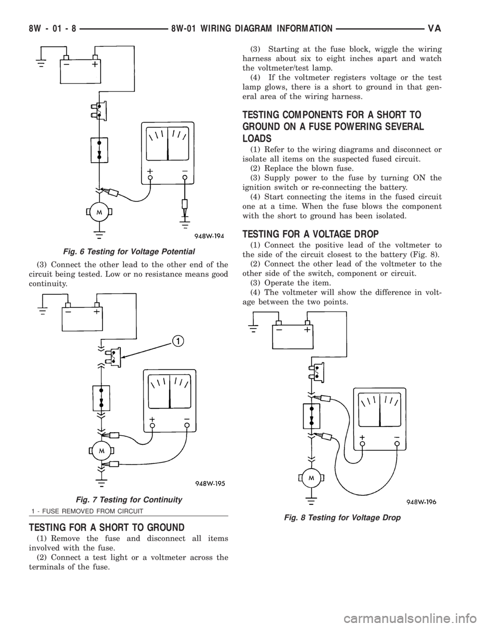
(3) Connect the other lead to the other end of the
circuit being tested. Low or no resistance means good
continuity.
TESTING FOR A SHORT TO GROUND
(1) Remove the fuse and disconnect all items
involved with the fuse.
(2) Connect a test light or a voltmeter across the
terminals of the fuse.(3) Starting at the fuse block, wiggle the wiring
harness about six to eight inches apart and watch
the voltmeter/test lamp.
(4) If the voltmeter registers voltage or the test
lamp glows, there is a short to ground in that gen-
eral area of the wiring harness.
TESTING COMPONENTS FOR A SHORT TO
GROUND ON A FUSE POWERING SEVERAL
LOADS
(1) Refer to the wiring diagrams and disconnect or
isolate all items on the suspected fused circuit.
(2) Replace the blown fuse.
(3) Supply power to the fuse by turning ON the
ignition switch or re-connecting the battery.
(4) Start connecting the items in the fused circuit
one at a time. When the fuse blows the component
with the short to ground has been isolated.
TESTING FOR A VOLTAGE DROP
(1) Connect the positive lead of the voltmeter to
the side of the circuit closest to the battery (Fig. 8).
(2) Connect the other lead of the voltmeter to the
other side of the switch, component or circuit.
(3) Operate the item.
(4) The voltmeter will show the difference in volt-
age between the two points.Fig. 6 Testing for Voltage Potential
Fig. 7 Testing for Continuity
1 - FUSE REMOVED FROM CIRCUITFig. 8 Testing for Voltage Drop
8W - 01 - 8 8W-01 WIRING DIAGRAM INFORMATIONVA
Page 1090 of 2305
CONNECTOR
REMOVAL
(1) Disconnect battery.
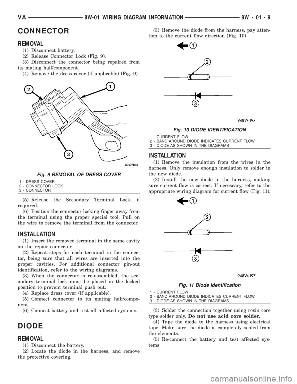
(2) Release Connector Lock (Fig. 9).
(3) Disconnect the connector being repaired from
its mating half/component.
(4) Remove the dress cover (if applicable) (Fig. 9).
(5) Release the Secondary Terminal Lock, if
required.
(6) Position the connector locking finger away from
the terminal using the proper special tool. Pull on
the wire to remove the terminal from the connector.
INSTALLATION
(1) Insert the removed terminal in the same cavity
on the repair connector.
(2) Repeat steps for each terminal in the connec-
tor, being sure that all wires are inserted into the
proper cavities. For additional connector pin-out
identification, refer to the wiring diagrams.
(3) When the connector is re-assembled, the sec-
ondary terminal lock must be placed in the locked
position to prevent terminal push out.
(4) Replace dress cover (if applicable).
(5) Connect connector to its mating half/compo-
nent.
(6) Connect battery and test all affected systems.
DIODE
REMOVAL
(1) Disconnect the battery.
(2) Locate the diode in the harness, and remove
the protective covering.(3) Remove the diode from the harness, pay atten-
tion to the current flow direction (Fig. 10).
INSTALLATION
(1) Remove the insulation from the wires in the
harness. Only remove enough insulation to solder in
the new diode.
(2) Install the new diode in the harness, making
sure current flow is correct. If necessary, refer to the
appropriate wiring diagram for current flow (Fig. 11).
(3) Solder the connection together using rosin core
type solder only.Do not use acid core solder.
(4) Tape the diode to the harness using electrical
tape. Make sure the diode is completely sealed from
the elements.
(5) Re-connect the battery and test affected sys-
tems.
Fig. 9 REMOVAL OF DRESS COVER
1 - DRESS COVER
2 - CONNECTOR LOCK
3 - CONNECTOR
Fig. 10 DIODE IDENTIFICATION
1 - CURRENT FLOW
2 - BAND AROUND DIODE INDICATES CURRENT FLOW
3 - DIODE AS SHOWN IN THE DIAGRAMS
Fig. 11 Diode Identification
1 - CURRENT FLOW
2 - BAND AROUND DIODE INDICATES CURRENT FLOW
3 - DIODE AS SHOWN IN THE DIAGRAMS
VA8W-01 WIRING DIAGRAM INFORMATION 8W - 01 - 9
Page 1091 of 2305
TERMINAL
REMOVAL
(1) Follow steps for removing terminals described
in the connector removal section.
(2) Cut the wire 6 inches from the back of the con-
nector.
INSTALLATION
(1) Select a wire from the terminal repair kit that
best matches the color and gage of the wire being
repaired.
(2) Cut the repair wire to the proper length and
remove one±half (1/2) inch of insulation.
(3) Splice the repair wire to the wire harness (see
wire splicing procedure) .
(4) Insert the repaired wire into the connector.
(5) Install the connector locking wedge, if required,
and reconnect the connector to its mating half/compo-
nent.
(6) Re-tape the wire harness starting at 1±1/2
inches behind the connector and 2 inches past the
repair.
(7) Connect battery and test all affected systems.
WIRE
STANDARD PROCEDURE
WIRE SPLICING
When splicing a wire, it is important that the cor-
rect gage be used as shown in the wiring diagrams.
(1) Remove one-half (1/2) inch of insulation from
each wire that needs to be spliced.
(2) Place a piece of adhesive lined heat shrink tub-
ing on one side of the wire. Make sure the tubing will
be long enough to cover and seal the entire repair
area.
(3) Place the strands of wire overlapping each
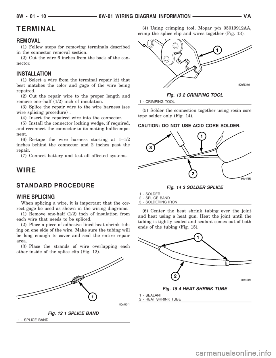
other inside of the splice clip (Fig. 12).(4) Using crimping tool, Mopar p/n 05019912AA,
crimp the splice clip and wires together (Fig. 13).
(5) Solder the connection together using rosin core
type solder only (Fig. 14).
CAUTION: DO NOT USE ACID CORE SOLDER.
(6) Center the heat shrink tubing over the joint
and heat using a heat gun. Heat the joint until the
tubing is tightly sealed and sealant comes out of both
ends of the tubing (Fig. 15).
Fig. 12 1 SPLICE BAND
1 - SPLICE BAND
Fig. 13 2 CRIMPING TOOL
1 - CRIMPING TOOL
Fig. 14 3 SOLDER SPLICE
1 - SOLDER
2 - SPLICE BAND
3 - SOLDERING IRON
Fig. 15 4 HEAT SHRINK TUBE
1 - SEALANT
2 - HEAT SHRINK TUBE
8W - 01 - 10 8W-01 WIRING DIAGRAM INFORMATIONVA
Page 1504 of 2305
8W-91 CONNECTOR/GROUND/SPLICE LOCATION
TABLE OF CONTENTS
page
CONNECTOR/GROUND/SPLICE LOCATION
DESCRIPTION..........................1
CONNECTOR/GROUND/SPLICE
LOCATION
DESCRIPTION
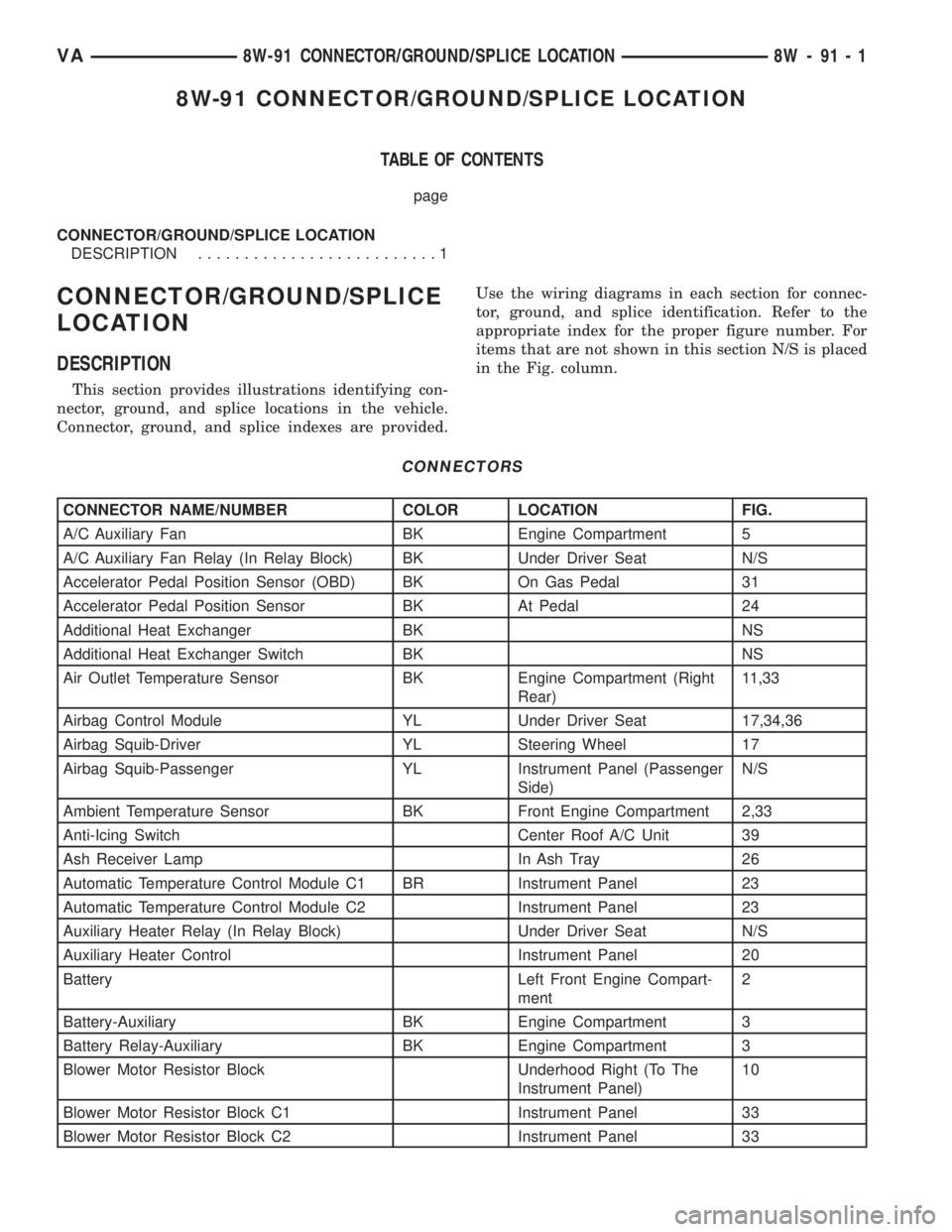
This section provides illustrations identifying con-
nector, ground, and splice locations in the vehicle.
Connector, ground, and splice indexes are provided.Use the wiring diagrams in each section for connec-
tor, ground, and splice identification. Refer to the
appropriate index for the proper figure number. For
items that are not shown in this section N/S is placed
in the Fig. column.
CONNECTORS
CONNECTOR NAME/NUMBER COLOR LOCATION FIG.
A/C Auxiliary Fan BK Engine Compartment 5
A/C Auxiliary Fan Relay (In Relay Block) BK Under Driver Seat N/S
Accelerator Pedal Position Sensor (OBD) BK On Gas Pedal 31
Accelerator Pedal Position Sensor BK At Pedal 24
Additional Heat Exchanger BK NS
Additional Heat Exchanger Switch BK NS
Air Outlet Temperature Sensor BK Engine Compartment (Right
Rear)11,33
Airbag Control Module YL Under Driver Seat 17,34,36
Airbag Squib-Driver YL Steering Wheel 17
Airbag Squib-Passenger YL Instrument Panel (Passenger
Side)N/S
Ambient Temperature Sensor BK Front Engine Compartment 2,33
Anti-Icing Switch Center Roof A/C Unit 39
Ash Receiver Lamp In Ash Tray 26
Automatic Temperature Control Module C1 BR Instrument Panel 23
Automatic Temperature Control Module C2 Instrument Panel 23
Auxiliary Heater Relay (In Relay Block) Under Driver Seat N/S
Auxiliary Heater Control Instrument Panel 20
Battery Left Front Engine Compart-
ment2
Battery-Auxiliary BK Engine Compartment 3
Battery Relay-Auxiliary BK Engine Compartment 3
Blower Motor Resistor Block Underhood Right (To The
Instrument Panel)10
Blower Motor Resistor Block C1 Instrument Panel 33
Blower Motor Resistor Block C2 Instrument Panel 33
VA8W-91 CONNECTOR/GROUND/SPLICE LOCATION 8W - 91 - 1
Page 1570 of 2305
8W-97 POWER DISTRIBUTION
TABLE OF CONTENTS
page page
POWER DISTRIBUTION
DESCRIPTION..........................1
OPERATION............................1
CIGAR LIGHTER OUTLET
DESCRIPTION..........................1
OPERATION............................2
DIAGNOSIS AND TESTING - CIGAR LIGHTER
OUTLET.............................2
REMOVAL.............................2
CIRCUIT BREAKER
DESCRIPTION..........................2
OPERATION............................2
DIAGNOSIS AND TESTING - CIRCUIT
BREAKER............................2
FUSE BLOCK #1
DESCRIPTION..........................2
OPERATION............................3
REMOVAL.............................3
INSTALLATION..........................3FUSE BLOCK #2
DESCRIPTION..........................3
OPERATION............................3
POWER DISTRIBUTION CENTER
DESCRIPTION..........................3
OPERATION............................3
POWER OUTLET
DESCRIPTION..........................3
OPERATION............................4
DIAGNOSIS AND TESTING - POWER OUTLET . 4
REMOVAL.............................4
INSTALLATION..........................4
RELAY
DESCRIPTION..........................4
OPERATION............................5
DIAGNOSIS AND TESTING - RELAY.........5
REMOVAL.............................5
INSTALLATION..........................5
POWER DISTRIBUTION
DESCRIPTION
This section describes the power distribution com-
ponents used on this model as well as the methods in
which battery voltage and charging system voltage is
distributed throughout the vehicle. The power distri-
bution system for this vehicle consists of the follow-
ing major components which are covered in further
detail later in this section:
²Fuseblock #1
²Fuseblock #2
²Power Distribution Center (PDC)
The power distribution system also incorporates
various types of circuit control and protection fea-
tures, including:
²Automatic resetting circuit breakers
²Blade-type fuses
²Cartridge fuses
²Relays
Following are general descriptions and theory of
operation for the major components in the power dis-
tribution system. Refer to Wiring for the location of
complete circuit diagrams for the various power dis-
tribution system components.
OPERATION
The power distribution system for this vehicle is
designed to provide safe, reliable, and centralized dis-
tribution points for the electrical current required to
operate all of the standard and optional factory-in-
stalled electrical and powertrain, chassis, safety,
security and convenience systems. At the same time,
the power distribution system was designed to pro-
vide easy access to these electrical distribution points
for the vehicle technician to use when conducting
diagnosis and repair of faulty circuits. The power dis-
tribution system can also prove useful for the addi-
tion of electrical circuits that may be required to
operate accessories that the vehicle owner may
choose to have installed in the aftermarket.
CIGAR LIGHTER OUTLET
DESCRIPTION
The cigar lighter outlet is installed in the instru-
ment panel, near the center of the instrument panel.
The cigar lighter outlet is secured by a snap fit
within the instrument panel.
The cigar lighter knob/heating element, and the
cigar lighter outlet are available for service. These
components cannot be repaired and, if faulty or dam-
aged, they must be replaced.
VA8W-97 POWER DISTRIBUTION 8W - 97 - 1
Page 1571 of 2305
OPERATION
The cigar lighter consists of two major components:
a knob and heating element unit, and the cigar
lighter base or receptacle shell. The receptacle shell
is connected to ground, and an insulated contact in
the bottom of the shell is connected to battery cur-
rent. The cigar lighter receives battery voltage from a
fuse in the fuseblock only when the ignition switch is
in the Accessory or On positions.
The knob and heating element are encased within
a spring-loaded housing, which also features a sliding
protective heat shield. When the heating element is
inserted in the receptacle shell, the heating element
resistor coil is grounded through its housing to the
receptacle shell. If the cigar lighter knob is pushed
inward, the heat shield slides up toward the knob
exposing the heating element.
Two small spring-clip retainers are located on
either side of the insulated contact inside the bottom
of the receptacle shell. These clips engage and hold
the heating element against the insulated contact
long enough for the resistor coil to heat up and glow.
When the resistor coil becomes sufficiently heated,
excess heat radiates from the heating element caus-
ing the spring-clips to expand. Once the spring-clips
expand far enough to release the heating element,
the spring-loaded housing forces the knob and heat-
ing element to pop back outward to their relaxed
position. When the cigar lighter knob and element
are pulled out of the receptacle shell, the protective
heat shield slides downward on the housing so that
the heating element is recessed and shielded around
its circumference for safety.
DIAGNOSIS AND TESTING - CIGAR LIGHTER
OUTLET
For cigar lighter outlet diagnosis and testing pro-
cedures (Refer to 8 - ELECTRICAL/POWER DISTRI-
BUTION/POWER OUTLET - DIAGNOSIS AND
TESTING)
REMOVAL
For cigar lighter outlet removal procedure (Refer to
8 - ELECTRICAL/POWER DISTRIBUTION/POWER
OUTLET - REMOVAL).
CIRCUIT BREAKER
DESCRIPTION
Automatic resetting circuit breakers are used to
protect the power window voltage supply circuits.
These circuit breakers can protect the systems from a
short circuit, or from an overload condition caused byan obstructed or stuck power window regulator or
switch.
The circuit breaker cannot be repaired and, if
faulty or damaged, it must be replaced.
OPERATION
The circuit breaker contains a bi-metal strip sand-
wiched between two contacts forming the connection
in the circuit. An overload condition causes the
bi-metal strip to heat and bend to the open position,
disconnecting current flow to the circuit. Then as the
system overload or short circuit is removed, the
bi-metal strip cools, re-establishing contact to allow
current flow to the circuit.
DIAGNOSIS AND TESTING - CIRCUIT BREAKER
For complete circuit descriptions and diagrams,
refer toWiring.
(1) Locate the correct circuit breaker in the fuse-
block. Pull out the circuit breaker slightly, but be cer-
tain that the circuit breaker terminals still contact
the terminals in the fuseblock cavities.
(2) Connect the negative lead of a 12-volt DC volt-
meter to a good ground.
(3) With the voltmeter positive lead, check both
terminals of the circuit breaker for battery voltage.
If only one terminal has battery voltage, the circuit
breaker is faulty and must be replaced. If neither ter-
minal has battery voltage, repair the open circuit
from the Power Distribution Center as required.
FUSE BLOCK #1
DESCRIPTION
An electrical fuse block is concealed under the
driver side steering column. The fuse block serves to
distribute electrical current to many of the electrical
systems in the vehicle. The fuse block contains blade-
type mini fuses, relays and micro processors that
enable automatic control of some of the power distri-
bution circuits throughout the vehicle.
The molded plastic fuse block housing has an inte-
gral mounting bracket that is secured with screws to
the steering column. A finger recess is molded into
the cover for easy removal. A fuse layout map is
molded onto the back side of the cover to ensure
proper fuse identification.
The fuse block cannot be repaired, if the fuse block
is faulty or damaged or if any internal circuit is
faulty or damaged, the entire fuse block must be
replaced.
8W - 97 - 2 8W-97 POWER DISTRIBUTIONVA