2006 MERCEDES-BENZ SPRINTER diagram
[x] Cancel search: diagramPage 894 of 2305
starter pinion gear to spin faster than the pinion
shaft. When the driver releases the ignition switch to
the On position, the starter relay coil is de-energized.
This causes the relay contacts to open. When the
relay contacts open, the starter solenoid plunger
hold-in coil is de-energized.
When the solenoid plunger hold-in coil is de-ener-
gized, the solenoid plunger return spring returns the
plunger to its relaxed position. This causes the con-
tact disc to open the starter feed circuit, and the shift
lever to disengage the overrunning clutch and pinion
gear from the starter ring gear.DIAGNOSIS AND TESTING - STARTING SYS-
TEM
The battery, starting, and charging systems oper-
ate in conjunction with one another, and must be
tested as a complete system. For correct starting/
charging system operation, all of the components
involved in these 3 systems must perform within
specifications.
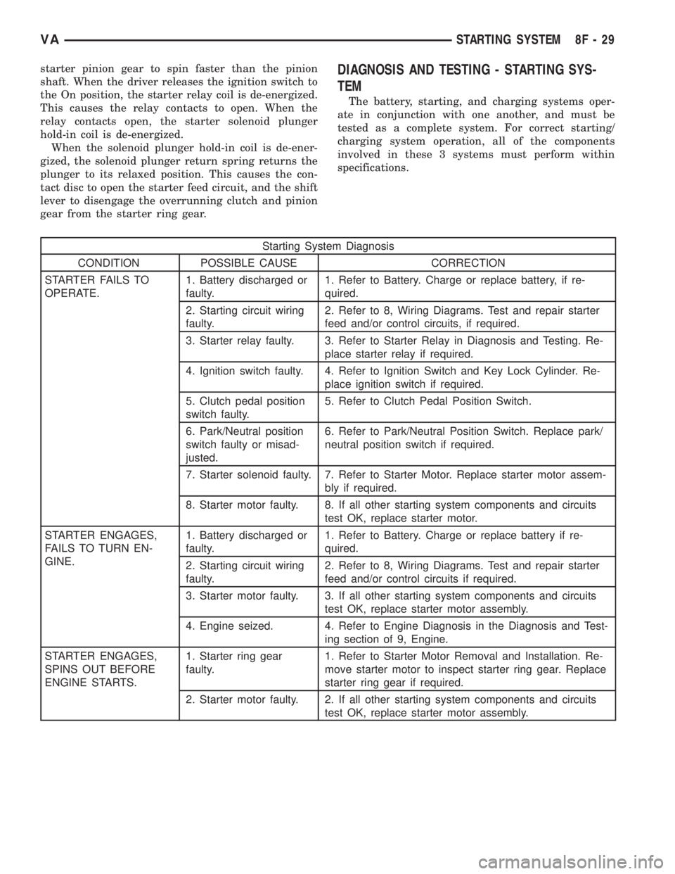
Starting System Diagnosis
CONDITION POSSIBLE CAUSE CORRECTION
STARTER FAILS TO
OPERATE.1. Battery discharged or
faulty.1. Refer to Battery. Charge or replace battery, if re-
quired.
2. Starting circuit wiring
faulty.2. Refer to 8, Wiring Diagrams. Test and repair starter
feed and/or control circuits, if required.
3. Starter relay faulty. 3. Refer to Starter Relay in Diagnosis and Testing. Re-
place starter relay if required.
4. Ignition switch faulty. 4. Refer to Ignition Switch and Key Lock Cylinder. Re-
place ignition switch if required.
5. Clutch pedal position
switch faulty.5. Refer to Clutch Pedal Position Switch.
6. Park/Neutral position
switch faulty or misad-
justed.6. Refer to Park/Neutral Position Switch. Replace park/
neutral position switch if required.
7. Starter solenoid faulty. 7. Refer to Starter Motor. Replace starter motor assem-
bly if required.
8. Starter motor faulty. 8. If all other starting system components and circuits
test OK, replace starter motor.
STARTER ENGAGES,
FAILS TO TURN EN-
GINE.1. Battery discharged or
faulty.1. Refer to Battery. Charge or replace battery if re-
quired.
2. Starting circuit wiring
faulty.2. Refer to 8, Wiring Diagrams. Test and repair starter
feed and/or control circuits if required.
3. Starter motor faulty. 3. If all other starting system components and circuits
test OK, replace starter motor assembly.
4. Engine seized. 4. Refer to Engine Diagnosis in the Diagnosis and Test-
ing section of 9, Engine.
STARTER ENGAGES,
SPINS OUT BEFORE
ENGINE STARTS.1. Starter ring gear
faulty.1. Refer to Starter Motor Removal and Installation. Re-
move starter motor to inspect starter ring gear. Replace
starter ring gear if required.
2. Starter motor faulty. 2. If all other starting system components and circuits
test OK, replace starter motor assembly.
VASTARTING SYSTEM 8F - 29
Page 895 of 2305
Starting System Diagnosis
CONDITION POSSIBLE CAUSE CORRECTION
STARTER DOES NOT
DISENGAGE.1. Starter motor improp-
erly installed.1. Refer to Starter Motor Removal and Installation.
Tighten starter mounting hardware to correct torque
specifications.
2. Starter relay faulty. 2. Refer to Starter Relay Diagnosis and Testing. Re-
place starter relay if required.
3. Ignition switch faulty. 3. Refer to Ignition Switch and Key Lock Cylinder. Re-
place ignition switch if required.
4. Starter motor faulty. 4. If all other starting system components and circuits
test OK, replace starter motor.
INSPECTION
For complete starter wiring circuit diagrams, refer
to 8, Wiring Diagrams. Before removing any unit
from starting system for repair or diagnosis, perform
the following inspections:
WARNING: ON VEHICLES EQUIPPED WITH AIR-
BAGS, REFER TO 8, PASSIVE RESTRAINT SYS-
TEMS, BEFORE ATTEMPTING ANY STEERING
WHEEL, STEERING COLUMN, OR INSTRUMENT
PANEL COMPONENT DIAGNOSIS OR SERVICE.
FAILURE TO TAKE THE PROPER PRECAUTIONS
COULD RESULT IN ACCIDENTAL AIRBAG DEPLOY-
MENT AND POSSIBLE PERSONAL INJURY.
²Battery- Visually inspect battery for indica-
tions of physical damage and loose or corroded cable
connections. Determine state-of-charge and cranking
capacity of battery. Charge or replace battery if
required. Refer toBatteryin 8, Battery.
²Ignition Switch- Visually inspect ignition
switch for indications of physical damage and loose
or corroded wire harness connections. Refer toIgni-
tion Switch and Key Lock Cylinder.
²Park/Neutral Position Switch- Visually
inspect park/neutral position switch for indications of
physical damage and loose or corroded wire harness
connections. Refer toPark/Neutral Position
Switchin 21, Transmission.
²Starter Relay- Visually inspect starter relay
for indications of physical damage and loose or cor-
roded wire harness connections.
²Starter Motor- Visually inspect starter motor
for indications of physical damage and loose or cor-
roded wire harness connections.
²Starter Solenoid- Visually inspect starter sole-
noid for indications of physical damage and loose or
corroded wire harness connections.
²Wiring- Visually inspect wire harnesses for
damage or corrosion. Repair or replace any faulty
wiring, as required. Refer to 8, Wiring Diagrams.
TESTING
COLD CRANKING TEST
For complete starter wiring circuit diagrams, refer
to 8, Wiring Diagrams. The battery must be fully-
charged and load-tested before proceeding. Refer to
Batteryin 8, Battery.
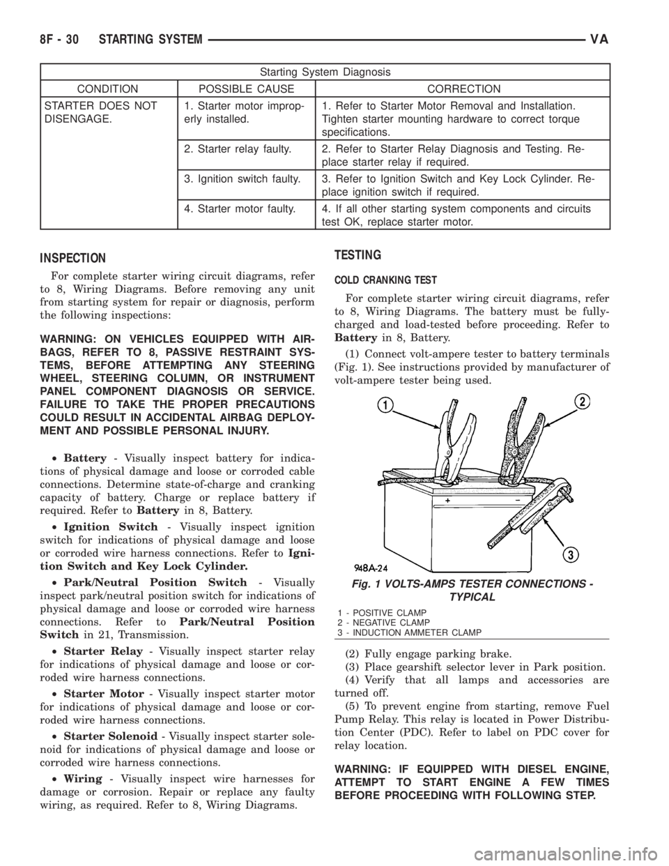
(1) Connect volt-ampere tester to battery terminals
(Fig. 1). See instructions provided by manufacturer of
volt-ampere tester being used.
(2) Fully engage parking brake.
(3) Place gearshift selector lever in Park position.
(4) Verify that all lamps and accessories are
turned off.
(5) To prevent engine from starting, remove Fuel
Pump Relay. This relay is located in Power Distribu-
tion Center (PDC). Refer to label on PDC cover for
relay location.
WARNING: IF EQUIPPED WITH DIESEL ENGINE,
ATTEMPT TO START ENGINE A FEW TIMES
BEFORE PROCEEDING WITH FOLLOWING STEP.
Fig. 1 VOLTS-AMPS TESTER CONNECTIONS -
TYPICAL
1 - POSITIVE CLAMP
2 - NEGATIVE CLAMP
3 - INDUCTION AMMETER CLAMP
8F - 30 STARTING SYSTEMVA
Page 896 of 2305
(6) Rotate and hold ignition switch in Start posi-
tion. Note cranking voltage and current (amperage)
draw readings shown on volt-ampere tester.
(a) If voltage reads below 9.6 volts, refer to
Starter Motorin Diagnosis and Testing. If starter
motor is OK, refer toEngine Diagnosisin 9,
Engine for further testing of engine. If starter
motor is not OK, replace faulty starter motor.
(b) If voltage reads above 9.6 volts and current
(amperage) draw reads below specifications, refer
toFeed Circuit Testin this section.
(c) If voltage reads 12.5 volts or greater and
starter motor does not turn, refer toControl Cir-
cuit Testingin this section.
(d) If voltage reads 12.5 volts or greater and
starter motor turns very slowly, refer toFeed Cir-
cuit Testin this section.
NOTE: A cold engine will increase starter current
(amperage) draw reading, and reduce battery volt-
age reading.
FEED CIRCUIT TEST
The starter feed circuit test (voltage drop method)
will determine if there is excessive resistance in
high-amperage feed circuit. For complete starter wir-
ing circuit diagrams, refer 8, Wiring Diagrams.
When performing these tests, it is important to
remember that voltage drop is giving an indication of
resistance between two points at which voltmeter
probes are attached.
Example:When testing resistance of positive bat-
tery cable, touch voltmeter leads to positive battery
cable clamp and cable connector at starter solenoid.
If you probe positive battery terminal post and cable
connector at starter solenoid, you are reading com-
bined voltage drop in positive battery cable clamp-to-
terminal post connection and positive battery cable.
The following operation will require a voltmeter
accurate to 1/10 (0.10) volt. Before performing tests,
be certain that following procedures are accom-
plished:
²Battery is fully-charged and load-tested. Refer to
Batteryin 8, Battery.
²Fully engage parking brake.
²Place gearshift selector lever in Park position.
²Verify that all lamps and accessories are turned
off.
²To prevent engine from starting, remove Fuel
Pump Relay. This relay is located in Power Distribu-
tion Center (PDC). Refer to label on PDC cover for
relay location.
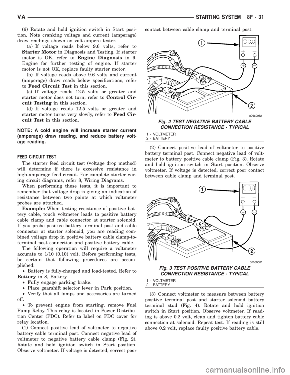
(1) Connect positive lead of voltmeter to negative
battery cable terminal post. Connect negative lead of
voltmeter to negative battery cable clamp (Fig. 2).
Rotate and hold ignition switch in Start position.
Observe voltmeter. If voltage is detected, correct poorcontact between cable clamp and terminal post.
(2) Connect positive lead of voltmeter to positive
battery terminal post. Connect negative lead of volt-
meter to battery positive cable clamp (Fig. 3). Rotate
and hold ignition switch in Start position. Observe
voltmeter. If voltage is detected, correct poor contact
between cable clamp and terminal post.
(3) Connect voltmeter to measure between battery
positive terminal post and starter solenoid battery
terminal stud (Fig. 4). Rotate and hold ignition
switch in Start position. Observe voltmeter. If read-
ing is above 0.2 volt, clean and tighten battery cable
connection at solenoid. Repeat test. If reading is still
above 0.2 volt, replace faulty positive battery cable.
Fig. 2 TEST NEGATIVE BATTERY CABLE
CONNECTION RESISTANCE - TYPICAL
1 - VOLTMETER
2 - BATTERY
Fig. 3 TEST POSITIVE BATTERY CABLE
CONNECTION RESISTANCE - TYPICAL
1 - VOLTMETER
2 - BATTERY
VASTARTING SYSTEM 8F - 31
Page 897 of 2305
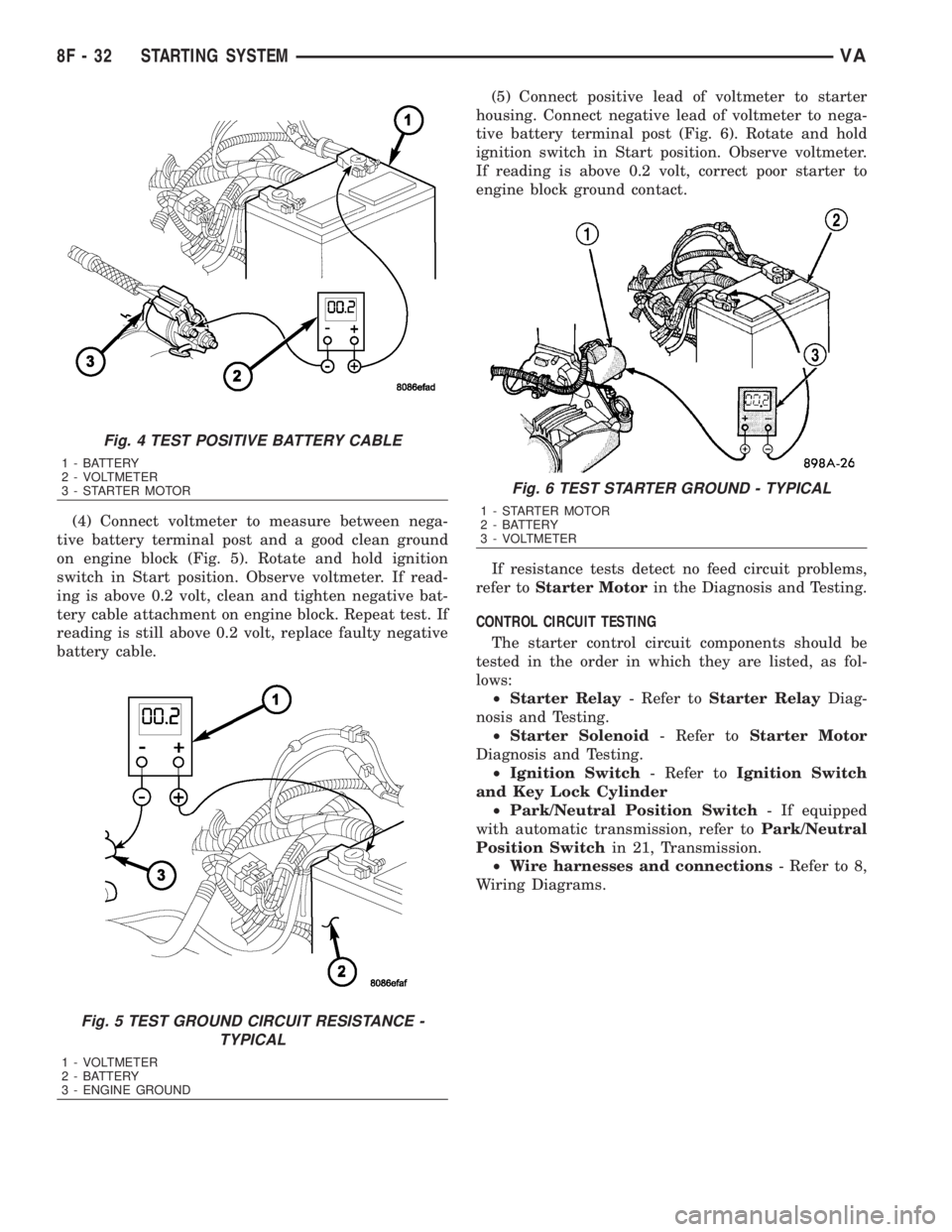
(4) Connect voltmeter to measure between nega-
tive battery terminal post and a good clean ground
on engine block (Fig. 5). Rotate and hold ignition
switch in Start position. Observe voltmeter. If read-
ing is above 0.2 volt, clean and tighten negative bat-
tery cable attachment on engine block. Repeat test. If
reading is still above 0.2 volt, replace faulty negative
battery cable.(5) Connect positive lead of voltmeter to starter
housing. Connect negative lead of voltmeter to nega-
tive battery terminal post (Fig. 6). Rotate and hold
ignition switch in Start position. Observe voltmeter.
If reading is above 0.2 volt, correct poor starter to
engine block ground contact.
If resistance tests detect no feed circuit problems,
refer toStarter Motorin the Diagnosis and Testing.
CONTROL CIRCUIT TESTING
The starter control circuit components should be
tested in the order in which they are listed, as fol-
lows:
²Starter Relay- Refer toStarter RelayDiag-
nosis and Testing.
²Starter Solenoid- Refer toStarter Motor
Diagnosis and Testing.
²Ignition Switch- Refer toIgnition Switch
and Key Lock Cylinder
²Park/Neutral Position Switch- If equipped
with automatic transmission, refer toPark/Neutral
Position Switchin 21, Transmission.
²Wire harnesses and connections- Refer to 8,
Wiring Diagrams.
Fig. 4 TEST POSITIVE BATTERY CABLE
1 - BATTERY
2 - VOLTMETER
3 - STARTER MOTOR
Fig. 5 TEST GROUND CIRCUIT RESISTANCE -
TYPICAL
1 - VOLTMETER
2 - BATTERY
3 - ENGINE GROUND
Fig. 6 TEST STARTER GROUND - TYPICAL
1 - STARTER MOTOR
2 - BATTERY
3 - VOLTMETER
8F - 32 STARTING SYSTEMVA
Page 903 of 2305
relays which allows battery current to flow to the
rear window defogger grid lines. The heated grid
lines heat the rear glass to help clear the rear win-
dow surfaces of fog or frost.
The electric backlight (EBL) system is controlled
by the EBL timing circuity, which is integral to the
rear window defogger module. A yellow indicator in
the switch will illuminate to indicate when the EBL
system is turned on.
NOTE: The EBL system turns off automatically after
approximately 10 minutes of initial operation. Each
following activation cycle of the EBL system will
last approximately five minutes.
The EBL system will be automatically turned off
after a programmed time interval of about ten min-
utes. After the initial time interval has expired, if the
rear window defogger switch is pressed to the On
position again during the same ignition cycle, the
EBL system will automatically turn off after about
five minutes.
The EBL system will automatically shut off if the
ignition switch is turned to the Off position, or it can
be turned off manually by pressing the defogger
switch a second time.
DIAGNOSIS AND TESTING
ELECTRIC BACKLIGHT (EBL) SYSTEM
NOTE: Illumination of the defogger switch indicator
lamp means that there is electrical current available
at the output of the rear window defogger logic cir-
cuitry, but does not confirm that the electrical cur-
rent is reaching the rear glass heating grid lines.
NOTE: For circuit descriptions and diagrams of the
EBL system, refer to 8W - WIRING DIAGRAM
INFORMATION.
Operation of the electrical backlight (EBL) system
can be confirmed by the following:
(1) Turn the ignition switch to the On position. Set
the rear window defogger switch in the On position.
The rear window defogger operation can be checked
by feeling the rear window glass. A distinct difference
in temperature between the grid lines and the adja-
cent clear glass should be detected within three to
four minutes of operation.
(2) If a temperature difference is not detected, use
a 12-volt DC voltmeter and contact the rear glass
heating grid terminal B with the negative lead, and
terminal A with the positive lead (Fig. 2). The volt-
meter should read battery voltage. If the voltmeter
does not read battery voltage, check the following:²Confirm that the ignition switch is in the On
position.
²Make sure that the rear glass heating grid feed
wires and ground wires are connected to the window
terminals. Confirm that the ground wires have conti-
nuity to ground.
²Check that fuse 7 (15 amp) in fuse block #1 and
fuse 10 (30 amp) in the fuse/relay block are OK. The
fuses must be tight in there receptacles and all elec-
trical connections must be secure.
(3) When the above steps have been completed and
the rear glass heating grid is still inoperative, one or
more of the following is faulty.
²Rear window defogger switch in the instrument
panel.
²Rear window defogger (EBL) relays in the fuse/
relay block.
²Rear window defogger (EBL) relay control circu-
ity in the rear window defogger module.
²Check for a loose wire connector or a wire
pushed out of a connector.
²Rear window grid lines (all grid lines would
have to be broken, or the power feed or ground wire
not connected, for the entire heating grid to be inop-
erative).
(4) If the system operation has been verified but
the defogger switch indicator does not illuminate,
check for voltage at the defogger indicator from the
rear window defogger module when the defogger
switch is activated. If power is present, replace the
rear window defogger switch.
(5) If broken defogger grid lines are suspected, use
a 12-volt DC voltmeter and contact terminal B with
the negative lead and each rear glass heating grid
line at it's mid-point with the positive lead. The volt-
meter should read approximately 6 volts at each grid
line mid-point C. If the voltmeter does not read
approximately 6 volts, repair the open grid line(s)
(Refer to 8 - ELECTRICAL/HEATED GLASS/REAR
WINDOW DEFOGGER GRID - STANDARD PROCE-
DURE).
8G - 2 HEATED GLASSVA
Page 905 of 2305
²The coil ground terminal (86) is hardwired to
ground point G202.
²The coil battery terminal (85) receives a battery
current input from the rear window defogger module
when the rear window defogger switch is energized.
²The normally open terminal (87) provides a bat-
tery current output to the rear window defogger grid
lines through the relay output circuit only when the
rear window defogger relay coil is energized.
²The normally closed terminal (87A) is not con-
nected to any circuit in this application, but provides
a battery current output only when the rear window
defogger relay coil is de-energized.
The left and right EBL relays cannot be repaired
and, if faulty or damaged, they must be replaced.
Refer to the appropriate wiring information for diag-
nosis and testing of the EBL relays and for complete
rear window defogger system wiring diagrams.
REMOVAL
(1) Disconnect and isolate the negative battery
cable.
(2) Remove the cover from the fuse/relay block
(Fig. 4).
NOTE: Refer to the fuse and relay map located on
the inner surface of the fuse/relay block cover for
the left and right rear window defogger (EBL) relay
locations.
(3) Remove the EBL relays from the fuse/relay
block as required.
INSTALLATION
NOTE: Refer to the fuse and relay map located on
the inner surface of the fuse/relay block cover for
the left and right rear window defogger (EBL) relay
locations.
(1) Position the rear window defogger (EBL) relays
as required into their proper receptacles in the fuse/
relay block.
(2) Align the EBL relay terminals with the termi-
nal cavities in the fuse/relay block receptacles.
(3) Push down firmly on the EBL relays until the
terminals are fully seated in the terminal cavities in
the fuse/relay block receptacles.
(4) Install the cover onto the fuse/relay block.
(5) Reconnect the negative battery cable.
REAR WINDOW DEFOGGER
SWITCH
DESCRIPTION
The rear window defogger switch is mounted in the
instrument panel to the right of the steering wheel
(Fig. 5). The rear window defogger switch contains a
yellow indicator lamp that illuminates when the rear
window defogger (EBL) system is activated.
The rear window defogger switch and the defogger
switch indicator cannot be repaired and, if faulty or
damaged, the rear window defogger switch must be
replaced.
OPERATION
A yellow indicator lamp will illuminate when the
rear window defogger switch is activated. The switch
Fig. 4 Rear Window Defogger (EBL) Relays
1 - DRIVERS SEAT
2 - FUSE/RELAY BLOCKFig. 5 Rear Window Defogger Switch
1 - REAR WINDOW DEFOGGER SWITCH
2 - INSTRUMENT PANEL
8G - 4 HEATED GLASSVA
Page 906 of 2305
energizes the timing circuit of the rear window defog-
ger module which then activates the rear window
defogger (EBL) relays. The EBL relays controls the
current flow to the rear window defogger grids. The
EBL system will operate for approximately five min-
utes or until the rear window defogger switch or igni-
tion switch is turned off. Refer to 8 - ELECTRICAL/
HEATED GLASS - DIAGNOSIS AND TESTING for
diagnosis and testing of the rear window defogger
switch.
The rear window defogger switch cannot be
repaired and, if faulty or damaged, it must be
replaced.
DIAGNOSIS AND TESTING
REAR WINDOW DEFOGGER SWITCH
WARNING: On vehicles equipped with airbags, dis-
able the airbag system before attempting any steer-
ing wheel, steering column, or instrument panel
component diagnosis or service. Disconnect and
isolate the battery negative (ground) cable, then
wait two minutes for the airbag system capacitor to
discharge before performing further diagnosis or
service. This is the only sure way to disable the air-
bag system. Failure to take the proper precautions
could result in an accidental airbag deployment and
possible personal injury.
NOTE: The rear window defogger switch may be
tested in the vehicle or out of the vehicle, on a
bench.
NOTE: For circuit descriptions and diagrams of the
rear window defogger system, refer to 8W - WIRING
DIAGRAM INFORMATION.
(1) Remove the rear window defogger switch from
the instrument panel, but leave the switch connected
(Refer to 8 - ELECTRICAL/HEATED GLASS/REAR
WINDOW DEFOGGER SWITCH - REMOVAL).
(2) Turn the ignition switch ON.
(3) Using a voltmeter, check for battery voltage at
Pin 3 of the rear window defogger switch (Fig. 6).
(a) If OK, go to Step 4.
(b) If NOT OK, check fuse 7 (15 amp) in fuse
block #1. If fuse is OK, check the wiring circuits.
Refer to 8W - WIRING DIAGRAM INFORMA-
TION.
(4) Check Pin 7, with defogger switch in the On
position there should be battery voltage and, no volt-
age with the switch in the Off position.
(a) If OK, go to Step 5.(b) If NOT OK, no voltage in the On position or
voltage in the Off position, replace the rear window
defogger switch.
(5) Press the defogger switch to the On position.
The indicator lamp should come on and remain on
for approximately 5 minutes.
(a) If OK, install the rear window defogger
switch (Refer to 8 - ELECTRICAL/HEATED
GLASS/REAR WINDOW DEFOGGER SWITCH -
INSTALLATION).
(b) If NOT OK, go to Step 6.
(6) Check Pin 9, with defogger switch in the On
position there should be battery voltage.
(a) If OK, go to Step 7.
(b) If NOT OK, check the wiring circuits. Refer
to 8W - WIRING DIAGRAM INFORMATION.
(7) Check Pin 10 for a good ground.
(a) If OK, replace the rear window defogger
switch.
(b) If NOT OK, check the wiring circuits. Refer
to 8W - WIRING DIAGRAM INFORMATION.
Fig. 6 Rear Window Defogger Switch Connector
VAHEATED GLASS 8G - 5
Page 910 of 2305

HEATED MIRRORS
TABLE OF CONTENTS
page page
HEATED MIRRORS
DESCRIPTION..........................9OPERATION............................9
HEATED MIRRORS
DESCRIPTION
The available heated outside rear view mirror sys-
tem is operational anytime the ignition switch is in
the Run position (Fig. 1). When energized, each of
these heater grids produce heat to help clear the out-
side mirrors of ice, snow, or fog.
OPERATION
The electric heater grid located behind the glass of
each of the outside rear view mirrors is energized
when the ignition switch is turned to the Run posi-
tion. The heater grids heat the glass surface of the
outside rear view mirrors.
If the outside mirror heating grids are inoperative,
refer to 8W - WIRING DIAGRAM INFORMATION.
The heating grid behind each outside mirror glass
cannot be repaired and, if faulty or damaged, the
mirror glass must be replaced (Refer to 23 - BODY/
EXTERIOR/MIRROR-SIDE VIEW - GLASS -
REMOVAL).
Fig. 1 SIDE VIEW MIRROR - GLASS
1 - MIRROR GLASS
2 - ELECTRICAL CONNECTORS
3 - GUIDES
VAHEATED MIRRORS 8G - 9