2006 MERCEDES-BENZ SPRINTER diagram
[x] Cancel search: diagramPage 995 of 2305

and to the supplemental restraint system compo-
nents through the use of a combination of soldered
splices, splice block connectors, and many different
types of wire harness terminal connectors and insu-
lators. Refer to the appropriate wiring information.
The wiring information includes wiring diagrams,
proper wire and connector repair procedures, further
details on wire harness routing and retention, as well
as pin-out and location views for the various wire
harness connectors, splices and grounds.
OPERATION
ACTIVE RESTRAINTS
The primary passenger restraints in this or any
other vehicle are the standard equipment factory-in-
stalled seat belts. Seat belts are referred to as an
active restraint because the vehicle occupants are
required to physically fasten and properly adjust
these restraints in order to benefit from them. See
the owner's manual in the vehicle glove box for more
information on the features, use and operation of all
of the factory-installed active restraints.
PASSIVE RESTRAINTS
The passive restraints are referred to as a supple-
mental restraint system because they were designed
and are intended to enhance the protection for the
occupants of the vehicleonlywhen used in conjunc-
tion with the seat belts. They are referred to as pas-
sive restraints because the vehicle occupants are not
required to do anything to make them operate; how-
ever, the vehicle occupants must be wearing their
seat belts in order to obtain the maximum safety
benefit from the factory-installed supplemental
restraint system.
The supplemental restraint system electrical cir-
cuits are continuously monitored and controlled by a
microprocessor and software contained within the
Airbag Control Module (ACM). An airbag indicator in
the ElectroMechanical Instrument Cluster (EMIC)
illuminates for about four seconds as a bulb test each
time the ignition switch is turned to the On or Start
positions. Following the bulb test, the airbag indica-
tor is turned on or off by the ACM to indicate the
status of the supplemental restraint system. If the
airbag indicator comes on either solid or flashing at
any time other than during the bulb test, it indicates
that there is a problem in the supplemental restraint
system electrical circuits. Such a problem may cause
airbags not to deploy when required, or to deploy
when not required.
Deployment of the supplemental restraints
depends upon the angle and severity of an impact.
Deployment is not based upon vehicle speed; rather,
deployment is based upon the rate of deceleration as
measured by the forces of gravity (G force) upon the
impact sensor(s). When an impact is severe enough,the microprocessor in the ACM signals the inflator of
the appropriate airbag units to deploy their airbag
cushions. The front seat belt tensioners are provided
with a deployment signal by the ACM in conjunction
with the driver and passenger airbags.
During a frontal vehicle impact, the knee blockers
work in concert with properly fastened and adjusted
seat belts to restrain both the driver and the front
seat passenger in the proper position for an airbag
deployment. The knee blockers also absorb and dis-
tribute the crash energy from the driver and the
front seat passenger to the structure of the instru-
ment panel. The seat belt tensioners remove the
slack from the front seat belts to provide further
assurance that the driver and front seat passenger
are properly positioned and restrained for an airbag
deployment.
Typically, the vehicle occupants recall more about
the events preceding and following a collision than
they do of an airbag deployment itself. This is
because the airbag deployment and deflation occur so
rapidly. In a typical 48 kilometer-per-hour (30 mile-
per-hour) barrier impact, from the moment of impact
until the airbags are fully inflated takes only a few
milliseconds. Within one to two seconds from the
moment of impact, the airbags are almost entirely
deflated. The times cited for these events are approx-
imations, which apply only to a barrier impact at the
given speed. Actual times will vary somewhat,
depending upon the vehicle speed, impact angle,
severity of the impact, and the type of collision.
When the ACM monitors a problem in any of the
airbag system circuits or components, including the
seat belt tensioners, it stores a fault code or Diagnos-
tic Trouble Code (DTC) in its memory circuit and
sends a hard wired output to the EMIC to turn on
the airbag indicator. If the EMIC detects a problem
in the airbag indicator or airbag indicator circuit, the
cluster will flash the seatbelt indicator on and off.
Proper testing of the supplemental restraint system
components as well as the retrieval or erasure of a
DTC from the ACM requires the use of a diagnostic
scan tool. Refer to the appropriate diagnostic infor-
mation.
See the owner's manual in the vehicle glove box for
more information on the features, use and operation
of all of the factory-installed passive restraints.
8O - 4 RESTRAINTSVA
Page 1049 of 2305

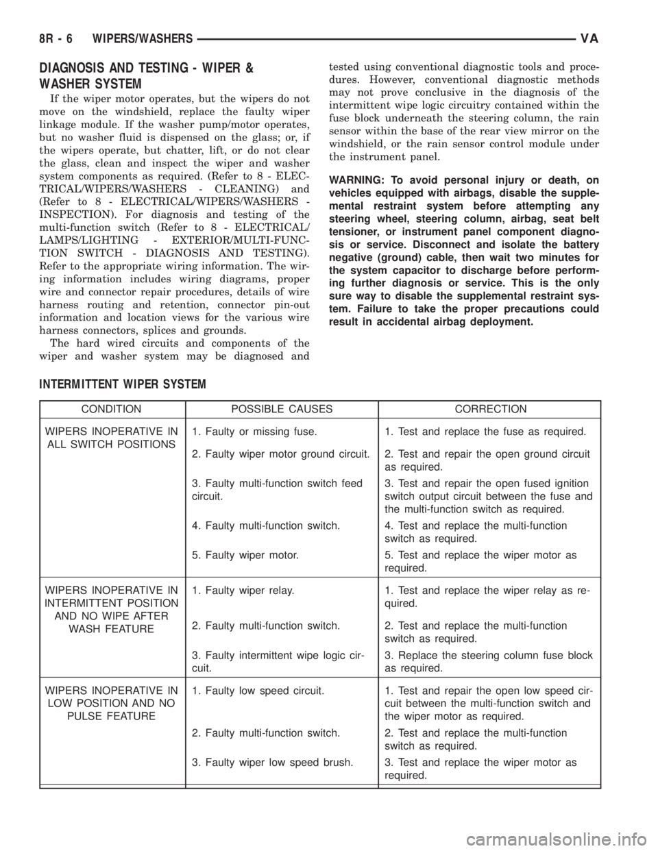
DIAGNOSIS AND TESTING - WIPER &
WASHER SYSTEM
If the wiper motor operates, but the wipers do not
move on the windshield, replace the faulty wiper
linkage module. If the washer pump/motor operates,
but no washer fluid is dispensed on the glass; or, if
the wipers operate, but chatter, lift, or do not clear
the glass, clean and inspect the wiper and washer
system components as required. (Refer to 8 - ELEC-
TRICAL/WIPERS/WASHERS - CLEANING) and
(Refer to 8 - ELECTRICAL/WIPERS/WASHERS -
INSPECTION). For diagnosis and testing of the
multi-function switch (Refer to 8 - ELECTRICAL/
LAMPS/LIGHTING - EXTERIOR/MULTI-FUNC-
TION SWITCH - DIAGNOSIS AND TESTING).
Refer to the appropriate wiring information. The wir-
ing information includes wiring diagrams, proper
wire and connector repair procedures, details of wire
harness routing and retention, connector pin-out
information and location views for the various wire
harness connectors, splices and grounds.
The hard wired circuits and components of the
wiper and washer system may be diagnosed andtested using conventional diagnostic tools and proce-
dures. However, conventional diagnostic methods
may not prove conclusive in the diagnosis of the
intermittent wipe logic circuitry contained within the
fuse block underneath the steering column, the rain
sensor within the base of the rear view mirror on the
windshield, or the rain sensor control module under
the instrument panel.
WARNING: To avoid personal injury or death, on
vehicles equipped with airbags, disable the supple-
mental restraint system before attempting any
steering wheel, steering column, airbag, seat belt
tensioner, or instrument panel component diagno-
sis or service. Disconnect and isolate the battery
negative (ground) cable, then wait two minutes for
the system capacitor to discharge before perform-
ing further diagnosis or service. This is the only
sure way to disable the supplemental restraint sys-
tem. Failure to take the proper precautions could
result in accidental airbag deployment.
INTERMITTENT WIPER SYSTEM
CONDITION POSSIBLE CAUSES CORRECTION
WIPERS INOPERATIVE IN
ALL SWITCH POSITIONS1. Faulty or missing fuse. 1. Test and replace the fuse as required.
2. Faulty wiper motor ground circuit. 2. Test and repair the open ground circuit
as required.
3. Faulty multi-function switch feed
circuit.3. Test and repair the open fused ignition
switch output circuit between the fuse and
the multi-function switch as required.
4. Faulty multi-function switch. 4. Test and replace the multi-function
switch as required.
5. Faulty wiper motor. 5. Test and replace the wiper motor as
required.
WIPERS INOPERATIVE IN
INTERMITTENT POSITION
AND NO WIPE AFTER
WASH FEATURE1. Faulty wiper relay. 1. Test and replace the wiper relay as re-
quired.
2. Faulty multi-function switch. 2. Test and replace the multi-function
switch as required.
3. Faulty intermittent wipe logic cir-
cuit.3. Replace the steering column fuse block
as required.
WIPERS INOPERATIVE IN
LOW POSITION AND NO
PULSE FEATURE1. Faulty low speed circuit. 1. Test and repair the open low speed cir-
cuit between the multi-function switch and
the wiper motor as required.
2. Faulty multi-function switch. 2. Test and replace the multi-function
switch as required.
3. Faulty wiper low speed brush. 3. Test and replace the wiper motor as
required.
8R - 6 WIPERS/WASHERSVA
Page 1080 of 2305

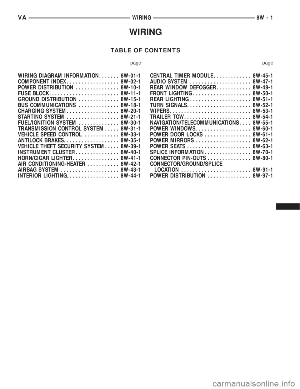
WIRING
TABLE OF CONTENTS
page page
WIRING DIAGRAM INFORMATION....... 8W-01-1
COMPONENT INDEX.................. 8W-02-1
POWER DISTRIBUTION............... 8W-10-1
FUSE BLOCK........................ 8W-11-1
GROUND DISTRIBUTION.............. 8W-15-1
BUS COMMUNICATIONS.............. 8W-18-1
CHARGING SYSTEM.................. 8W-20-1
STARTING SYSTEM.................. 8W-21-1
FUEL/IGNITION SYSTEM.............. 8W-30-1
TRANSMISSION CONTROL SYSTEM..... 8W-31-1
VEHICLE SPEED CONTROL............ 8W-33-1
ANTILOCK BRAKES................... 8W-35-1
VEHICLE THEFT SECURITY SYSTEM..... 8W-39-1
INSTRUMENT CLUSTER............... 8W-40-1
HORN/CIGAR LIGHTER................ 8W-41-1
AIR CONDITIONING-HEATER........... 8W-42-1
AIRBAG SYSTEM.................... 8W-43-1
INTERIOR LIGHTING.................. 8W-44-1CENTRAL TIMER MODULE............. 8W-45-1
AUDIO SYSTEM..................... 8W-47-1
REAR WINDOW DEFOGGER............ 8W-48-1
FRONT LIGHTING.................... 8W-50-1
REAR LIGHTING..................... 8W-51-1
TURN SIGNALS...................... 8W-52-1
WIPERS............................ 8W-53-1
TRAILER TOW....................... 8W-54-1
NAVIGATION/TELECOMMUNICATIONS.... 8W-55-1
POWER WINDOWS................... 8W-60-1
POWER DOOR LOCKS................ 8W-61-1
POWER MIRRORS................... 8W-62-1
POWER SEATS...................... 8W-63-1
SPLICE INFORMATION................ 8W-70-1
CONNECTOR PIN-OUTS............... 8W-80-1
CONNECTOR/GROUND/SPLICE
LOCATION........................ 8W-91-1
POWER DISTRIBUTION............... 8W-97-1 VAWIRING 8W - 1
Page 1082 of 2305

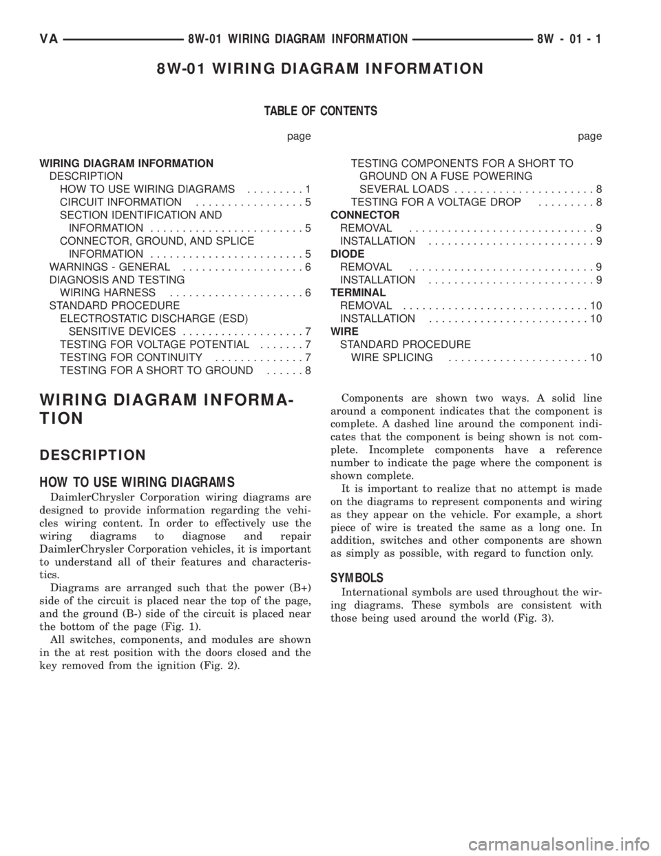
8W-01 WIRING DIAGRAM INFORMATION
TABLE OF CONTENTS
page page
WIRING DIAGRAM INFORMATION
DESCRIPTION
HOW TO USE WIRING DIAGRAMS.........1
CIRCUIT INFORMATION.................5
SECTION IDENTIFICATION AND
INFORMATION........................5
CONNECTOR, GROUND, AND SPLICE
INFORMATION........................5
WARNINGS - GENERAL...................6
DIAGNOSIS AND TESTING
WIRING HARNESS.....................6
STANDARD PROCEDURE
ELECTROSTATIC DISCHARGE (ESD)
SENSITIVE DEVICES...................7
TESTING FOR VOLTAGE POTENTIAL.......7
TESTING FOR CONTINUITY..............7
TESTING FOR A SHORT TO GROUND......8TESTING COMPONENTS FOR A SHORT TO
GROUND ON A FUSE POWERING
SEVERAL LOADS......................8
TESTING FOR A VOLTAGE DROP.........8
CONNECTOR
REMOVAL.............................9
INSTALLATION..........................9
DIODE
REMOVAL.............................9
INSTALLATION..........................9
TERMINAL
REMOVAL.............................10
INSTALLATION.........................10
WIRE
STANDARD PROCEDURE
WIRE SPLICING......................10
WIRING DIAGRAM INFORMA-
TION
DESCRIPTION
HOW TO USE WIRING DIAGRAMS
DaimlerChrysler Corporation wiring diagrams are
designed to provide information regarding the vehi-
cles wiring content. In order to effectively use the
wiring diagrams to diagnose and repair
DaimlerChrysler Corporation vehicles, it is important
to understand all of their features and characteris-
tics.
Diagrams are arranged such that the power (B+)
side of the circuit is placed near the top of the page,
and the ground (B-) side of the circuit is placed near
the bottom of the page (Fig. 1).
All switches, components, and modules are shown
in the at rest position with the doors closed and the
key removed from the ignition (Fig. 2).Components are shown two ways. A solid line
around a component indicates that the component is
complete. A dashed line around the component indi-
cates that the component is being shown is not com-
plete. Incomplete components have a reference
number to indicate the page where the component is
shown complete.
It is important to realize that no attempt is made
on the diagrams to represent components and wiring
as they appear on the vehicle. For example, a short
piece of wire is treated the same as a long one. In
addition, switches and other components are shown
as simply as possible, with regard to function only.
SYMBOLS
International symbols are used throughout the wir-
ing diagrams. These symbols are consistent with
those being used around the world (Fig. 3).
VA8W-01 WIRING DIAGRAM INFORMATION 8W - 01 - 1
Page 1083 of 2305

Fig. 1 WIRING DIAGRAM EXAMPLE 1
8W - 01 - 2 8W-01 WIRING DIAGRAM INFORMATIONVA
Page 1084 of 2305

Fig. 2 WIRING DIAGRAM EXAMPLE 2
VA8W-01 WIRING DIAGRAM INFORMATION 8W - 01 - 3
Page 1085 of 2305

Fig. 3 Wiring Diagram Symbols
8W - 01 - 4 8W-01 WIRING DIAGRAM INFORMATIONVA
Page 1086 of 2305

TERMINOLOGY
This is a list of terms and definitions used in the
wiring diagrams.
LHD.................Left Hand Drive Vehicles
RHD ...............Right Hand Drive Vehicles
ATX . . Automatic Transmissions-Front Wheel Drive
MTX . . . Manual Transmissions-Front Wheel Drive
AT....Automatic Transmissions-Rear Wheel Drive
MT .....Manual Transmissions-Rear Wheel Drive
SOHC...........Single Over Head Cam Engine
DOHC..........Double Over Head Cam Engine
Built-Up-Export....... Vehicles Built For Sale In
Markets Other Than North America
Except Built-Up-Export . Vehicles Built For Sale In
North America
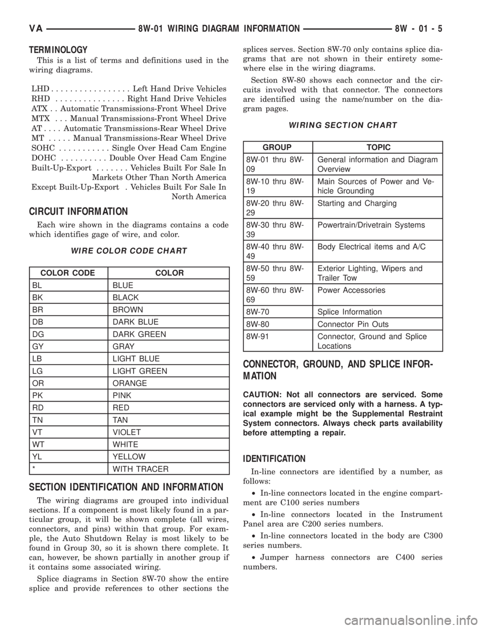
CIRCUIT INFORMATION
Each wire shown in the diagrams contains a code
which identifies gage of wire, and color.
WIRE COLOR CODE CHART
COLOR CODE COLOR
BL BLUE
BK BLACK
BR BROWN
DB DARK BLUE
DG DARK GREEN
GY GRAY
LB LIGHT BLUE
LG LIGHT GREEN
OR ORANGE
PK PINK
RD RED
TN TAN
VT VIOLET
WT WHITE
YL YELLOW
* WITH TRACER
SECTION IDENTIFICATION AND INFORMATION
The wiring diagrams are grouped into individual
sections. If a component is most likely found in a par-
ticular group, it will be shown complete (all wires,
connectors, and pins) within that group. For exam-
ple, the Auto Shutdown Relay is most likely to be
found in Group 30, so it is shown there complete. It
can, however, be shown partially in another group if
it contains some associated wiring.
Splice diagrams in Section 8W-70 show the entire
splice and provide references to other sections thesplices serves. Section 8W-70 only contains splice dia-
grams that are not shown in their entirety some-
where else in the wiring diagrams.
Section 8W-80 shows each connector and the cir-
cuits involved with that connector. The connectors
are identified using the name/number on the dia-
gram pages.
WIRING SECTION CHART
GROUP TOPIC
8W-01 thru 8W-
09General information and Diagram
Overview
8W-10 thru 8W-
19Main Sources of Power and Ve-
hicle Grounding
8W-20 thru 8W-
29Starting and Charging
8W-30 thru 8W-
39Powertrain/Drivetrain Systems
8W-40 thru 8W-
49Body Electrical items and A/C
8W-50 thru 8W-
59Exterior Lighting, Wipers and
Trailer Tow
8W-60 thru 8W-
69Power Accessories
8W-70 Splice Information
8W-80 Connector Pin Outs
8W-91 Connector, Ground and Splice
Locations
CONNECTOR, GROUND, AND SPLICE INFOR-
MATION
CAUTION: Not all connectors are serviced. Some
connectors are serviced only with a harness. A typ-
ical example might be the Supplemental Restraint
System connectors. Always check parts availability
before attempting a repair.
IDENTIFICATION
In-line connectors are identified by a number, as
follows:
²In-line connectors located in the engine compart-
ment are C100 series numbers
²In-line connectors located in the Instrument
Panel area are C200 series numbers.
²In-line connectors located in the body are C300
series numbers.
²Jumper harness connectors are C400 series
numbers.
VA8W-01 WIRING DIAGRAM INFORMATION 8W - 01 - 5