Page 313 of 2305
10.7 RAIN SENSOR SYSTEM
S
C
H
E
M
A
T
I
C
D
I
A
G
R
A
M
S
300
SCHEMATIC DIAGRAMS
Page 320 of 2305

TABLE OF CONTENTS - Continued
9.0 CONNECTOR PINOUTS.................................................83
BRAKE FLUID LEVEL SWITCH............................................83
BRAKE LAMP SWITCH C1 (EXCEPT ESP)..................................83
BRAKE LAMP SWITCH C2 (EXCEPT ESP) - BLACK..........................83
CONTROLLER ANTILOCK BRAKE.........................................84
INSTRUMENT CLUSTER C2 - WHITE......................................85
STEERING ANGLE SENSOR..............................................85
TCS SWITCH (ASR) - BLACK.............................................85
WHEEL SPEED SENSOR-LEFT FRONT....................................85
WHEEL SPEED SENSOR-LEFT REAR......................................86
WHEEL SPEED SENSOR-RIGHT FRONT...................................86
WHEEL SPEED SENSOR-RIGHT REAR....................................86
10.0 SCHEMATIC DIAGRAMS.................................................87
10.1BOSCH 5.7 ANTILOCK BRAKE SYSTEM ± ABS.........................87
iii
Page 371 of 2305

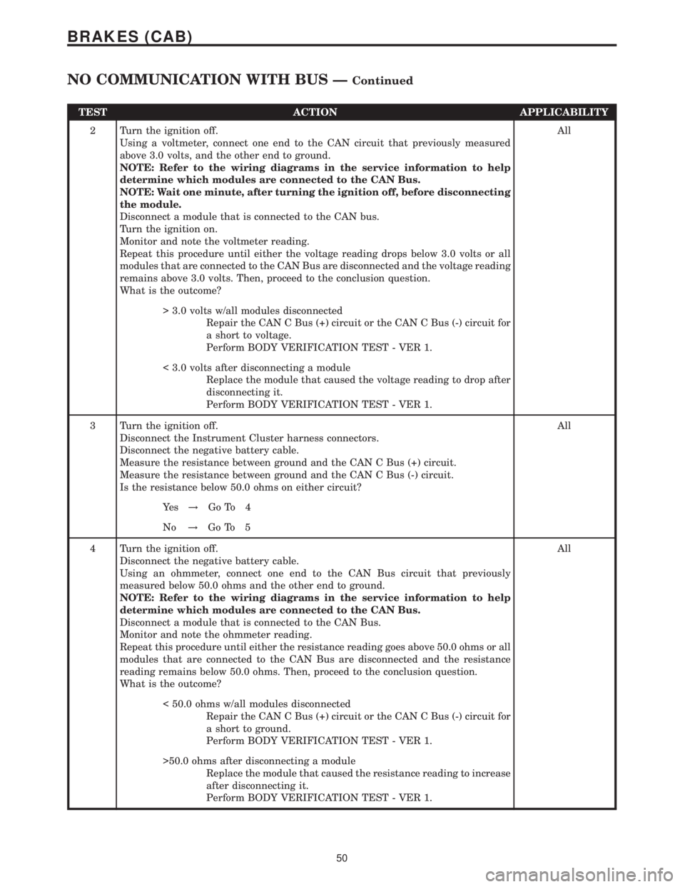
TEST ACTION APPLICABILITY
2 Turn the ignition off.
Using a voltmeter, connect one end to the CAN circuit that previously measured
above 3.0 volts, and the other end to ground.
NOTE: Refer to the wiring diagrams in the service information to help
determine which modules are connected to the CAN Bus.
NOTE: Wait one minute, after turning the ignition off, before disconnecting
the module.
Disconnect a module that is connected to the CAN bus.
Turn the ignition on.
Monitor and note the voltmeter reading.
Repeat this procedure until either the voltage reading drops below 3.0 volts or all
modules that are connected to the CAN Bus are disconnected and the voltage reading
remains above 3.0 volts. Then, proceed to the conclusion question.
What is the outcome?All
> 3.0 volts w/all modules disconnected
Repair the CAN C Bus (+) circuit or the CAN C Bus (-) circuit for
a short to voltage.
Perform BODY VERIFICATION TEST - VER 1.
< 3.0 volts after disconnecting a module
Replace the module that caused the voltage reading to drop after
disconnecting it.
Perform BODY VERIFICATION TEST - VER 1.
3 Turn the ignition off.
Disconnect the Instrument Cluster harness connectors.
Disconnect the negative battery cable.
Measure the resistance between ground and the CAN C Bus (+) circuit.
Measure the resistance between ground and the CAN C Bus (-) circuit.
Is the resistance below 50.0 ohms on either circuit?All
Ye s!Go To 4
No!Go To 5
4 Turn the ignition off.
Disconnect the negative battery cable.
Using an ohmmeter, connect one end to the CAN Bus circuit that previously
measured below 50.0 ohms and the other end to ground.
NOTE: Refer to the wiring diagrams in the service information to help
determine which modules are connected to the CAN Bus.
Disconnect a module that is connected to the CAN Bus.
Monitor and note the ohmmeter reading.
Repeat this procedure until either the resistance reading goes above 50.0 ohms or all
modules that are connected to the CAN Bus are disconnected and the resistance
reading remains below 50.0 ohms. Then, proceed to the conclusion question.
What is the outcome?All
< 50.0 ohms w/all modules disconnected
Repair the CAN C Bus (+) circuit or the CAN C Bus (-) circuit for
a short to ground.
Perform BODY VERIFICATION TEST - VER 1.
>50.0 ohms after disconnecting a module
Replace the module that caused the resistance reading to increase
after disconnecting it.
Perform BODY VERIFICATION TEST - VER 1.
50
BRAKES (CAB)
NO COMMUNICATION WITH BUS ÐContinued
Page 372 of 2305

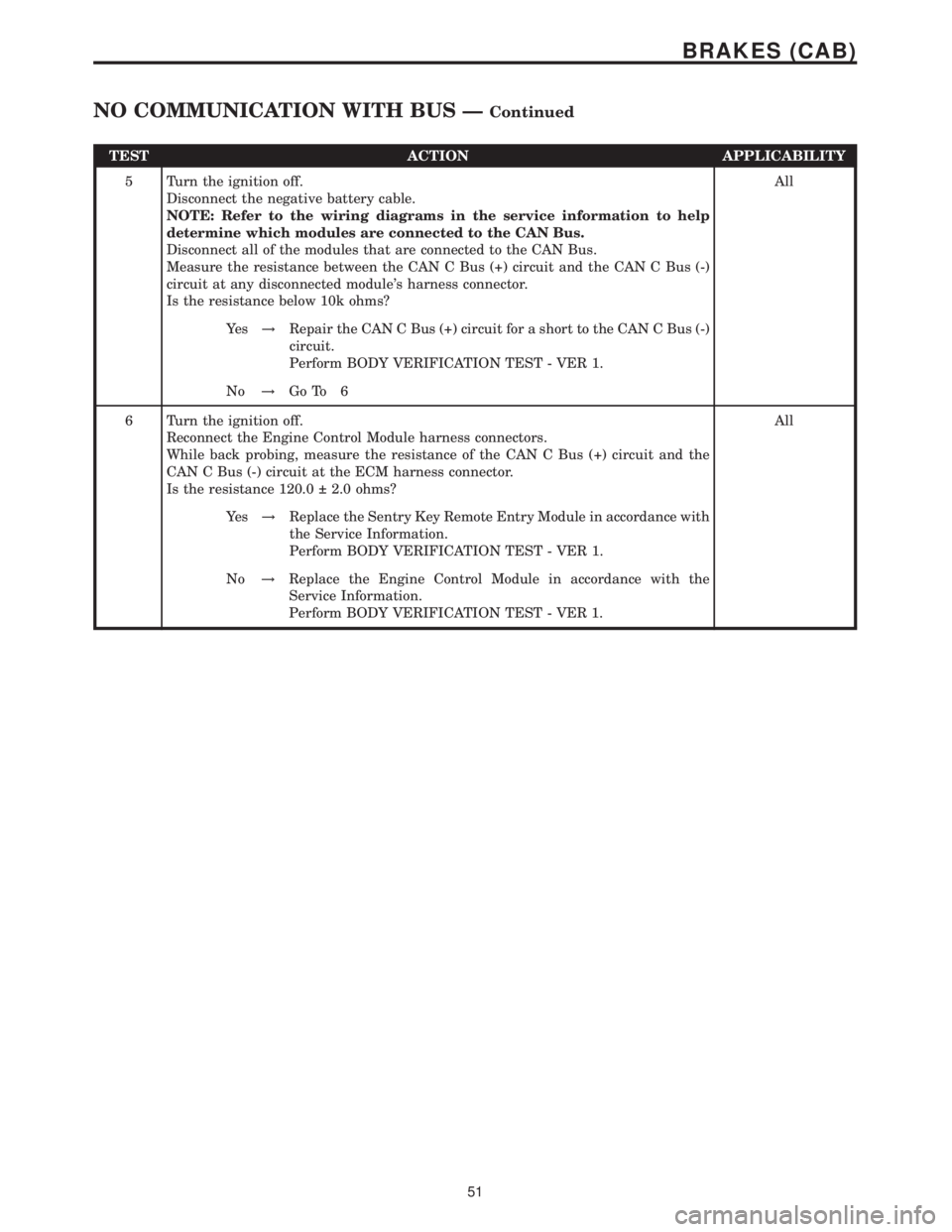
TEST ACTION APPLICABILITY
5 Turn the ignition off.
Disconnect the negative battery cable.
NOTE: Refer to the wiring diagrams in the service information to help
determine which modules are connected to the CAN Bus.
Disconnect all of the modules that are connected to the CAN Bus.
Measure the resistance between the CAN C Bus (+) circuit and the CAN C Bus (-)
circuit at any disconnected module's harness connector.
Is the resistance below 10k ohms?All
Ye s!Repair the CAN C Bus (+) circuit for a short to the CAN C Bus (-)
circuit.
Perform BODY VERIFICATION TEST - VER 1.
No!Go To 6
6 Turn the ignition off.
Reconnect the Engine Control Module harness connectors.
While back probing, measure the resistance of the CAN C Bus (+) circuit and the
CAN C Bus (-) circuit at the ECM harness connector.
Is the resistance 120.0 2.0 ohms?All
Ye s!Replace the Sentry Key Remote Entry Module in accordance with
the Service Information.
Perform BODY VERIFICATION TEST - VER 1.
No!Replace the Engine Control Module in accordance with the
Service Information.
Perform BODY VERIFICATION TEST - VER 1.
51
BRAKES (CAB)
NO COMMUNICATION WITH BUS ÐContinued
Page 408 of 2305
10.0 SCHEMATIC DIAGRAMS
10.1 BOSCH 5.7 ANTILOCK BRAKE SYSTEM ± ABS
S
C
H
E
M
A
T
I
C
D
I
A
G
R
A
M
S
87
SCHEMATIC DIAGRAMS
Page 422 of 2305
TABLE OF CONTENTS - Continued
KICK DOWN SWITCH - BLACK...........................................271
MASS AIR FLOW SENSOR - BLACK......................................271
OXYGEN SENSOR (OBD)...............................................271
FUSED IGNITION SWITCH RUN-START RELAY (RELAY BLOCK)..............273
SPEED CONTROL SWITCH.............................................273
WATER IN FUEL SENSOR - BLACK.......................................273
10.0 SCHEMATIC DIAGRAMS................................................275
10.1ENGINE CONTROL MODULE.......................................275
10.2ENGINE CONTROL MODULE.......................................276
11.0 CHARTS AND GRAPHS................................................277
xi
Page 427 of 2305

supply circuits). Refer to the appropriate wiring
diagrams to identify shared circuits.
abs brake message plausibility 1
abs brake message plausibility 2
abs brake signal can message implausible
abs can brake signal plausibility
abs can message missing or incorrect
abs dtc external quantity control fault present
abs steering angle sensor can message implausible
1
abs steering angle sensor can message implausible
2
acc pedal position sensor 1 ckt plausibility
acc pedal position sensor 1 ckt signal voltage too
high
acc pedal position sensor 1 ckt signal voltage too low
acc pedal position sensor 2 circuit plausibility
acc pedal position sensor 2 ckt signal voltage too
high
acc pedal position sensor 2 ckt signal voltage too low
acm circuit fault
acm circuit short to voltage
ambient air temperature signal voltage too high
ambient air temperature signal voltage too low
app sensor plausibility
atmospheric pressure sensor plausibility with boost
pressure sensor
atmospheric pressure sensor signal voltage too high
atmospheric pressure sensor signal voltage too low
automatic transmission coded as manual transmis-
sion
boost pressure servo motor circuit excessive current
boost pressure servo motor circuit open circuit
boost pressure servo motor circuit short circuit
boost pressure servo motor circuit short to ground
boost pressure servo motor excessive current
boost pressure servo motor open circuit
boost pressure servo motor short to ground
boost pressure servo motor short to ground
boost pressure servo motor short to voltage
boost pressure too high
boost pressure too low
camshaft position sensor circuit open circuit
camshaft position sensor circuit open or short cir-
cuit
can bus circuit interuption
can data bus -bus circuit fault
can message error
*checking the fuel pressure sensor circuits
*checking the fuel pressure solenoid circuits
*checking the fuel quantity solenoid circuits
*checking the power and grounds
ckp plausibility
cmp/ckp synchronization error
crankcase vent heater excessive current
crankcase vent heater open circuit
crankcase vent heater shorted to ground
crankcase vent heater shorted to voltagecrankshaft position sensor circuit lost signal
crankshaft position sensor circuit signal plausibil-
ity
crankshaft position sensor plausibility
cylinder #1 injector open circuit
cylinder #2 injector open circuit
cylinder #3 injector open circuit
cylinder #4 injector open circuit
cylinder #5 injector open circuit
cylinder 1-injector circuit excessive current
cylinder 1-injector circuit open or shorted to ground
cylinder 1-injector circuit shorted to voltage
cylinder 1-injector circuit shorted to ground
cylinder 2-injector circuit excessive current
cylinder 2-injector circuit open or shorted to ground
cylinder 2-injector circuit shorted to ground
cylinder 2-injector circuit shorted to voltage
cylinder 3-injector circuit excessive current
cylinder 3-injector circuit open or shorted to ground
cylinder 3-injector circuit shorted to ground
cylinder 3-injector circuit shorted to voltage
cylinder 4-injector circuit excessive current
cylinder 4-injector circuit open or shorted to ground
cylinder 4-injector circuit shorted to ground
cylinder 4-injector circuit shorted to voltage
cylinder 5-injector circuit excessive current
cylinder 5-injector circuit open or shorted to ground
cylinder 5-injector circuit shorted to ground
cylinder 5-injector circuit shorted to voltage
ecm a/d converter high
ecm a/d converter low
ecm a/d converter plausibility
ecm checksum error #1
ecm checksum error #2
ecm incorrect value
ecm injection quantity error
ecm injector monitoring 1
ecm injector monitoring 2
ecm injector monitoring 3
ecm injector monitoring 4
ecm injector output stage #1
ecm injector output stage #1 short circuit
ecm injector output stage #2
ecm injector output stage #2 short circuit
ecm injector undervoltage
ecm internal error
ecm internal error
ecm internal error
ecm internal error
ecm internal error 1
ecm internal error 1
ecm internal error 1
ecm internal error 1
ecm internal error 1
ecm internal error 2
ecm internal error 2
ecm internal error 2
ecm internal error 3
4
GENERAL INFORMATION
Page 435 of 2305

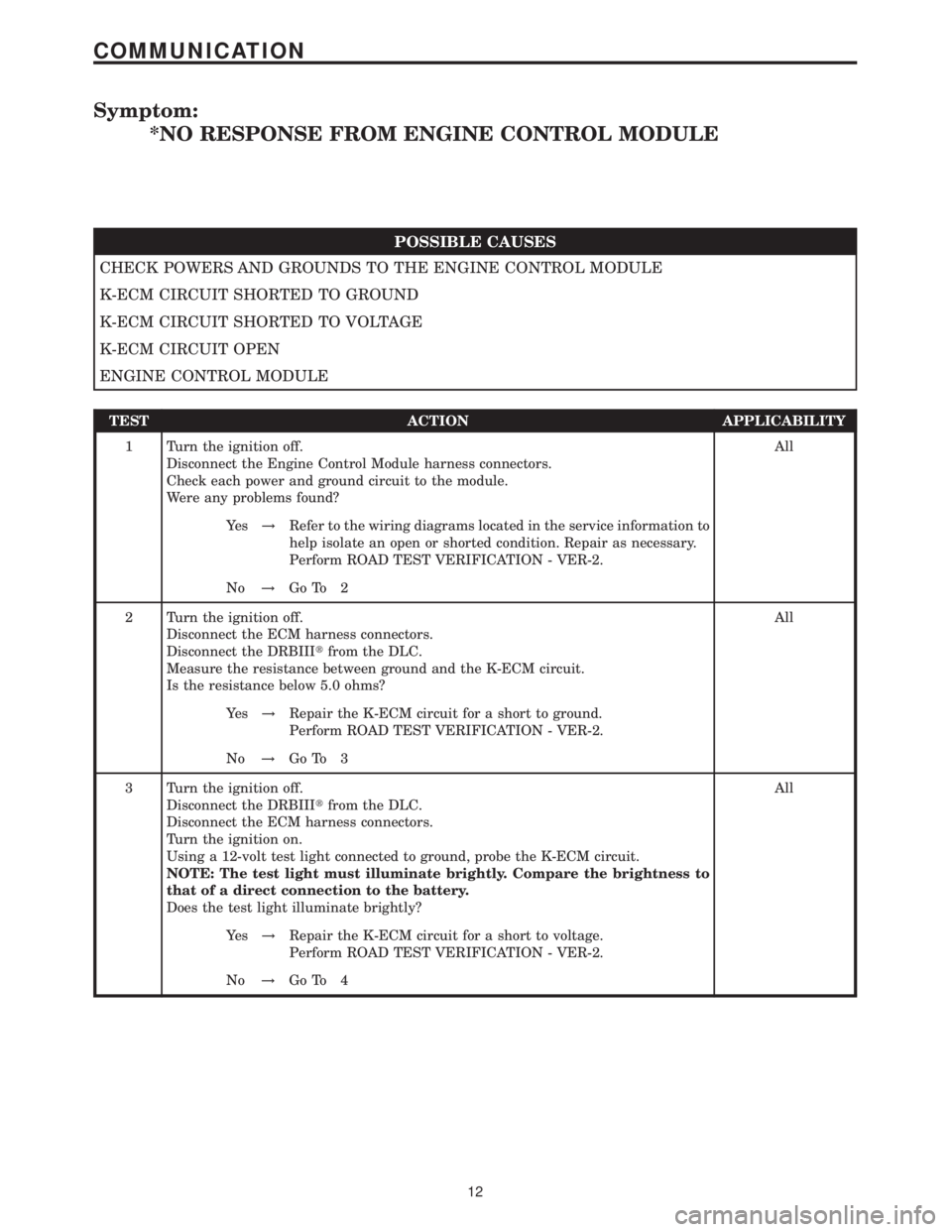
Symptom:
*NO RESPONSE FROM ENGINE CONTROL MODULE
POSSIBLE CAUSES
CHECK POWERS AND GROUNDS TO THE ENGINE CONTROL MODULE
K-ECM CIRCUIT SHORTED TO GROUND
K-ECM CIRCUIT SHORTED TO VOLTAGE
K-ECM CIRCUIT OPEN
ENGINE CONTROL MODULE
TEST ACTION APPLICABILITY
1 Turn the ignition off.
Disconnect the Engine Control Module harness connectors.
Check each power and ground circuit to the module.
Were any problems found?All
Ye s!Refer to the wiring diagrams located in the service information to
help isolate an open or shorted condition. Repair as necessary.
Perform ROAD TEST VERIFICATION - VER-2.
No!Go To 2
2 Turn the ignition off.
Disconnect the ECM harness connectors.
Disconnect the DRBIIItfrom the DLC.
Measure the resistance between ground and the K-ECM circuit.
Is the resistance below 5.0 ohms?All
Ye s!Repair the K-ECM circuit for a short to ground.
Perform ROAD TEST VERIFICATION - VER-2.
No!Go To 3
3 Turn the ignition off.
Disconnect the DRBIIItfrom the DLC.
Disconnect the ECM harness connectors.
Turn the ignition on.
Using a 12-volt test light connected to ground, probe the K-ECM circuit.
NOTE: The test light must illuminate brightly. Compare the brightness to
that of a direct connection to the battery.
Does the test light illuminate brightly?All
Ye s!Repair the K-ECM circuit for a short to voltage.
Perform ROAD TEST VERIFICATION - VER-2.
No!Go To 4
12
COMMUNICATION