2006 MERCEDES-BENZ SPRINTER diagram
[x] Cancel search: diagramPage 2211 of 2305
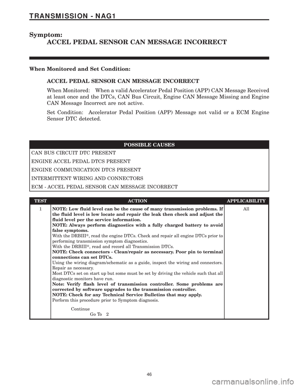
Symptom:
ACCEL PEDAL SENSOR CAN MESSAGE INCORRECT
When Monitored and Set Condition:
ACCEL PEDAL SENSOR CAN MESSAGE INCORRECT
When Monitored: When a valid Accelerator Pedal Position (APP) CAN Message Received
at least once and the DTCs, CAN Bus Circuit, Engine CAN Message Missing and Engine
CAN Message Incorrect are not active.
Set Condition: Accelerator Pedal Position (APP) Message not valid or a ECM Engine
Sensor DTC detected.
POSSIBLE CAUSES
CAN BUS CIRCUIT DTC PRESENT
ENGINE ACCEL PEDAL DTCS PRESENT
ENGINE COMMUNICATION DTCS PRESENT
INTERMITTENT WIRING AND CONNECTORS
ECM - ACCEL PEDAL SENSOR CAN MESSAGE INCORRECT
TEST ACTION APPLICABILITY
1NOTE: Low fluid level can be the cause of many transmission problems. If
the fluid level is low locate and repair the leak then check and adjust the
fluid level per the service information.
NOTE: Always perform diagnostics with a fully charged battery to avoid
false symptoms.
With the DRBIIIt, read the engine DTCs. Check and repair all engine DTCs prior to
performing transmission symptom diagnostics.
With the DRBIIIt, read and record all Transmission DTCs.
NOTE: Check connectors - Clean/repair as necessary. Poor pin to terminal
connections can set DTCs.
Using the wiring diagram/schematic as a guide, inspect the wiring and connectors.
Repair as necessary.
Most DTCs set on start up but some must be set by driving the vehicle such that all
diagnostic monitors have run.
Note: Verify flash level of transmission controller. Some problems are
corrected by software upgrades to the transmission controller.
NOTE: Check for any Technical Service Bulletins that may apply.
Perform this procedure prior to Symptom diagnosis.All
Continue
Go To 2
46
TRANSMISSION - NAG1
Page 2214 of 2305
TEST ACTION APPLICABILITY
1NOTE: Low fluid level can be the cause of many transmission problems. If
the fluid level is low locate and repair the leak then check and adjust the
fluid level per the service information.
NOTE: Always perform diagnostics with a fully charged battery to avoid
false symptoms.
With the DRBIIIt, read the engine DTCs. Check and repair all engine DTCs prior to
performing transmission symptom diagnostics.
With the DRBIIIt, read and record all Transmission DTCs.
NOTE: Check connectors - Clean/repair as necessary. Poor pin to terminal
connections can set DTCs.
Using the wiring diagram/schematic as a guide, inspect the wiring and connectors.
Repair as necessary.
Most DTCs set on start up but some must be set by driving the vehicle such that all
diagnostic monitors have run.
Note: Verify flash level of transmission controller. Some problems are
corrected by software upgrades to the transmission controller.
NOTE: Check for any Technical Service Bulletins that may apply.
Perform this procedure prior to Symptom diagnosis.All
Continue
Go To 2
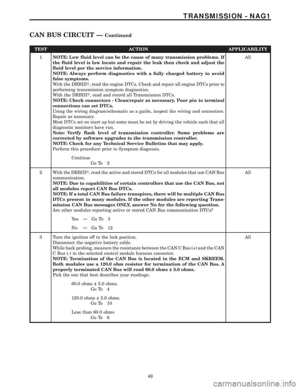
2 With the DRBIIIt, read the active and stored DTCs for all modules that use CAN Bus
communication.
NOTE: Due to capabilities of certain controllers that use the CAN Bus, not
all modules report CAN Bus DTCs.
NOTE: If a total CAN Bus failure transpires, there will be multiple CAN Bus
DTCs present in many modules. If the other modules are reporting Trans-
mission CAN Bus messages ONLY, answer No for the following question.
Are other modules reporting active or stored CAN Bus communication DTCs?All
Ye s!Go To 3
No!Go To 12
3 Turn the ignition off to the lock position.
Disconnect the negative battery cable.
While back probing, measure the resistance between the CAN C Bus (+) and the CAN
C Bus (-) in the selected control module harness connector.
NOTE: Termination of the CAN Bus is located in the ECM and SKREEM.
Both modules use a 120.0 ohm resistor for termination of the CAN Bus. A
properly terminated CAN Bus will read 60.0 ohms 5.0 ohms.
Pick the one that best describes your readings:All
60.0 ohms 5.0 ohms.
Go To 4
120.0 ohms 5.0 ohms.
Go To 10
Less than 60.0 ohms
Go To 8
49
TRANSMISSION - NAG1
CAN BUS CIRCUIT ÐContinued
Page 2215 of 2305
TEST ACTION APPLICABILITY
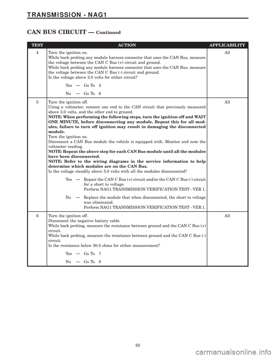
4 Turn the ignition on.
While back probing any module harness connector that uses the CAN Bus, measure
the voltage between the CAN C Bus (+) circuit and ground.
While back probing any module harness connector that uses the CAN Bus, measure
the voltage between the CAN C Bus (-) circuit and ground.
Is the voltage above 3.0 volts for either circuit?All
Ye s!Go To 5
No!Go To 6
5 Turn the ignition off.
Using a voltmeter, connect one end to the CAN circuit that previously measured
above 3.0 volts, and the other end to ground.
NOTE: When performing the following steps, turn the ignition off and WAIT
ONE MINUTE, before disconnecting any module. Repeat this for all mod-
ules, failure to turn off ignition may result in damaging the disconnected
module.
Turn the ignition on.
Disconnect a CAN Bus module the vehicle is equipped with. Monitor and note the
voltmeter reading.
NOTE: Repeat the above step for each CAN Bus module until all the modules
have been disconnected.
NOTE: Refer to the wiring diagrams in the service information to help
determine which modules are on the CAN Bus.
Is the voltage steadily above 3.0 volts with all the modules disconnected?All
Ye s!Repair the CAN C Bus (+) circuit and/or the CAN C Bus (-) circuit
for a short to voltage.
Perform NAG1 TRANSMISSION VERIFICATION TEST - VER 1.
No!Replace the module that when disconnected, the short to voltage
was eliminated.
Perform NAG1 TRANSMISSION VERIFICATION TEST - VER 1.
6 Turn the ignition off.
Disconnect the negative battery cable.
While back probing, measure the resistance between ground and the CAN C Bus (+)
circuit.
While back probing, measure the resistance between ground and the CAN C Bus (-)
circuit.
Is the resistance below 50.0 ohms for either measurement?All
Ye s!Go To 7
No!Go To 8
50
TRANSMISSION - NAG1
CAN BUS CIRCUIT ÐContinued
Page 2216 of 2305
TEST ACTION APPLICABILITY
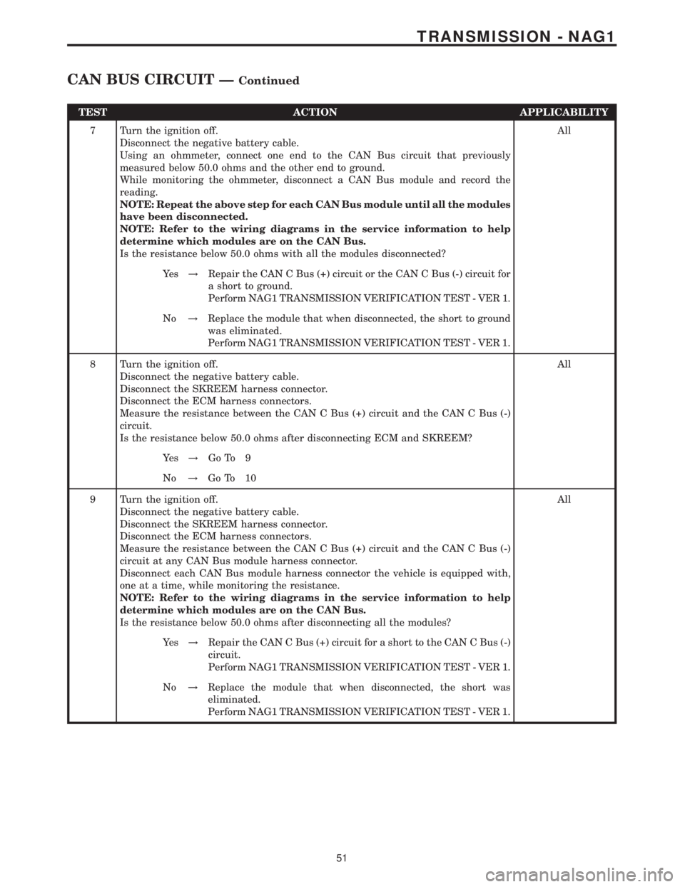
7 Turn the ignition off.
Disconnect the negative battery cable.
Using an ohmmeter, connect one end to the CAN Bus circuit that previously
measured below 50.0 ohms and the other end to ground.
While monitoring the ohmmeter, disconnect a CAN Bus module and record the
reading.
NOTE: Repeat the above step for each CAN Bus module until all the modules
have been disconnected.
NOTE: Refer to the wiring diagrams in the service information to help
determine which modules are on the CAN Bus.
Is the resistance below 50.0 ohms with all the modules disconnected?All
Ye s!Repair the CAN C Bus (+) circuit or the CAN C Bus (-) circuit for
a short to ground.
Perform NAG1 TRANSMISSION VERIFICATION TEST - VER 1.
No!Replace the module that when disconnected, the short to ground
was eliminated.
Perform NAG1 TRANSMISSION VERIFICATION TEST - VER 1.
8 Turn the ignition off.
Disconnect the negative battery cable.
Disconnect the SKREEM harness connector.
Disconnect the ECM harness connectors.
Measure the resistance between the CAN C Bus (+) circuit and the CAN C Bus (-)
circuit.
Is the resistance below 50.0 ohms after disconnecting ECM and SKREEM?All
Ye s!Go To 9
No!Go To 10
9 Turn the ignition off.
Disconnect the negative battery cable.
Disconnect the SKREEM harness connector.
Disconnect the ECM harness connectors.
Measure the resistance between the CAN C Bus (+) circuit and the CAN C Bus (-)
circuit at any CAN Bus module harness connector.
Disconnect each CAN Bus module harness connector the vehicle is equipped with,
one at a time, while monitoring the resistance.
NOTE: Refer to the wiring diagrams in the service information to help
determine which modules are on the CAN Bus.
Is the resistance below 50.0 ohms after disconnecting all the modules?All
Ye s!Repair the CAN C Bus (+) circuit for a short to the CAN C Bus (-)
circuit.
Perform NAG1 TRANSMISSION VERIFICATION TEST - VER 1.
No!Replace the module that when disconnected, the short was
eliminated.
Perform NAG1 TRANSMISSION VERIFICATION TEST - VER 1.
51
TRANSMISSION - NAG1
CAN BUS CIRCUIT ÐContinued
Page 2218 of 2305

Symptom:
CAN MESSAGE FROM ECM FROM SLA
When Monitored and Set Condition:
CAN MESSAGE FROM ECM FROM SLA
When Monitored:
Set Condition: CAN Bus message received from the Shift Lever Assembly are incorrect.
POSSIBLE CAUSES
CAN BUS CIRCUIT DTC PRESENT
SHIFT LEVER DTCS PRESENT
OPEN CAN BUS CIRCUITS AT SHIFT LEVER
SHIFT LEVER ASSEMBLY
TEST ACTION APPLICABILITY
1NOTE: Low fluid level can be the cause of many transmission problems. If
the fluid level is low locate and repair the leak then check and adjust the
fluid level per the service information.
NOTE: Always perform diagnostics with a fully charged battery to avoid
false symptoms.
With the DRBIIIt, read the engine DTCs. Check and repair all engine DTCs prior to
performing transmission symptom diagnostics.
With the DRBIIIt, read and record all Transmission DTCs.
NOTE: Check connectors - Clean/repair as necessary. Poor pin to terminal
connections can set DTCs.
Using the wiring diagram/schematic as a guide, inspect the wiring and connectors.
Repair as necessary.
Most DTCs set on start up but some must be set by driving the vehicle such that all
diagnostic monitors have run.
Note: Verify flash level of transmission controller. Some problems are
corrected by software upgrades to the transmission controller.
NOTE: Check for any Technical Service Bulletins that may apply.
Perform this procedure prior to Symptom diagnosis.All
Continue
Go To 2
2 Ignition on, engine not running.
With the DRBIIIt, read Transmission DTCs.
NOTE: If the DTC, CAN BUS CIRCUIT, is present, perform diagnostics on
that symptom first.
Is the DTC, CAN BUS CIRCUIT, present?All
Ye s!Refer to the Transmission category and perform the appropriate
symptom.
No!Go To 3
53
TRANSMISSION - NAG1
Page 2221 of 2305
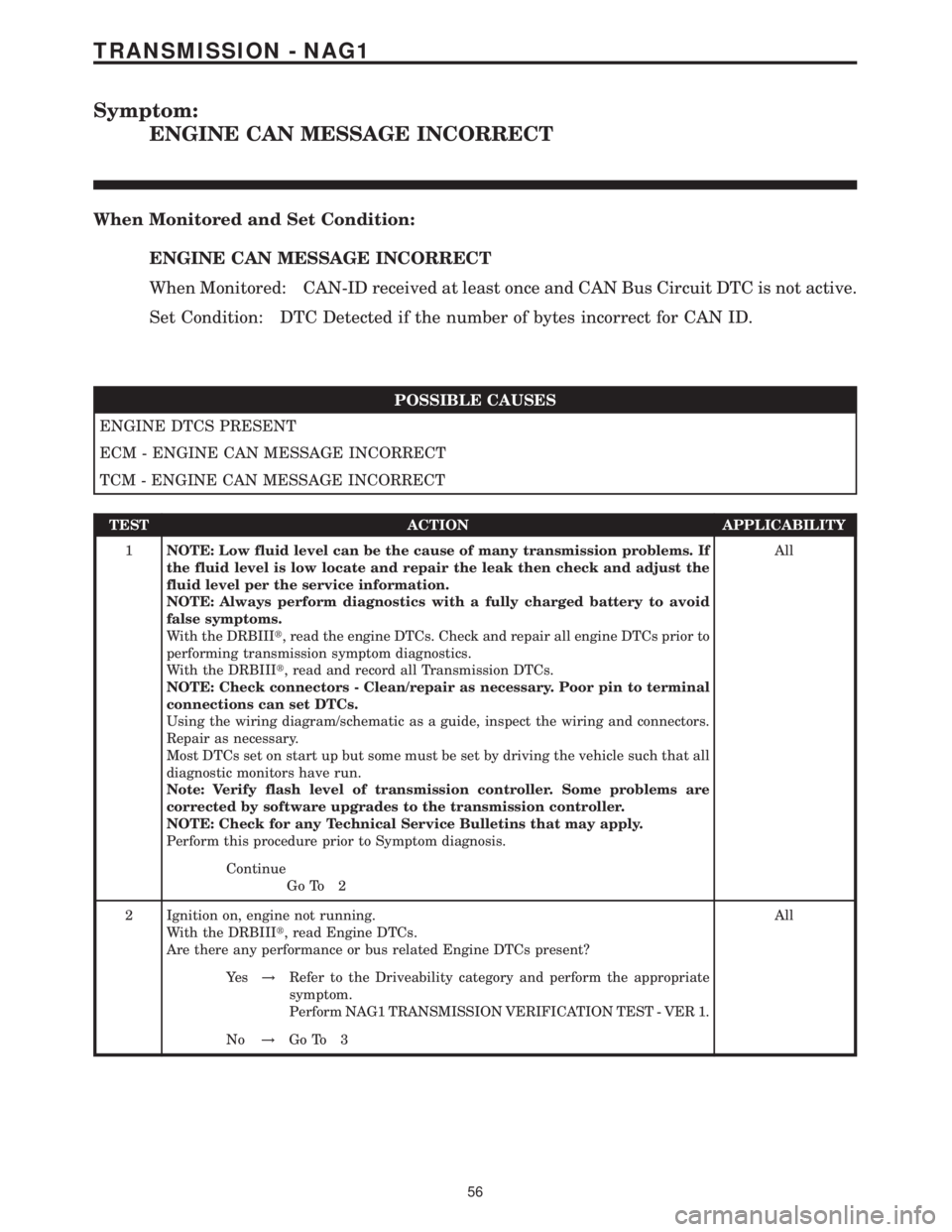
Symptom:
ENGINE CAN MESSAGE INCORRECT
When Monitored and Set Condition:
ENGINE CAN MESSAGE INCORRECT
When Monitored: CAN-ID received at least once and CAN Bus Circuit DTC is not active.
Set Condition: DTC Detected if the number of bytes incorrect for CAN ID.
POSSIBLE CAUSES
ENGINE DTCS PRESENT
ECM - ENGINE CAN MESSAGE INCORRECT
TCM - ENGINE CAN MESSAGE INCORRECT
TEST ACTION APPLICABILITY
1NOTE: Low fluid level can be the cause of many transmission problems. If
the fluid level is low locate and repair the leak then check and adjust the
fluid level per the service information.
NOTE: Always perform diagnostics with a fully charged battery to avoid
false symptoms.
With the DRBIIIt, read the engine DTCs. Check and repair all engine DTCs prior to
performing transmission symptom diagnostics.
With the DRBIIIt, read and record all Transmission DTCs.
NOTE: Check connectors - Clean/repair as necessary. Poor pin to terminal
connections can set DTCs.
Using the wiring diagram/schematic as a guide, inspect the wiring and connectors.
Repair as necessary.
Most DTCs set on start up but some must be set by driving the vehicle such that all
diagnostic monitors have run.
Note: Verify flash level of transmission controller. Some problems are
corrected by software upgrades to the transmission controller.
NOTE: Check for any Technical Service Bulletins that may apply.
Perform this procedure prior to Symptom diagnosis.All
Continue
Go To 2
2 Ignition on, engine not running.
With the DRBIIIt, read Engine DTCs.
Are there any performance or bus related Engine DTCs present?All
Ye s!Refer to the Driveability category and perform the appropriate
symptom.
Perform NAG1 TRANSMISSION VERIFICATION TEST - VER 1.
No!Go To 3
56
TRANSMISSION - NAG1
Page 2223 of 2305
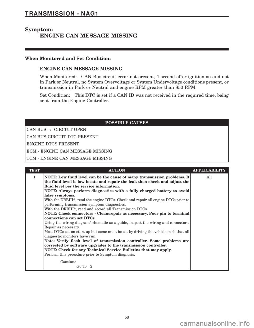
Symptom:
ENGINE CAN MESSAGE MISSING
When Monitored and Set Condition:
ENGINE CAN MESSAGE MISSING
When Monitored: CAN Bus circuit error not present, 1 second after ignition on and not
in Park or Neutral, no System Overvoltage or System Undervoltage conditions present, or
transmission in Park or Neutral and engine RPM greater than 850 RPM.
Set Condition: This DTC is set if a CAN ID was not received in the required time, being
sent from the Engine Controller.
POSSIBLE CAUSES
CAN BUS +/- CIRCUIT OPEN
CAN BUS CIRCUIT DTC PRESENT
ENGINE DTCS PRESENT
ECM - ENGINE CAN MESSAGE MISSING
TCM - ENGINE CAN MESSAGE MISSING
TEST ACTION APPLICABILITY
1NOTE: Low fluid level can be the cause of many transmission problems. If
the fluid level is low locate and repair the leak then check and adjust the
fluid level per the service information.
NOTE: Always perform diagnostics with a fully charged battery to avoid
false symptoms.
With the DRBIIIt, read the engine DTCs. Check and repair all engine DTCs prior to
performing transmission symptom diagnostics.
With the DRBIIIt, read and record all Transmission DTCs.
NOTE: Check connectors - Clean/repair as necessary. Poor pin to terminal
connections can set DTCs.
Using the wiring diagram/schematic as a guide, inspect the wiring and connectors.
Repair as necessary.
Most DTCs set on start up but some must be set by driving the vehicle such that all
diagnostic monitors have run.
Note: Verify flash level of transmission controller. Some problems are
corrected by software upgrades to the transmission controller.
NOTE: Check for any Technical Service Bulletins that may apply.
Perform this procedure prior to Symptom diagnosis.All
Continue
Go To 2
58
TRANSMISSION - NAG1
Page 2225 of 2305
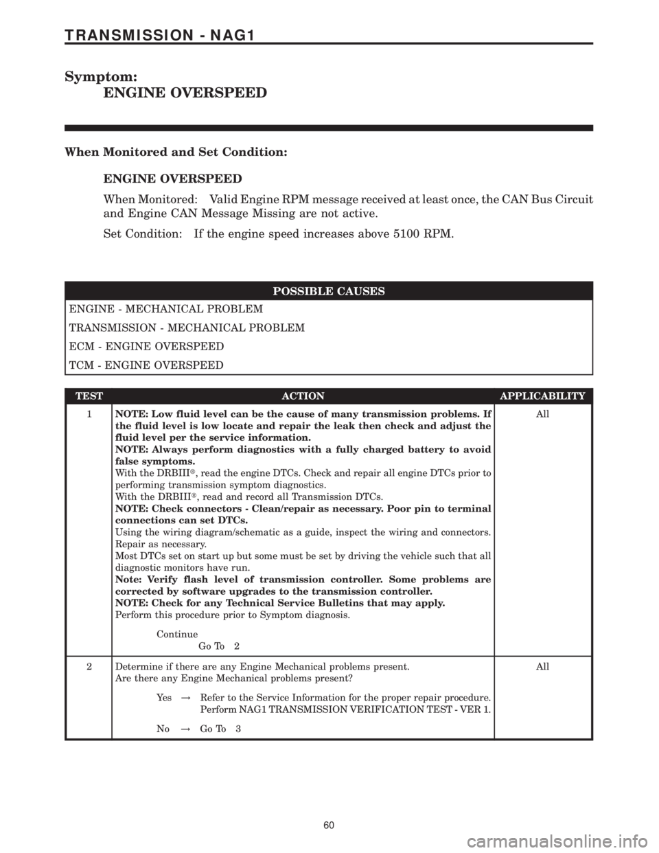
Symptom:
ENGINE OVERSPEED
When Monitored and Set Condition:
ENGINE OVERSPEED
When Monitored: Valid Engine RPM message received at least once, the CAN Bus Circuit
and Engine CAN Message Missing are not active.
Set Condition: If the engine speed increases above 5100 RPM.
POSSIBLE CAUSES
ENGINE - MECHANICAL PROBLEM
TRANSMISSION - MECHANICAL PROBLEM
ECM - ENGINE OVERSPEED
TCM - ENGINE OVERSPEED
TEST ACTION APPLICABILITY
1NOTE: Low fluid level can be the cause of many transmission problems. If
the fluid level is low locate and repair the leak then check and adjust the
fluid level per the service information.
NOTE: Always perform diagnostics with a fully charged battery to avoid
false symptoms.
With the DRBIIIt, read the engine DTCs. Check and repair all engine DTCs prior to
performing transmission symptom diagnostics.
With the DRBIIIt, read and record all Transmission DTCs.
NOTE: Check connectors - Clean/repair as necessary. Poor pin to terminal
connections can set DTCs.
Using the wiring diagram/schematic as a guide, inspect the wiring and connectors.
Repair as necessary.
Most DTCs set on start up but some must be set by driving the vehicle such that all
diagnostic monitors have run.
Note: Verify flash level of transmission controller. Some problems are
corrected by software upgrades to the transmission controller.
NOTE: Check for any Technical Service Bulletins that may apply.
Perform this procedure prior to Symptom diagnosis.All
Continue
Go To 2
2 Determine if there are any Engine Mechanical problems present.
Are there any Engine Mechanical problems present?All
Ye s!Refer to the Service Information for the proper repair procedure.
Perform NAG1 TRANSMISSION VERIFICATION TEST - VER 1.
No!Go To 3
60
TRANSMISSION - NAG1