2006 LAND ROVER FRELANDER 2 steering
[x] Cancel search: steeringPage 1886 of 3229
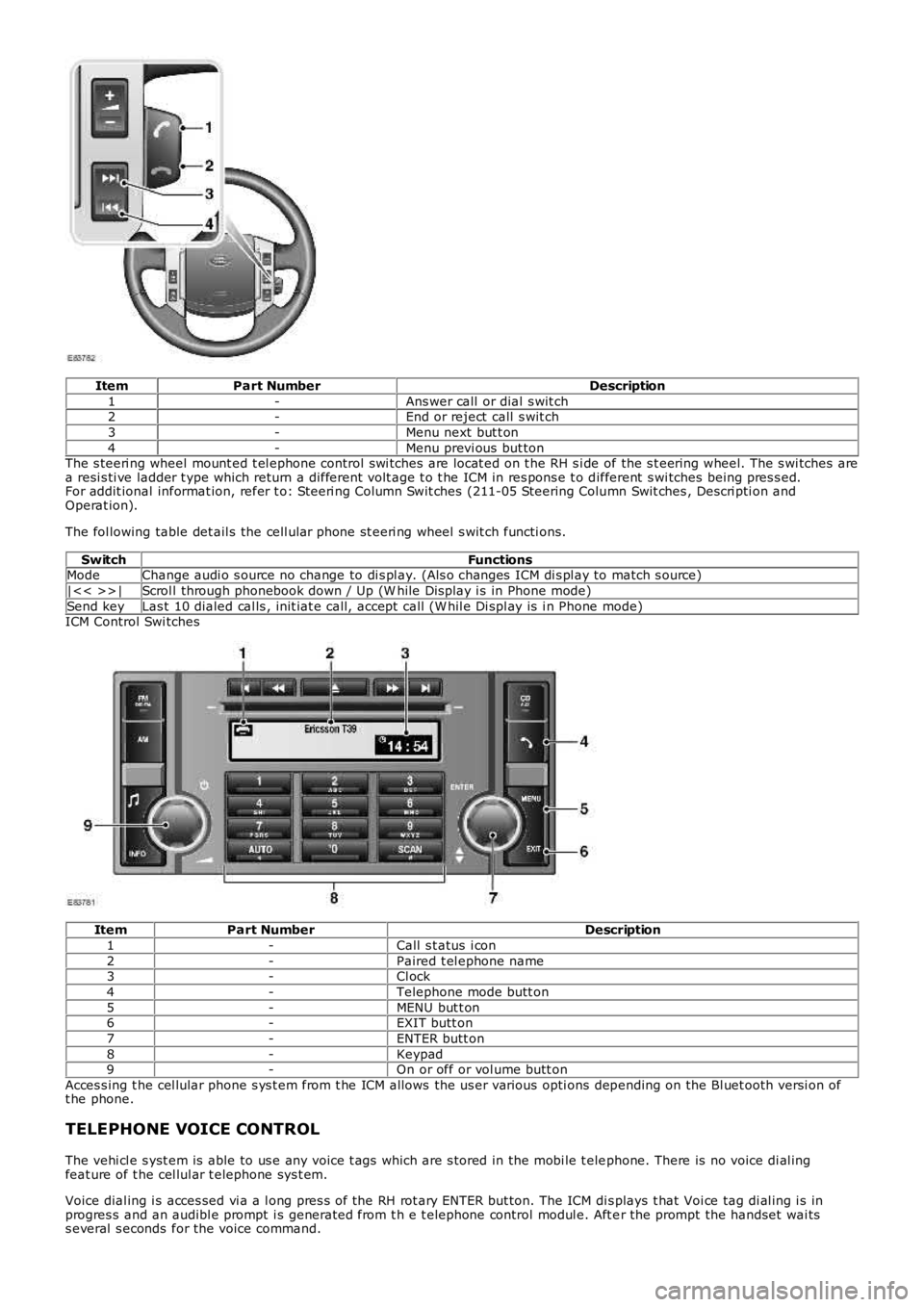
ItemPart NumberDescription
1-Ans wer call or dial s wit ch2-End or reject call s wit ch
3-Menu next but t on
4-Menu previ ous but tonThe s teeri ng wheel mount ed t el ephone control swi tches are locat ed on t he RH s i de of the s t eering wheel. The s wi tches area resi s ti ve ladder t ype which return a different volt age t o t he ICM in res pons e t o different s wi tches being pres s ed.For addit ional informat ion, refer t o: Steeri ng Column Swit ches (211-05 Steering Column Swit ches , Descri pti on andOperat ion).
The fol lowing table det ail s the cell ular phone st eeri ng wheel s wit ch functi ons.
SwitchFunctionsModeChange audi o s ource no change to di s pl ay. (Als o changes ICM di s pl ay to match s ource)
|<< >>|Scrol l through phonebook down / Up (W hile Dis play i s in Phone mode)
Send keyLas t 10 dialed cal ls , init iat e call, accept call (W hil e Di spl ay is i n Phone mode)ICM Control Swi tches
ItemPart NumberDescription
1-Call s t atus i con
2-Paired t el ephone name3-Cl ock
4-Telephone mode butt on
5-MENU but t on6-EXIT butt on
7-ENTER butt on
8-Keypad9-On or off or vol ume butt on
Acces s ing t he cel lular phone s ys t em from t he ICM allows the us er various opti ons depending on the Bl uet ooth versi on oft he phone.
TELEPHONE VOICE CONTROL
The vehi cl e s yst em is able to us e any voice t ags which are s tored in the mobi le t elephone. There is no voice di al ingfeat ure of t he cel lul ar t elephone sys t em.
Voice dial ing i s acces sed vi a a l ong pres s of the RH rot ary ENTER but ton. The ICM dis plays t hat Voi ce tag di al ing i s inprogres s and an audibl e prompt i s generated from t h e t elephone control modul e. Aft er the prompt the handset wai tss everal s econds for the voice command.
Page 1920 of 3229
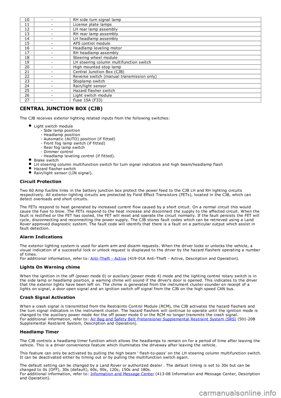
10-RH s i de turn s ignal lamp
11-Licens e pl ate lamps
12-LH rear l amp as s embl y13-RH rear lamp as s embly
14-LH headlamp as s embly
15-AFS cont rol module16-Headl amp l evel ing mot or
17-RH headlamp as s embly
18-Steering wheel modul e19-LH s t eering column mult ifunct ion s wit ch
20-High mount ed s top lamp
21-Central Junct ion Box (CJB)22-Revers e s wit ch (manual transmis si on only)
23-Stoplamp s wit ch
24-Rain/light s ensor25-Hazard flas her s wi tch
26-Light s wit ch modul e
27-Fuse 15A (F33)
CENTRAL JUNCTION BOX (CJB)
The CJB receives exteri or li ght ing relat ed inputs from t he fol lowing s wi tches:
Light s wit ch modul e- Side l amp pos it ion- Headlamp pos it ion- Automat ic (AUTO) posi ti on (if fi tt ed)- Front fog lamp swi tch (if fit ted)- Rear fog l amp s wit ch- Dimmer cont rol- Headlamp l evel ing control (if fit ted).Brake s wi tchLH s t eering column mult ifunct ion s wit ch for t urn si gnal i ndi cat ors and hi gh beam/headl amp flas hHazard flas her s wi tchRain/light s ensor (LIN si gnal ).
Circuit Protection
Two 60 Amp fus ibl e li nks in t he batt ery junct ion box protect the power feed to the CJB LH and RH li ght ing ci rcuit sres pect ively. All ext erior l ighti ng ci rcuit s are prot ect ed by Field Effect Trans is t ors (FETs ), l ocat ed in the CJB, which candetect overloads and s hort circuit s .
The FETs res pond to heat generated by increased current fl ow caus ed by a s hort ci rcuit . On a normal ci rcuit t his woul dcaus e t he fus e to bl ow. The FETs respond t o t he heat i ncrease and di s connect t he s uppl y t o t he affect ed ci rcuit . W hen t hefaul t is rect ified or t he FET has cool ed, t he FET wil l res et and operate t he circui t normall y. If t he faul t pers is ts the FET wi llcycle, di sconnect ing and reconnect ing t he power supply. The CJB s tores fault codes which can be ret rieved usi ng a LandRover approved diagnost ic sys tem. The fault code wil l identi fy t hat there is a fault on a part icular out put which as si s t infaul t det ect ion.
Alarm Indications
The exteri or li ght ing s ys tem is us ed for al arm arm and dis arm reques ts . W hen t he driver l ocks or unlocks the vehicle, avis ual i ndicat ion of a s uccess ful l ock or unlock reques t is di spl ayed t o t he dri ver by the hazard flas hers operat ing a numberof ti mes .For addit ional informat ion, refer t o: Anti -Theft - Act ive (419-01A Anti -Theft - Acti ve, Des cri pt ion and Operati on).
Lights On Warning chime
W hen t he i gni ti on in the off (power mode 0) or auxi liary (power mode 4) mode and the l ighti ng cont rol rotary swit ch is i nt he si de lamp or headlamp posi ti on, a warning chime wi ll s ound i f the driver's door is opened. This indicates t o t he dri vert hat t he exterior li ght s have been left on. The chime is generat ed from t he i ns t rument clus ter s ounder on receipt of ali ght s on s i gnal , a door open s ignal and an ignit ion swi tch off s ignal from t he CJB on the hi gh s peed CAN bus.
Crash Signal Activation
W hen a crash s ignal i s t rans mit ted from t he Rest rai nts Cont rol Modul e (RCM), t he CJB act ivat es the hazard flas hers andt he turn s ignal indicators in t he i ns t rument clus ter. The hazard fl ashers wil l continue to operate unt il t he ignit ion mode ischanged t o t he auxi liary power mode 4or the off power mode 0 or the RCM no longer trans mi ts the cras h si gnal .For addit ional informat ion, refer t o: Air Bag and Safet y Belt Pretens ioner Supplement al Res traint Syst em (SRS) (501-20BSuppl ement al Rest rai nt Sys tem, Des cri pti on and Operati on).
Headlamp Timer
The CJB cont rol s a headl amp t imer funct ion whi ch allows the headlamps t o remain on for a peri od of ti me after leaving t hevehi cl e. Thi s is a dri ver conveni ence feat ure which il lumi nat es t he dri veway after leaving t he vehicle.
This feat ure can onl y be acti vat ed by pulli ng t he high beam ' flas h-t o-pas s' on t he LH s t eering column mult ifunct ion s wi tch.It can be deacti vat ed eit her by ti ming out or by pull ing t he mul ti funct ion swi tch again.
The default s ett ing can be changed by a Land Rover or authorized deal er . The default t imi ng is s et t o 30s but can bechanged t o 0s (OFF), 30s (defaul t), 60s , 90s , 120s , 150s and 180s .For addit ional informat ion, refer t o: Informat ion and Mes s age Cent er (413-08 Informat ion and Mes s age Cent er, Des cript ionand Operat ion).
Page 1922 of 3229
The automat ic headlamp s ys tem uses a li ght s ens or and t he CJB, which are connect ed via the LIN bus t o cont rol t heheadl amp funct ional it y.
A l ight s ens or is incorporated in t he rai n/l ight s ens or located on the i nsi de of the windshi el d, bel ow t he rear view mirror.The wiper s yst em al s o uses the rain/l ight s ens or for aut omati c wiper operati on.For addit ional informat ion, refer t o: W i pers and W as hers (501-16 W ipers and W as hers , Des cri pti on and Operati on).
The li ght sens or meas ures the ambi ent l ight around t he vehi cl e i n a vert ical direct ion and als o the angular li ght l evel fromt he front of t he vehi cle. The rai n/li ght sens or us es vehicle s peed s ignals , wiper s wit ch posi ti on and the park posi ti on of thefront wipers to control the s ys tem.
The automat ic headlamp operat ion us es ambient l ight levels whi ch are moni tored by phot odiodes incorporat ed in t herai n/l ight sens or. The rain/l ight s ens or s ends a li ght s on/off request t o t he CJB on t he LIN bus , which res ponds bys wit chi ng on t he low beam headl amps, front s ide l amps, l icense plate lamps and rear t ail l amps. The aut omat ic headlampsare act ivated under the foll owing condi ti ons :
Twil ightDarknessRainTunnel sUnderground or mult is t ori ed car parks .
Operat ion of t he aut omat ic headl amps requires t he ignit ion t o be on (power mode 6), the l ighti ng cont rol rot ary swi tch t obe i n the 'AUTO' pos it ion and a li ght s on reques t s ignal from t he li ght sens or.
LEFT HAND STEERING COLUMN MULTIFUNCTION SWITCH
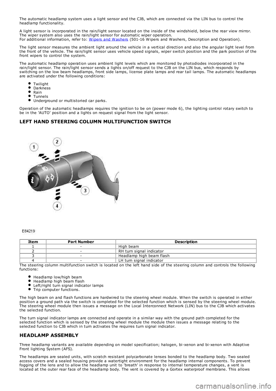
ItemPart NumberDescription
1-Hi gh beam
2-RH turn s ignal indicator3-Headlamp hi gh beam flas h
4-LH turn s ignal i ndi cat or
The s teeri ng column mul ti functi on s wit ch is l ocat ed on t he left hand s i de of the s t eering column and cont rols the foll owingfuncti ons :
Headl amp l ow/high beamHeadl amp hi gh beam fl ashLeft /right turn s ignal indicator l ampsTri p comput er functi ons .
The high beam on and fl ash funct ions are hardwi red t o t he s teeri ng wheel modul e. W hen the swi tch i s operat ed in ei therposi ti on a ground pat h via the s wi tch i s compl eted for the s elect ed functi on which is sens ed by t he s teeri ng wheel modul e.The s teeri ng wheel modul e t hen is s ues a mes sage on the Local Interconnect Net work (LIN) bus t o t he CJB which acti vat est he sel ect ed functi on.
The t urn s ignal indicator l amps are connect ed and operate in a si mi lar way wit h t he ground pat h compl eted for thes elect ed funct ion whi ch is s ensed by the s t eering wheel module t he module then i ss ues a mess age rel ati ng to thes elect ed funct ion t o CJB which i n t urn acti vat es t he requires turn s ignal indicator.
HEADLAMP ASSEMBLY
Three headlamp variants are available depending on model s peci fi cat ion; halogen, bi -xenon and bi-xenon wi th Adapt iveFront li ght ing Sys t em (AFS).
The headl amps are sealed uni ts , wit h s crat ch res is t ant polycarbonat e l ens es bonded to the headlamp body. Two s ealedacces s covers and a s ealed housi ng provide a waterti ght environment for the headlamp internal component s . To preventfogging of t he l ens and t o al low t he headlamp unit to 'breath' in res pons e t o i nternal t emperature changes , a vent i slocated at t he outer rear face of the headlamp body. The vent i s covered by a Gort ex wat erproof membrane. This al lows
Page 2485 of 3229
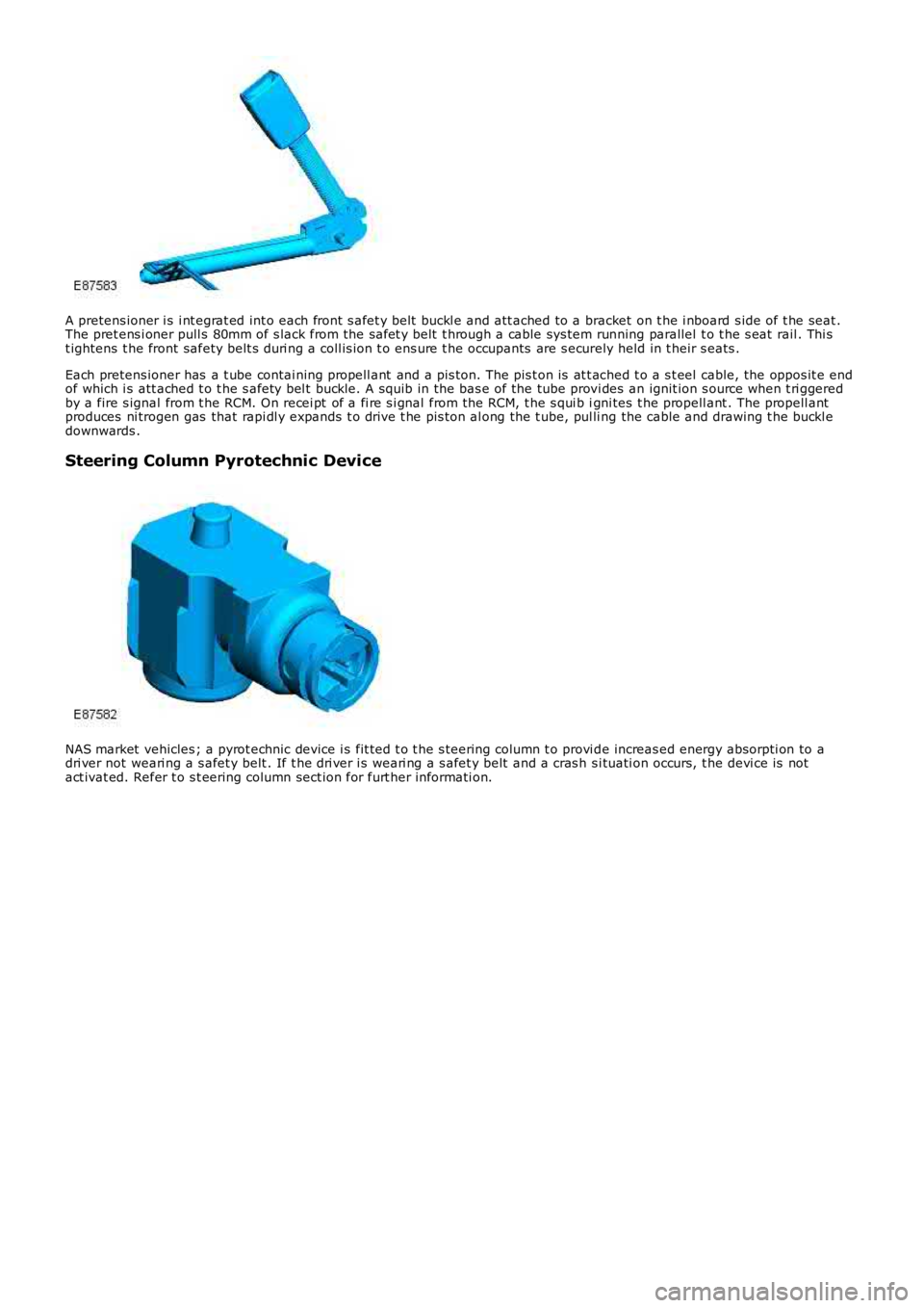
A pretens ioner i s i nt egrat ed int o each front s afet y belt buckl e and att ached to a bracket on t he i nboard s ide of t he seat .The pret ens i oner pull s 80mm of s lack from the safet y belt t hrough a cable sys tem running parallel t o t he s eat rail . Thi st ightens t he front safety belt s duri ng a coll is ion t o ens ure t he occupants are s ecurely held in t heir s eats .
Each pretens ioner has a t ube contai ning propell ant and a pis ton. The pis t on is at t ached t o a s t eel cable, the oppos it e endof which i s att ached t o t he s afety bel t buckle. A squib in the bas e of the tube provi des an ignit ion s ource when t ri ggeredby a fire s ignal from t he RCM. On recei pt of a fi re s i gnal from the RCM, t he s qui b igni tes t he propell ant . The propell antproduces ni trogen gas that rapi dl y expands t o dri ve t he pis ton al ong the t ube, pul ling the cable and drawing t he buckl edownwards .
Steering Column Pyrotechnic Device
NAS market vehicles ; a pyrot echnic device i s fit ted t o t he s teering column t o provi de increas ed energy absorpti on to adri ver not weari ng a s afet y belt . If t he dri ver i s weari ng a s afet y belt and a cras h s i tuati on occurs, t he devi ce is notact ivat ed. Refer t o s t eering column sect ion for furt her informati on.
Page 2697 of 3229
Publ is hed: 11-May-2011
Uni-Body, Subframe and Mounting System - Front SubframeRemoval and Installation
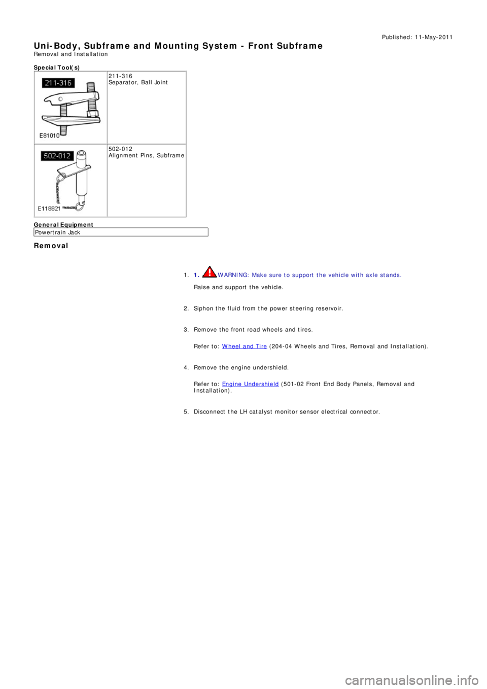
S p e c ia l T o o l( s )
211-316
Se p a ra t o r, B a l l Jo i nt
502-012
Alignment Pins, Subframe
General Equipment
P o we rt ra i n Ja ck
Removal
1. WARNING: Make sure to support the vehicle with axle stands.
Raise and support the vehicle. 1.
Siphon the fluid from the power steering reservoir. 2.
Remove the front road wheels and tires.
Refer to: W heel and Tire
(204-04 W heels and Tires , Removal and Ins t all at i on). 3.
Remove the engine undershield.
Refer to: Engine Undershield
(501-02 Front End Body Panel s, Removal and
Installation). 4.
Di sconnect t he LH cat al ys t monit or sens or elect ri cal connect or. 5.
Page 2699 of 3229
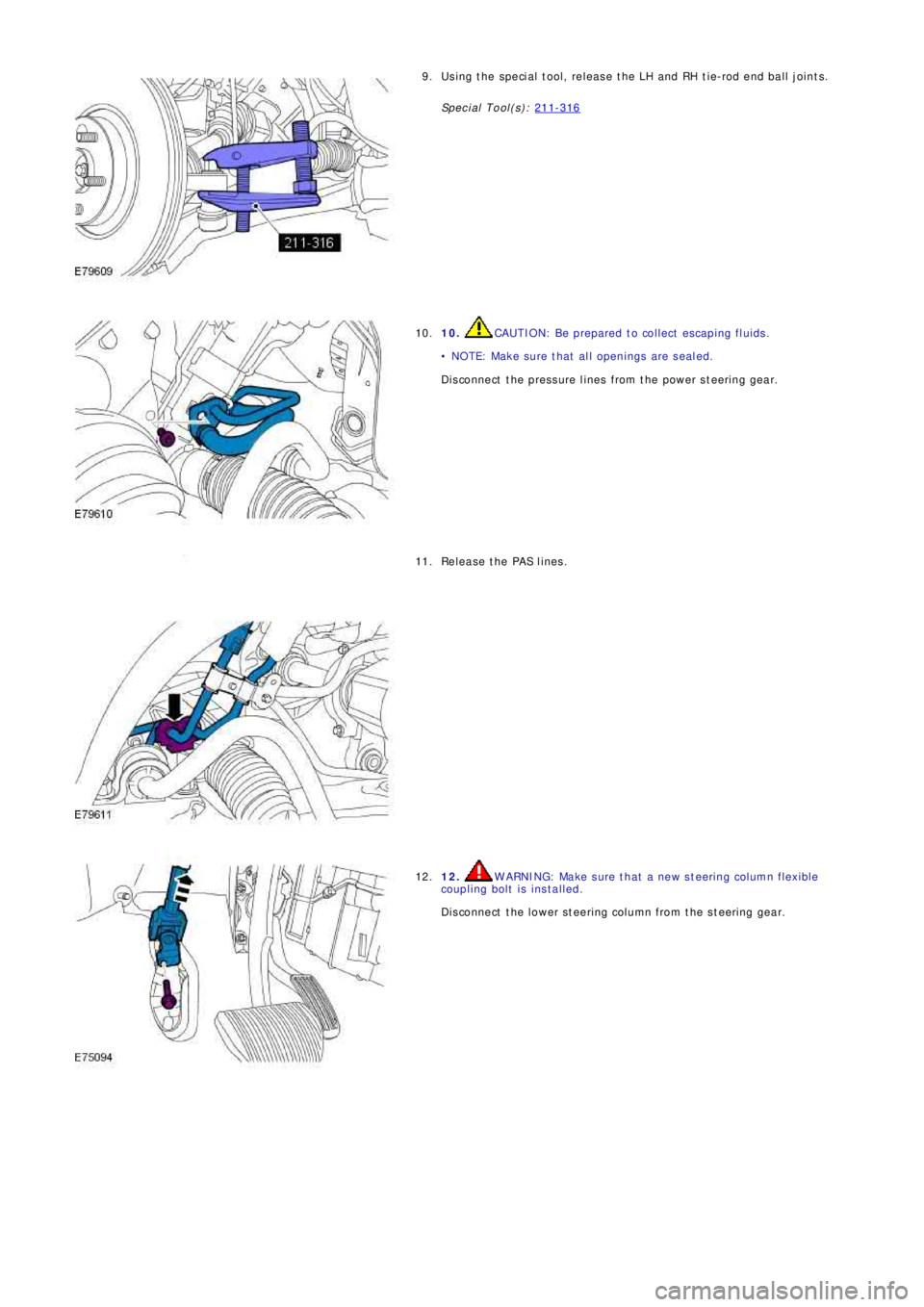
Using the special tool, release the LH and RH tie-rod end ball joints.
Special Tool(s): 211-3169.
10. CAUTION: Be prepared to collect escaping fluids.
• NOTE: Make sure that all openings are sealed.
Disconnect the pressure lines from the power steering gear. 10.
Release the PAS lines. 11.
12. WARNING: Make sure that a new steering column flexible
coupling bolt is installed.
Disconnect the lower steering column from the steering gear. 12.
Page 2702 of 3229
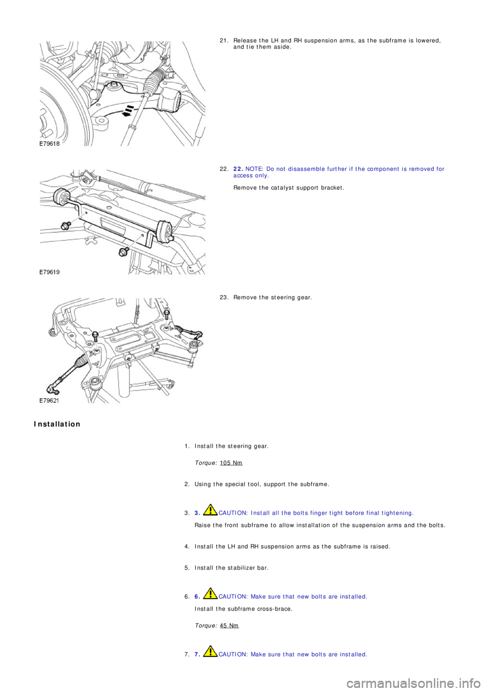
Release the LH and RH suspension arms, as the subframe is lowered,
and tie them aside. 21.
22. NOTE: Do not disassemble further if the component is removed for
access only.
Remove the catalyst support bracket. 22.
Remove the steering gear. 23.
Installation
Install the steering gear.
Torque: 105 Nm1.
Using the special tool, support the subframe. 2.
3.
CAUTION: Install all the bolts finger tight before final tightening.
Raise the front subframe to allow installation of the suspension arms and the bolts. 3.
Install the LH and RH suspension arms as the subframe is raised. 4.
Install the stabilizer bar. 5.
6.
CAUTION: Make sure that new bolts are installed.
Install the subframe cross-brace.
Torque: 45 Nm6.
7.
CAUTION: Make sure that new bolts are installed. 7.
Page 2703 of 3229
St a g e
1:
St a g e
2:
St a g e 1:
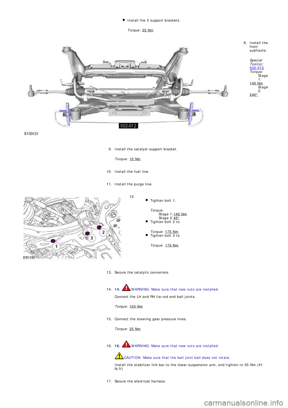
St a g e 2: Install the 2 support brackets.
Torque: 25 Nm
Install the
front
subframe.
Sp e c i a l
T ool (s ):
502-012
Torque:
140 Nm
240°
8.
Install the catalyst support bracket.
Torque: 10 Nm
9.
Install the fuel line. 10.
Install the purge line. 11.
Tighten bolt 1.
Torque:
140 Nm
45°Tighten bolt 2 to
Torque: 175 Nm
Tighten bolt 3 to
Torque: 175 Nm
12.
Secure the catalytic converters. 13.
14.
WARNING: Make sure that new nuts are installed.
Connect the LH and RH tie-rod end ball joints.
Torque: 105 Nm14.
Connect the steering gear pressure lines.
Torque: 25 Nm
15.
16.
WARNING: Make sure that new nuts are installed.
CAUTION: Make sure that the ball joint ball does not rotate.
Install the stabilizer link bar to the lower suspension arm, and tighten to 55 Nm (41
lb.ft) 16.
Secure the electrical harness. 17.