2006 LAND ROVER FRELANDER 2 steering
[x] Cancel search: steeringPage 593 of 3229
Publi s hed: 11-May-2011
Steering Column Switches - Ignition Switch
Removal and Inst all ati on
Removal
Make t he SRS s ys t em s afe.
Refer t o: Standard W orks hop Pract ices (100-00 General Informat ion,Des cript ion and Operat ion).
1.
Remove t he dri ver l ower ai r bag modul e.
Refer t o: Dri ver Lower Air Bag Module (501-20B SupplementalRes traint Sys t em, Removal and Inst all at ion).
2.
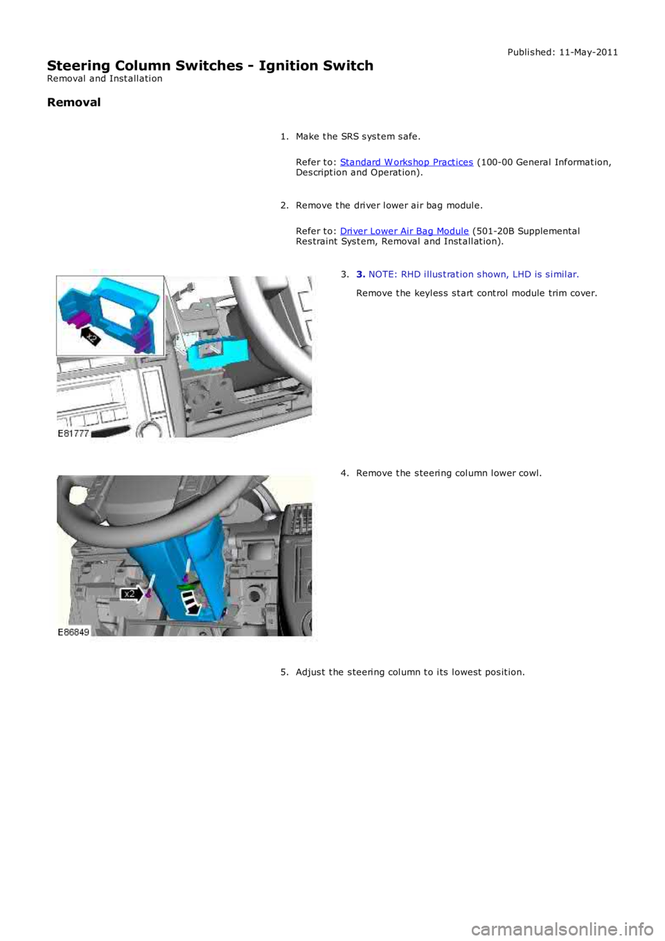
3. NOTE: RHD i llus t rat ion s hown, LHD is s i mil ar.
Remove t he keyl es s s t art cont rol module trim cover.
3.
Remove t he s teeri ng col umn l ower cowl.4.
Adjus t t he s teeri ng col umn t o i ts l owest pos it ion.5.
Page 596 of 3229
Publi s hed: 11-May-2011
Steering Column Switches - Steering Column Lock Module
Removal and Inst all ati on
Removal
• NOTE: On vehicles bui lt from VIN 091770 t he s teeri ng col umn l ock modul e may be a non-functi onal component .
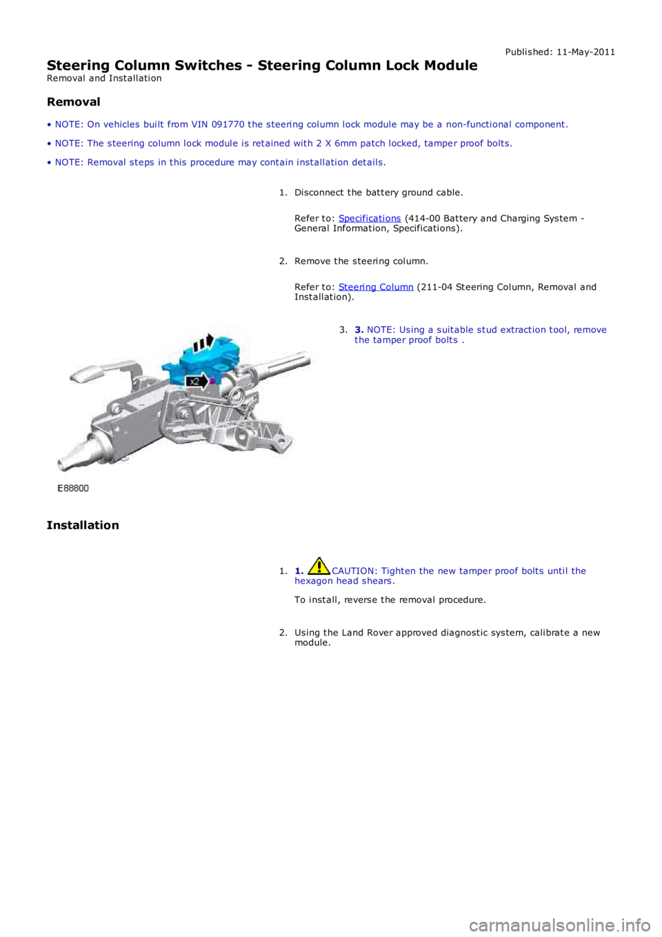
• NOTE: The s teering column l ock modul e i s ret ained wit h 2 X 6mm patch l ocked, tamper proof bolt s.
• NOTE: Removal s t eps in t his procedure may cont ain i nst all ati on det ail s.
Di sconnect t he bat t ery ground cable.
Refer t o: Specificati ons (414-00 Bat tery and Charging Sys tem -General Informat ion, Specificati ons).
1.
Remove t he s teeri ng col umn.
Refer t o: Steeri ng Column (211-04 St eering Col umn, Removal andInst all at ion).
2.
3. NOTE: Us ing a s uit able s t ud extract ion t ool, removet he tamper proof bolt s .3.
Installation
1. CAUTION: Tight en the new tamper proof bolt s unti l thehexagon head s hears .
To i nst all , revers e t he removal procedure.
1.
Us ing t he Land Rover approved diagnost ic sys tem, cali brat e a newmodule.2.
Page 1078 of 3229
informat ion read by the manufact urer approved diagnos t ic s ys tem).
• NOTE: W hen performing volt age or res is t ance t est s , always use a digi tal mult imeter (DMM) accurat e t o 3 decimal places,and wit h an up-to-dat e cali brati on cert ificat e. W hen t est ing res is tance, al ways take t he res i st ance of t he DMM leads int oaccount.
• NOTE: Check and recti fy bas ic faul ts before beginni ng diagnos t ic rout ines i nvol vi ng pinpoint t es t s.
• NOTE: If DTCs are recorded and, aft er performi ng the pi npoi nt tes ts , t he fault i s not pres ent , an i nt ermit tent concernmay be t he cause. Always check for loos e connecti ons and corroded t ermi nal s.
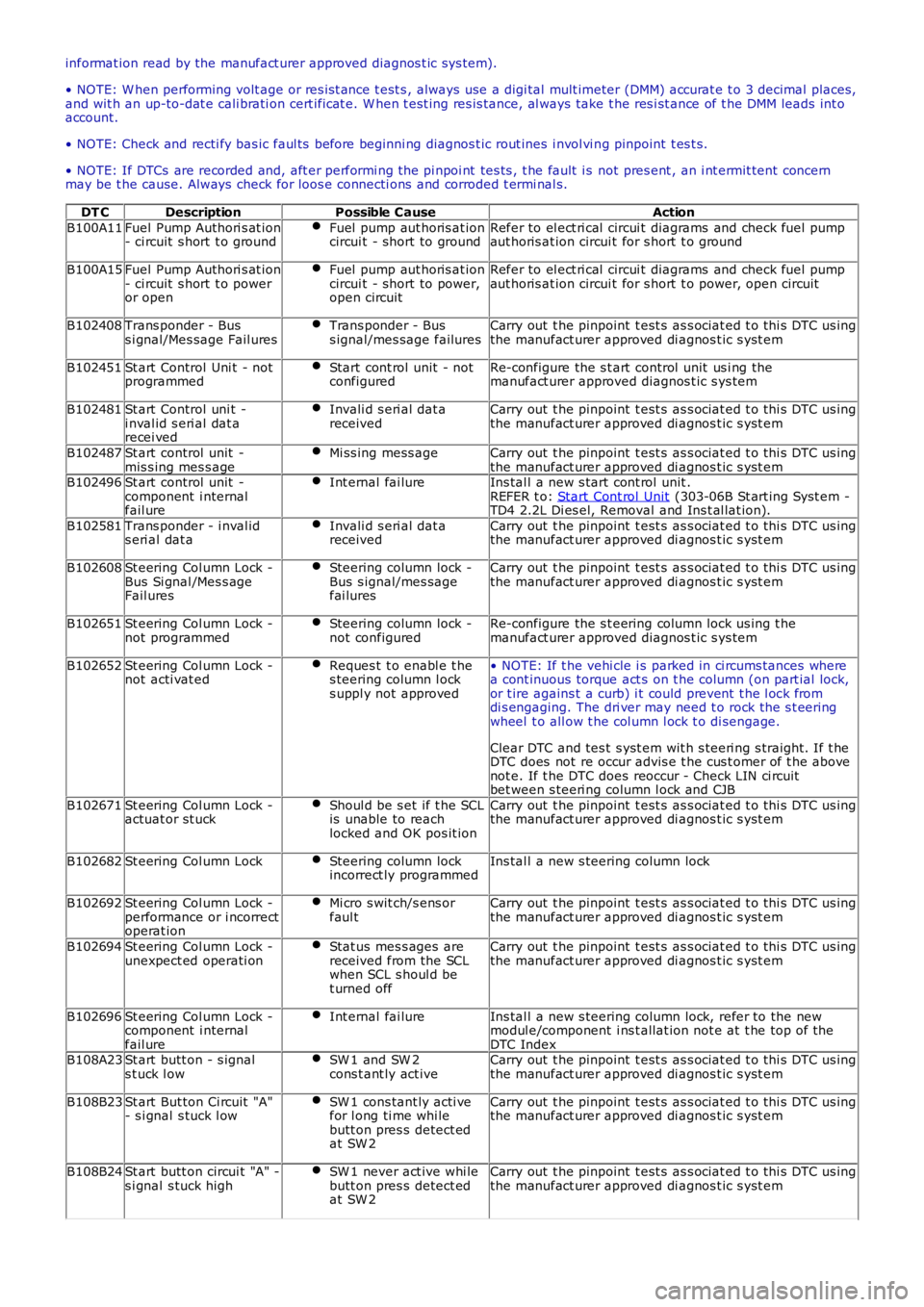
DT CDescriptionPossible CauseAction
B100A11Fuel Pump Authori s at ion- ci rcuit s hort t o groundFuel pump aut horis at ioncircui t - short to groundRefer to el ect ri cal circui t diagrams and check fuel pumpaut horis at ion circui t for s hort t o ground
B100A15Fuel Pump Authori s at ion- ci rcuit s hort t o poweror open
Fuel pump aut horis at ioncircui t - short to power,open circuit
Refer to el ect ri cal circui t diagrams and check fuel pumpaut horis at ion circui t for s hort t o power, open circuit
B102408Trans ponder - Buss i gnal/Mes sage Fail uresTrans ponder - Buss ignal/mes sage failuresCarry out t he pinpoint t est s as s ociat ed t o t hi s DTC us ingthe manufact urer approved di agnos t ic s yst em
B102451St art Control Uni t - notprogrammedStart cont rol unit - notconfiguredRe-configure the s t art control unit us i ng themanufact urer approved diagnos t ic s ys tem
B102481St art Control uni t -i nval id s eri al dat arecei ved
Invali d s eri al dat areceivedCarry out t he pinpoint t est s as s ociat ed t o t hi s DTC us ingthe manufact urer approved di agnos t ic s yst em
B102487St art control unit -mis s ing mes s ageMi ss ing mess ageCarry out t he pinpoint t est s as s ociat ed t o t hi s DTC us ingthe manufact urer approved di agnos t ic s yst emB102496St art control unit -component i nternalfail ure
Int ernal fai lureIns tal l a new s tart cont rol unit .REFER t o: Start Cont rol Unit (303-06B St art ing Syst em -TD4 2.2L Di es el, Removal and Ins t al lat ion).
B102581Trans ponder - i nval ids eri al dat aInvali d s eri al dat areceivedCarry out t he pinpoint t est s as s ociat ed t o t hi s DTC us ingthe manufact urer approved di agnos t ic s yst em
B102608St eering Col umn Lock -Bus Si gnal /Mes s ageFail ures
Steering column lock -Bus s ignal/mes sagefai lures
Carry out t he pinpoint t est s as s ociat ed t o t hi s DTC us ingthe manufact urer approved di agnos t ic s yst em
B102651St eering Col umn Lock -not programmedSteering column lock -not configuredRe-configure the s t eering column lock us ing t hemanufact urer approved diagnos t ic s ys tem
B102652St eering Col umn Lock -not acti vat edReques t t o enabl e t hes teering column l ocks uppl y not approved
• NOTE: If t he vehi cle i s parked in ci rcums tances wherea cont inuous torque act s on t he column (on part ial lock,or t ire agains t a curb) i t could prevent t he l ock fromdi s engaging. The dri ver may need t o rock the s t eeringwheel t o all ow t he col umn l ock t o di sengage.
Clear DTC and tes t s yst em wit h s teeri ng s traight. If t heDTC does not re occur advis e t he cus t omer of t he abovenot e. If t he DTC does reoccur - Check LIN ci rcuitbet ween s teeri ng column l ock and CJB
B102671St eering Col umn Lock -actuat or st uckShoul d be s et if t he SCLis unable to reachlocked and OK pos it ion
Carry out t he pinpoint t est s as s ociat ed t o t hi s DTC us ingthe manufact urer approved di agnos t ic s yst em
B102682St eering Col umn LockSteering column lockincorrect ly programmedIns tal l a new s teering column lock
B102692St eering Col umn Lock -performance or i ncorrectoperat ion
Mi cro s wit ch/s ens orfaul tCarry out t he pinpoint t est s as s ociat ed t o t hi s DTC us ingthe manufact urer approved di agnos t ic s yst em
B102694St eering Col umn Lock -unexpect ed operati onStat us mes s ages arereceived from the SCLwhen SCL s houl d bet urned off
Carry out t he pinpoint t est s as s ociat ed t o t hi s DTC us ingthe manufact urer approved di agnos t ic s yst em
B102696St eering Col umn Lock -component i nternalfail ure
Int ernal fai lureIns tal l a new s teering column lock, refer to the newmodul e/component i ns t allat ion not e at t he top of t heDTC IndexB108A23St art butt on - s ignals t uck l owSW 1 and SW 2cons t ant ly act iveCarry out t he pinpoint t est s as s ociat ed t o t hi s DTC us ingthe manufact urer approved di agnos t ic s yst em
B108B23St art But ton Ci rcuit "A"- s i gnal s tuck l owSW 1 cons tant ly acti vefor l ong ti me whi lebutt on pres s detect edat SW 2
Carry out t he pinpoint t est s as s ociat ed t o t hi s DTC us ingthe manufact urer approved di agnos t ic s yst em
B108B24St art butt on circui t "A" -s i gnal s tuck highSW 1 never act ive whi lebutt on pres s detect edat SW 2
Carry out t he pinpoint t est s as s ociat ed t o t hi s DTC us ingthe manufact urer approved di agnos t ic s yst em
Page 1293 of 3229
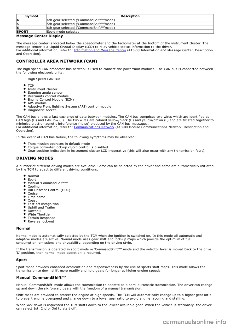
SymbolDescription
44th gear s elected ('CommandShift™ 'mode)
55th gear s elected ('CommandShift™ 'mode)66th gear s elected ('CommandShift™ 'mode)
SPORTSport mode s elected
Message Center Display
The mes s age center i s located bel ow t he speedometer and t he tachometer at t he bot t om of t he ins trument cl ust er. Themes s age center i s a Liqui d Crys tal Di spl ay (LCD) t o rel ay vehi cl e s tat us informat ion t o t he dri ver.For addit ional informat ion, refer t o: Informat ion and Mes s age Cent er (413-08 Informat ion and Mes s age Cent er, Des cript ionand Operat ion).
CONTROLLER AREA NETWORK (CAN)
The high s peed CAN broadcast bus net work i s us ed to connect t he powert rai n modules . The CAN bus is connect ed betweent he foll owing el ect ronic uni ts :
High Speed CAN Bus
TCMIns t rument clus terSteering angle s ens orRest rai nts control modul eEngi ne Control Module (ECM)ABS moduleAdapt ive Front l ight ing Syst em (AFS) cont rol moduleDiagnost ic socket .
The CAN bus all ows a fast exchange of dat a between modules . The CAN bus compri ses two wires which are identi fied asCAN hi gh (H) and CAN low (L). The t wo wires are colored yel low/bl ack (H) and yell ow/brown (L) and are twi s ted t oget her tomi ni mi se el ect romagneti c int erference (nois e) produced by the CAN bus mes sages .For addit ional informat ion, refer t o: Communicati ons Net work (418-00 Modul e Communicati ons Net work, Des cript ion andOperat ion).
In the event of CAN bus fai lure, t he fol lowi ng s ympt oms may be obs erved:
Trans mis s ion operat es in default modeTorque converter lock-up clut ch cont rol is dis abl edGear pos it ion indicati on in ins trument cl us t er LCD inoperati ve (t his will al so occur wit h any t rans mis s ion faul t).
DRIVING MODES
A number of different dri ving modes are avai lable. Some can be s elected by the driver and some are aut omati cal ly i nit iatedby t he TCM t o adapt t o di fferent drivi ng condit ions .
NormalSportManual 'CommandShift ™'CoolingHil l Descent Cont rol (HDC)Crui seLimp homeCoastFast off recogni ti onUphill and TrailerDownhillW i de Throt tl eTerrai n Res pons eRevers e lock-out
Normal
Normal mode is automat icall y s elect ed by t he TCM when t he i gni ti on is swi tched on. In this mode all automat ic andadapt ive modes are acti ve. Normal mode uses gear s hi ft and l ock-up maps which provi de the opt imum of fuelcons umpt ion, emis s ions and dri veabil it y, depending on t he dri ving s tyl e.
If the t rans mis s ion is operat ed in sport mode or 'CommandShi ft ™' mode and t he s elector lever is moved back t o t he drive'D' pos it ion, then normal mode operat ion is resumed.
Sport
Sport mode provi des enhanced accelerat ion and respons ivenes s by t he us e of s ports shi ft maps . This mode al lows t het ransmis s ion t o down s hift more readil y and hol d gears for longer at hi gher engine speeds .
Manual 'CommandShift™'
Manual 'CommandShift ' mode al lows t he t rans mis s ion t o operat e as a semi -aut omati c trans mi s si on. The driver can changeup and down t he s ix forward gears wi th the freedom of a manual t rans mis s ion.
Shift maps are provi ded to protect t he engi ne at high s peeds . The TCM wi ll automat icall y change up t o a higher gear rat iot o prevent engine overspeed and change down to a lower gear rati o t o avoi d engine l aboring and s t al li ng.
W hen ki ck-down is reques ted the TCM shi ft s down t o t he lowes t avai lable gear. W hen the vehicl e is st ati onary, t he drivercan s el ect 1s t , 2nd or 3rd t o s tart off.
Page 1776 of 3229
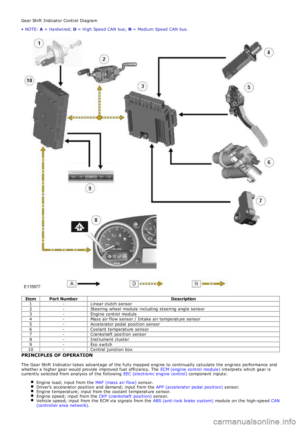
Gear Shi ft Indicat or Cont rol Di agram
• NOTE: A = Hardwi red; D = Hi gh Speed CAN bus ; N = Medium Speed CAN bus.
ItemPart NumberDescription1-Linear cl utch s ensor
2-Steering wheel modul e i ncludi ng st eeri ng angl e s ens or
3-Engi ne cont rol module4-Mas s air flow s ens or / Int ake ai r temperat ure sens or
5-Accelerator pedal pos it ion s ensor
6-Coolant temperat ure sens or7-Cranks haft pos i ti on s ens or
8-Ins t rument clus ter
9-Eco s wit ch10-Central junct ion box
PRINCIPLES OF OPERATION
The Gear Shi ft Indicat or takes advant age of the full y mapped engi ne to cont inually cal culat e t he engi nes performance andwhether a hi gher gear woul d provide improved fuel effi ci ency. The ECM (engi ne cont rol module) int erpret s whi ch gear iscurrent ly s elected from analys is of t he fol lowing EEC (elect ronic engine control) component i nput s:
Engi ne load; input from the MAF (mas s ai r flow) s ens or.Dri ver’s accelerat or pos it ion and demand; input from the APP (accelerator pedal pos it ion) s ens or.Engi ne t emperature; input from t he cool ant t emperat ure s ensor.Engi ne s peed; i nput from the CKP (cranks haft posi ti on) s ens or.Vehicle s peed; input from t he ECM via si gnal s from the ABS (anti -l ock brake s ys t em) module on t he high-speed CAN(controll er area network).
Page 1868 of 3229
Publi s hed: 11-May-2011
Information and Entertainment System - Audio System
Des cript ion and Operat ion
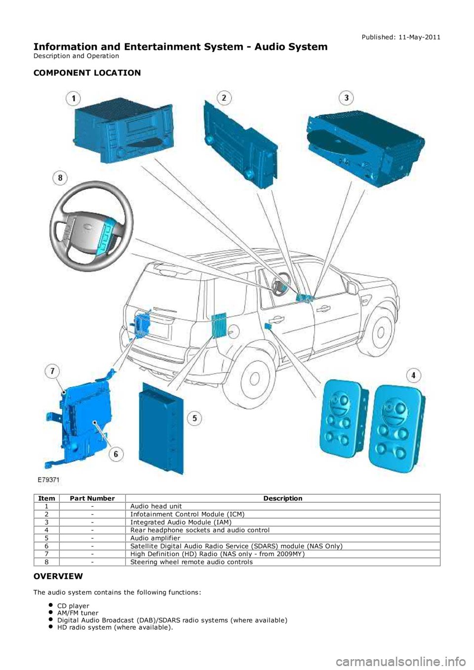
COMPONENT LOCATION
ItemPart NumberDescription1-Audio head unit
2-Infotai nment Cont rol Modul e (ICM)
3-Int egrat ed Audi o Module (IAM)4-Rear headphone socket s and audio control
5-Audio ampl ifier
6-Satell it e Di gi tal Audio Radi o Service (SDARS) modul e (NAS Only)7-High Defini ti on (HD) Radio (NAS onl y - from 2009MY )
8-Steering wheel remot e audi o control s
OVERVIEW
The audi o s yst em cont ai ns the foll owing funct ions :
CD pl ayerAM/FM tunerDigi tal Audio Broadcast (DAB)/SDARS radi o s yst ems (where avail abl e)HD radio s ys tem (where avai lable).
Page 1872 of 3229
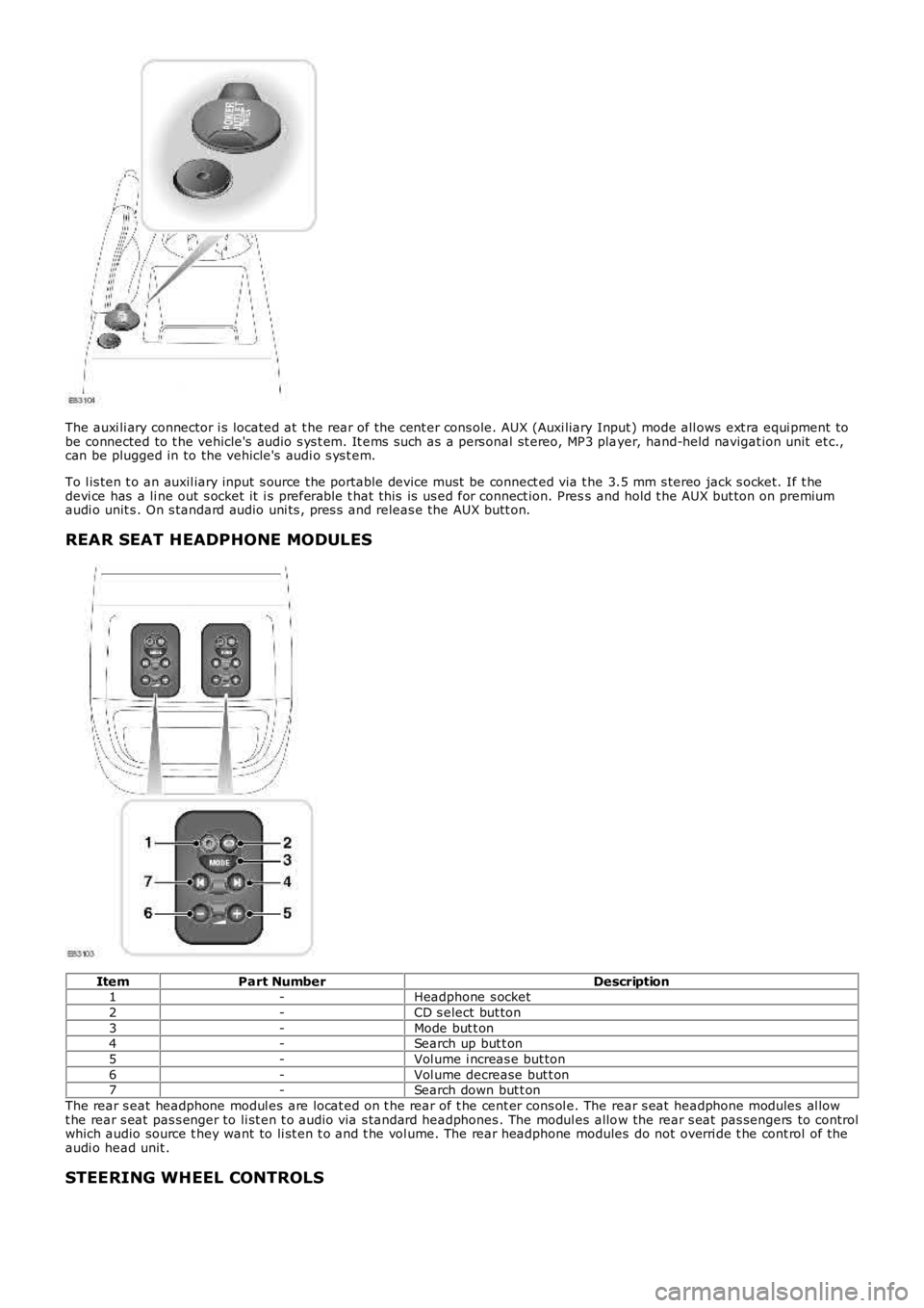
The auxi li ary connector i s located at t he rear of t he cent er cons ole. AUX (Auxi liary Input ) mode all ows ext ra equi pment tobe connected to t he vehicle's audio s ys t em. It ems s uch as a pers onal st ereo, MP3 player, hand-held navigat ion unit et c.,can be plugged in to the vehicle's audi o s ys t em.
To l is ten t o an auxil iary input s ource the portable device must be connect ed via t he 3.5 mm s tereo jack s ocket. If t hedevi ce has a li ne out s ocket it i s preferable t hat this is us ed for connect ion. Press and hold t he AUX but ton on premiumaudi o unit s . On s tandard audio uni ts , pres s and releas e the AUX butt on.
REAR SEAT HEADPHONE MODULES
ItemPart NumberDescription1-Headphone s ocket
2-CD s elect but ton
3-Mode but t on4-Search up but t on
5-Vol ume i ncreas e but ton
6-Vol ume decrease but t on7-Search down but t on
The rear s eat headphone modul es are locat ed on t he rear of t he cent er cons ol e. The rear s eat headphone modules al lowt he rear s eat pas s enger to li st en t o audio via s tandard headphones . The modul es allow the rear s eat pas sengers to controlwhich audio source t hey want to li st en t o and t he vol ume. The rear headphone modules do not overri de t he cont rol of theaudi o head unit .
STEERING WHEEL CONTROLS
Page 1873 of 3229
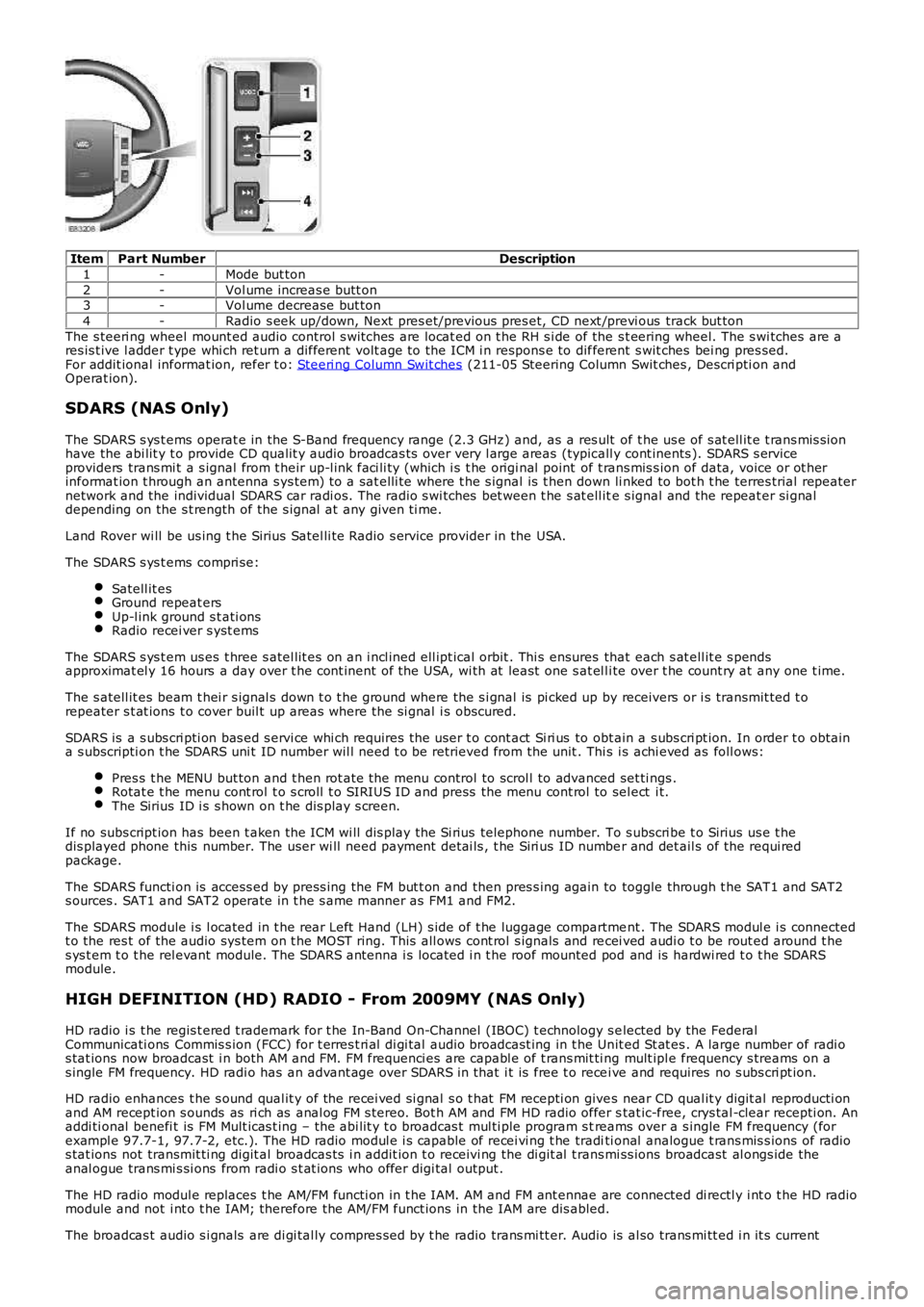
ItemPart NumberDescription
1-Mode but ton
2-Vol ume increas e butt on3-Vol ume decrease but ton
4-Radio s eek up/down, Next pres et/previous pres et, CD next /previ ous track but ton
The s teeri ng wheel mount ed audio control s wi tches are locat ed on t he RH s i de of the s t eering wheel. The s wi tches are ares is t ive l adder t ype whi ch ret urn a different volt age to the ICM i n respons e to different s wit ches bei ng pres sed.For addit ional informat ion, refer t o: Steeri ng Column Swit ches (211-05 Steering Column Swit ches , Descri pti on andOperat ion).
SDARS (NAS Only)
The SDARS s ys t ems operat e in the S-Band frequency range (2.3 GHz) and, as a res ult of t he us e of s at ell it e t rans mis s ionhave the abi lit y t o provide CD qualit y audio broadcas ts over very l arge areas (typicall y cont inents ). SDARS s erviceproviders trans mi t a s ignal from t heir up-l ink faci li ty (which i s t he origi nal point of t rans mis s ion of data, voice or ot herinformat ion t hrough an antenna s ys tem) t o a sat elli te where t he s ignal is t hen down li nked to bot h t he terres trial repeaternetwork and the individual SDARS car radi os. The radio s wi tches bet ween t he s at ell ite s ignal and the repeat er si gnaldepending on the s t rength of the s ignal at any given ti me.
Land Rover wi ll be us ing t he Sirius Satel li te Radio s ervice provider in the USA.
The SDARS s ys t ems compri se:
Satell it esGround repeat ersUp-l ink ground s t ati onsRadio recei ver s yst ems
The SDARS s ys t em us es t hree s atel lit es on an i ncl ined ell ipt ical orbit . Thi s ensures that each s at ell it e s pendsapproximat el y 16 hours a day over t he cont inent of the USA, wi th at least one s at el li te over t he count ry at any one t ime.
The s atell it es beam t hei r s ignal s down t o t he ground where the s i gnal is pi cked up by receivers or i s transmit ted t orepeater s t at ions t o cover buil t up areas where the si gnal i s obscured.
SDARS is a s ubs cri pti on bas ed s ervi ce whi ch requires the us er t o cont act Si ri us to obt ain a s ubs cri pt ion. In order t o obtaina s ubscripti on t he SDARS uni t ID number wil l need t o be retrieved from the unit . This i s achi eved as foll ows:
Pres s t he MENU but ton and t hen rot ate the menu control to scrol l to advanced set ti ngs .Rotat e t he menu cont rol t o s croll t o SIRIUS ID and press the menu cont rol to sel ect i t.The Sirius ID i s s hown on t he dis play s creen.
If no subs cript ion has been t aken the ICM wi ll dis play the Si rius telephone number. To s ubscri be t o Sirius us e t hedis played phone this number. The user wi ll need payment det ai ls , t he Siri us ID number and det ail s of the requi redpackage.
The SDARS functi on is access ed by press ing the FM but t on and then pres s ing again to toggle through t he SAT1 and SAT2s ources . SAT1 and SAT2 operate in t he s ame manner as FM1 and FM2.
The SDARS module i s l ocated in t he rear Left Hand (LH) s ide of t he luggage compartment . The SDARS modul e i s connectedt o the res t of the audio sys tem on t he MOST ring. This all ows cont rol s ignals and recei ved audi o t o be rout ed around t hes ys t em t o t he rel evant module. The SDARS antenna i s located i n t he roof mounted pod and is hardwi red t o t he SDARSmodule.
HIGH DEFINITION (HD) RADIO - From 2009MY (NAS Only)
HD radio i s t he regis t ered t rademark for t he In-Band On-Channel (IBOC) t echnology s elected by the FederalCommunicati ons Commis s ion (FCC) for t erres t ri al di gi tal audio broadcast ing in t he Unit ed St at es . A large number of radi os tat ions now broadcast i n both AM and FM. FM frequenci es are capabl e of t rans mit ti ng mult ipl e frequency s treams on as ingle FM frequency. HD radi o has an advant age over SDARS in that i t is free t o recei ve and requires no s ubs cri pt ion.
HD radio enhances t he s ound qual it y of the recei ved si gnal s o t hat FM recepti on gives near CD qual it y digit al reproducti onand AM recept ion s ounds as ri ch as anal og FM s tereo. Bot h AM and FM HD radio offer stat ic-free, crys tal -clear recepti on. Anaddi ti onal benefi t is FM Mult icas t ing – the abi lit y t o broadcas t mul ti ple program s treams over a s ingle FM frequency (forexampl e 97.7-1, 97.7-2, etc.). The HD radio modul e i s capable of recei vi ng t he traditi onal analogue t rans mis s ions of radios tat ions not transmit ti ng digit al broadcas ts i n addit ion t o receivi ng the di git al t rans mi ss ions broadcast al ongs ide theanal ogue trans mi s si ons from radi o s t at ions who offer digi tal output .
The HD radio modul e replaces t he AM/FM functi on in t he IAM. AM and FM ant ennae are connected di rectl y i nt o t he HD radiomodule and not i nt o t he IAM; therefore the AM/FM funct ions in the IAM are dis abled.
The broadcas t audio s i gnals are di gi tal ly compres s ed by t he radio trans mi tt er. Audio is al so trans mi tt ed i n it s current