2006 LAND ROVER FRELANDER 2 phone
[x] Cancel search: phonePage 2072 of 3229
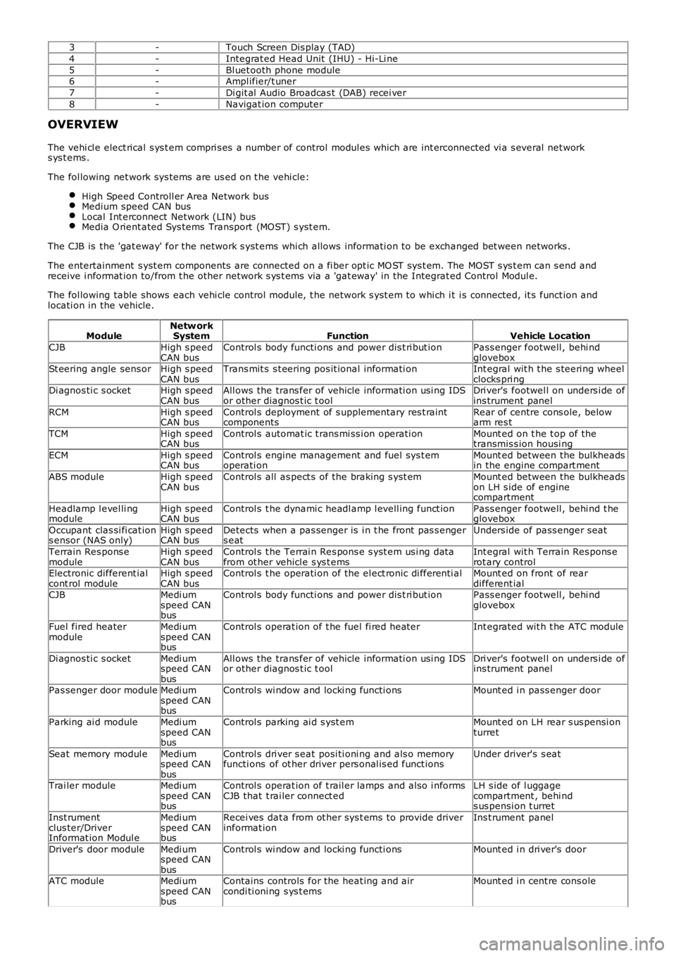
3-Touch Screen Dis play (TAD)
4-Integrat ed Head Unit (IHU) - Hi-Li ne
5-Bl uet ooth phone module6-Ampl ifier/t uner
7-Di git al Audio Broadcas t (DAB) recei ver
8-Navigat ion computer
OVERVIEW
The vehi cl e elect rical s ys t em compri s es a number of control modul es which are int erconnected vi a s everal net works ys t ems .
The fol lowing net work sys tems are us ed on t he vehi cle:
High Speed Controll er Area Network busMedium speed CAN busLocal Int erconnect Network (LIN) busMedia O rient ated Sys tems Transport (MOST) s yst em.
The CJB is the 'gat eway' for the net work s yst ems whi ch allows informati on to be exchanged bet ween networks .
The entertainment s yst em components are connected on a fi ber opt ic MO ST sys t em. The MOST s ys t em can s end andreceive i nformat ion to/from t he other network s ys t ems via a 'gat eway' in the Integrat ed Control Modul e.
The fol lowing table shows each vehi cle control modul e, t he network s yst em to whi ch it i s connected, it s funct ion andlocati on in the vehicle.
ModuleNetw orkSystemFunctionVehicle Location
CJBHigh s peedCAN busControl s body functi ons and power dis t ri but ionPass enger footwell , behi ndgloveboxSt eering angle sens orHigh s peedCAN busTrans mit s s t eering pos it ional informati onInt egral wit h t he s teeri ng wheelclocks pri ngDi agnos ti c s ocketHigh s peedCAN busAll ows the trans fer of vehicle informati on usi ng IDSor other diagnos t ic t oolDri ver's footwel l on unders i de ofins trument panel
RCMHigh s peedCAN busControl s deployment of s upplementary res t raintcomponentsRear of centre cons ole, belowarm res t
TCMHigh s peedCAN busControl s automat ic t rans mi ss i on operati onMount ed on t he t op of thetransmis s ion housi ng
ECMHigh s peedCAN busControl s engine management and fuel sys t emoperati onMount ed between the bulkheadsin the engine compart ment
ABS moduleHigh s peedCAN busControl s all as pect s of the braking s yst emMount ed between the bulkheadson LH s ide of enginecompartment
Headlamp l evel li ngmoduleHigh s peedCAN busControl s t he dynami c headl amp l evell ing funct ionPass enger footwell , behi nd t heglovebox
Occupant clas si fi cat ions ensor (NAS only)High s peedCAN busDetects when a pas senger is i n t he front pas s engers eatUnders ide of pass enger seat
Terrain Res pons emoduleHigh s peedCAN busControl s t he Terrai n Res pons e s yst em us i ng dat afrom ot her vehicl e s ys t emsInt egral wit h Terrain Res pons erot ary controlElectronic different ialcont rol moduleHigh s peedCAN busControl s t he operati on of the el ect ronic di fferenti alMount ed on front of reardifferent ialCJBMedi umspeed CANbus
Control s body functi ons and power dis t ri but ionPass enger footwell , behi ndglovebox
Fuel fired heatermoduleMedi umspeed CANbus
Control s operat ion of t he fuel fi red heaterInt egrated wit h t he ATC module
Di agnos ti c s ocketMedi umspeed CANbus
All ows the trans fer of vehicle informati on usi ng IDSor other diagnos t ic t oolDri ver's footwel l on unders i de ofins trument panel
Pas senger door moduleMedi umspeed CANbus
Control s wi ndow and locki ng functi onsMount ed i n pass enger door
Parking ai d moduleMedi umspeed CANbus
Control s parking ai d s yst emMount ed on LH rear s us pensi onturret
Seat memory modul eMedi umspeed CANbus
Control s dri ver s eat posi ti oni ng and als o memoryfuncti ons of ot her driver pers onal is ed funct ionsUnder driver's s eat
Trai ler moduleMedi umspeed CANbus
Control s operat ion of t rail er lamps and als o i nformsCJB that t rai ler connect edLH s ide of l uggagecompartment , behi nds us pensi on t urret
Inst rumentclus ter/DriverInformat ion Modul e
Medi umspeed CANbus
Recei ves dat a from ot her sys t ems to provide driverinformat ionIns t rument panel
Driver's door moduleMedi umspeed CANbus
Control s wi ndow and locki ng functi onsMount ed i n dri ver's door
ATC moduleMedi umspeed CANbus
Contains controls for the heat ing and aircondi ti oni ng s ys t emsMount ed i n cent re cons ole
Page 2073 of 3229
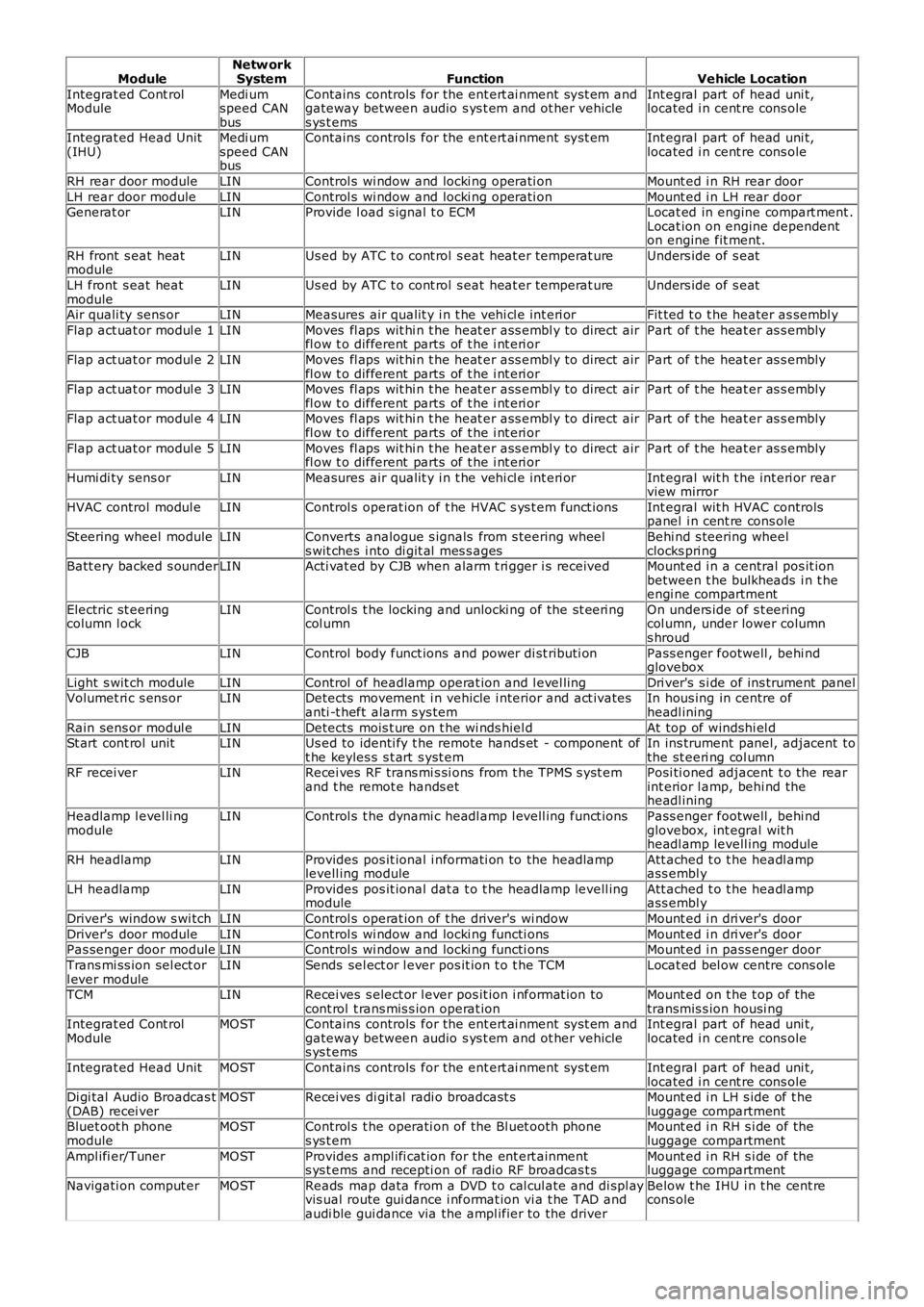
ModuleNetw orkSystemFunctionVehicle Location
Integrat ed Cont rolModuleMedi umspeed CANbus
Contains controls for the ent ert ai nment sys t em andgateway between audio s ys t em and ot her vehicles ys t ems
Int egral part of head uni t,located i n cent re cons ole
Integrat ed Head Unit(IHU)Medi umspeed CANbus
Contains controls for the ent ert ai nment sys t emInt egral part of head uni t,located i n cent re cons ole
RH rear door moduleLINControl s wi ndow and locki ng operati onMount ed i n RH rear door
LH rear door moduleLINControl s wi ndow and locki ng operati onMount ed i n LH rear doorGenerat orLINProvide l oad s ignal t o ECMLocat ed in engine compart ment .Locat ion on engine dependenton engine fit ment.
RH front s eat heatmoduleLINUs ed by ATC t o cont rol s eat heat er temperat ureUnders ide of s eat
LH front s eat heatmoduleLINUs ed by ATC t o cont rol s eat heat er temperat ureUnders ide of s eat
Air quali ty sens orLINMeasures air qualit y i n t he vehi cl e int eri orFit ted t o t he heater as sembl y
Flap act uat or modul e 1LINMoves fl aps wit hi n t he heat er ass embl y to direct airfl ow t o different parts of t he i nt eri orPart of t he heat er as s embly
Flap act uat or modul e 2LINMoves fl aps wit hi n t he heat er ass embl y to direct airfl ow t o different parts of t he i nt eri orPart of t he heat er as s embly
Flap act uat or modul e 3LINMoves fl aps wit hi n t he heat er ass embl y to direct airfl ow t o different parts of t he i nt eri orPart of t he heat er as s embly
Flap act uat or modul e 4LINMoves fl aps wit hi n t he heat er ass embl y to direct airfl ow t o different parts of t he i nt eri orPart of t he heat er as s embly
Flap act uat or modul e 5LINMoves fl aps wit hi n t he heat er ass embl y to direct airfl ow t o different parts of t he i nt eri orPart of t he heat er as s embly
Humi di ty sens orLINMeasures air qualit y i n t he vehi cl e int eri orInt egral wit h t he int eri or rearview mirror
HVAC control modul eLINControl s operat ion of t he HVAC s ys t em funct ionsInt egral wit h HVAC controlspanel i n cent re cons ole
St eering wheel moduleLINConverts analogue s ignals from s teering wheels wit ches i nto di git al mes s agesBehi nd s teering wheelclocks pri ngBatt ery backed s ounderLINActi vat ed by CJB when alarm t ri gger i s receivedMount ed i n a central pos it ionbetween t he bulkheads i n t heengi ne compartment
Electric st eeringcolumn l ockLINControl s t he locking and unlocki ng of the st eeri ngcol umnOn unders ide of s t eeringcol umn, under lower columns hroud
CJBLINControl body funct ions and power di st ributi onPass enger footwell , behi ndglovebox
Light s wit ch moduleLINControl of headlamp operat ion and l evel lingDri ver's s i de of ins trument panelVolumet ri c s ens orLINDetects movement i n vehicle i nterior and act ivatesanti -t heft alarm s ys temIn hous ing in centre ofheadl ining
Rain sens or modul eLINDetects mois t ure on t he wi nds hiel dAt top of windshi el dSt art cont rol unitLINUs ed to identi fy t he remote hands et - component oft he keyles s s t art s yst emIn ins trument panel, adjacent tothe st eeri ng col umnRF recei verLINRecei ves RF trans mi s si ons from t he TPMS s yst emand t he remot e hands etPosi ti oned adjacent t o the rearint erior l amp, behi nd theheadl ining
Headlamp l evel li ngmoduleLINControl s t he dynami c headl amp l evell ing funct ionsPass enger footwell , behi ndglovebox, int egral wit hheadl amp levell ing module
RH headlampLINProvides pos it ional i nformati on to the headlamplevell ing moduleAtt ached t o t he headl ampass embl y
LH headlampLINProvides pos it ional dat a t o t he headlamp levell ingmoduleAtt ached t o t he headl ampass embl y
Driver's window s wi tchLINControl s operat ion of t he driver's wi ndowMount ed i n dri ver's door
Driver's door moduleLINControl s wi ndow and locki ng functi onsMount ed i n dri ver's doorPas senger door moduleLINControl s wi ndow and locki ng functi onsMount ed i n pass enger door
Trans mi ss ion sel ect orl ever moduleLINSends sel ect or l ever pos it ion t o t he TCMLocat ed bel ow centre cons ole
TCMLINRecei ves s elect or l ever pos it ion i nformat ion tocont rol t rans mis s ion operat ionMount ed on t he t op of thetransmis s ion housi ngIntegrat ed Cont rolModuleMOSTContains controls for the ent ert ai nment sys t em andgateway between audio s ys t em and ot her vehicles ys t ems
Int egral part of head uni t,located i n cent re cons ole
Integrat ed Head UnitMOSTContains controls for the ent ert ai nment sys t emInt egral part of head uni t,located i n cent re cons oleDi gi tal Audio Broadcas t(DAB) recei verMOSTRecei ves di git al radi o broadcast sMount ed i n LH s ide of t heluggage compartmentBluet oot h phonemoduleMOSTControl s t he operati on of the Bl uet ooth phones ys t emMount ed i n RH s i de of theluggage compartment
Ampl ifi er/TunerMOSTProvides ampl ifi cat ion for the ent ert ainments ys t ems and recepti on of radio RF broadcas t sMount ed i n RH s i de of theluggage compartment
Navigati on comput erMOSTReads map data from a DVD t o cal cul ate and di spl ayvis ual route gui dance i nformat ion vi a t he TAD andaudi ble gui dance via the ampl ifier to the driver
Below t he IHU i n t he cent recons ole
Page 2452 of 3229
Publi s hed: 21-Nov-2011
Safety Belt System - Safety Belt System
Diagnosi s and Tes ti ng
Principle of Operation
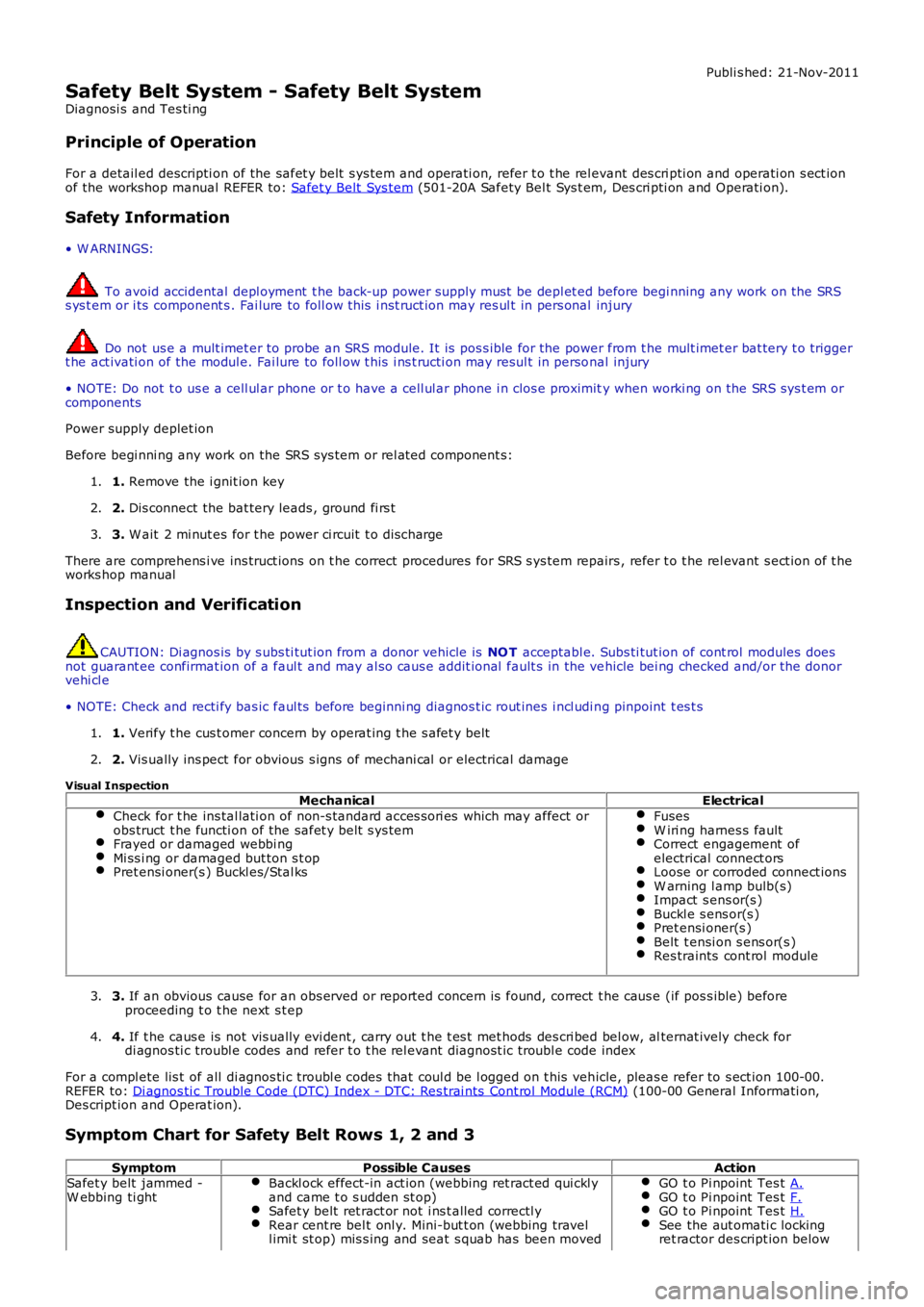
For a detail ed descripti on of the safet y belt s ys tem and operati on, refer t o t he relevant des cri pti on and operati on s ect ionof the workshop manual REFER to: Safet y Belt Sys tem (501-20A Safety Bel t Sys t em, Des cri pti on and Operati on).
Safety Information
• W ARNINGS:
To avoid accidental depl oyment t he back-up power supply must be depl et ed before begi nning any work on the SRSs ys t em or i ts component s . Fai lure to foll ow t his i nst ruct ion may res ul t in pers onal injury
Do not us e a mult imet er to probe an SRS module. It is pos s ible for the power from the mult imet er bat tery t o triggert he act ivati on of the modul e. Fai lure to foll ow t his i ns t ructi on may resul t in personal injury
• NOTE: Do not t o us e a cell ul ar phone or t o have a cell ul ar phone i n clos e proximity when worki ng on the SRS sys t em orcomponents
Power supply deplet ion
Before begi nni ng any work on the SRS sys tem or rel at ed component s:
1. Remove the i gnit ion key1.
2. Dis connect the bat tery leads , ground fi rs t2.
3. W ait 2 mi nut es for t he power ci rcuit t o dis charge3.
There are comprehens i ve ins truct ions on t he correct procedures for SRS s ys tem repairs , refer t o t he rel evant s ect ion of t heworks hop manual
Inspection and Verification
CAUTION: Di agnos is by s ubs ti tut ion from a donor vehicle is NO T acceptabl e. Subs ti tut ion of cont rol modules doesnot guarant ee confirmat ion of a faul t and may al so caus e addit ional fault s in the vehicle bei ng checked and/or the donorvehi cl e
• NOTE: Check and recti fy bas ic faul ts before beginni ng diagnos t ic rout ines i ncl udi ng pinpoint t es t s
1. Verify t he cus t omer concern by operat ing t he s afet y belt1.
2. Vis ually ins pect for obvious s igns of mechani cal or electrical damage2.
Visual InspectionMechanicalElectrical
Check for t he ins tal lati on of non-s tandard acces s ori es which may affect orobs truct t he functi on of the safet y belt s ys temFrayed or damaged webbi ngMi ss i ng or damaged but ton s t opPret ensi oner(s ) Buckl es/Stal ks
FusesW iri ng harnes s faultCorrect engagement ofelectrical connect orsLoose or corroded connect ionsW arning l amp bulb(s)Impact s ens or(s )Buckl e s ens or(s )Pret ensi oner(s )Belt t ensi on s ens or(s )Res traints cont rol module
3. If an obvious cause for an obs erved or report ed concern is found, correct t he caus e (if pos s ible) beforeproceeding t o t he next s t ep3.
4. If t he caus e is not vis ually evi dent , carry out t he t es t met hods des cri bed bel ow, alternat ively check fordi agnos ti c troubl e codes and refer t o t he rel evant diagnost ic troubl e code index4.
For a compl ete lis t of all di agnos ti c troubl e codes that coul d be l ogged on t his vehicle, pleas e refer to s ect ion 100-00.REFER to: Di agnos ti c Trouble Code (DTC) Index - DTC: Res trai nts Cont rol Module (RCM) (100-00 General Informati on,Des cript ion and Operat ion).
Symptom Chart for Safety Belt Rows 1, 2 and 3
SymptomPossible CausesActionSafet y belt jammed -W ebbing ti ghtBackl ock effect-in act ion (webbing ret ract ed qui ckl yand came t o s udden st op)Safet y belt ret ract or not i ns t alled correctl yRear cent re bel t onl y. Mini-but t on (webbing travell imi t st op) mis s ing and seat s quab has been moved
GO t o Pi npoint Tes t A.GO t o Pi npoint Tes t F.GO t o Pi npoint Tes t H.See the aut omati c lockingret ractor des cript ion below
Page 2521 of 3229
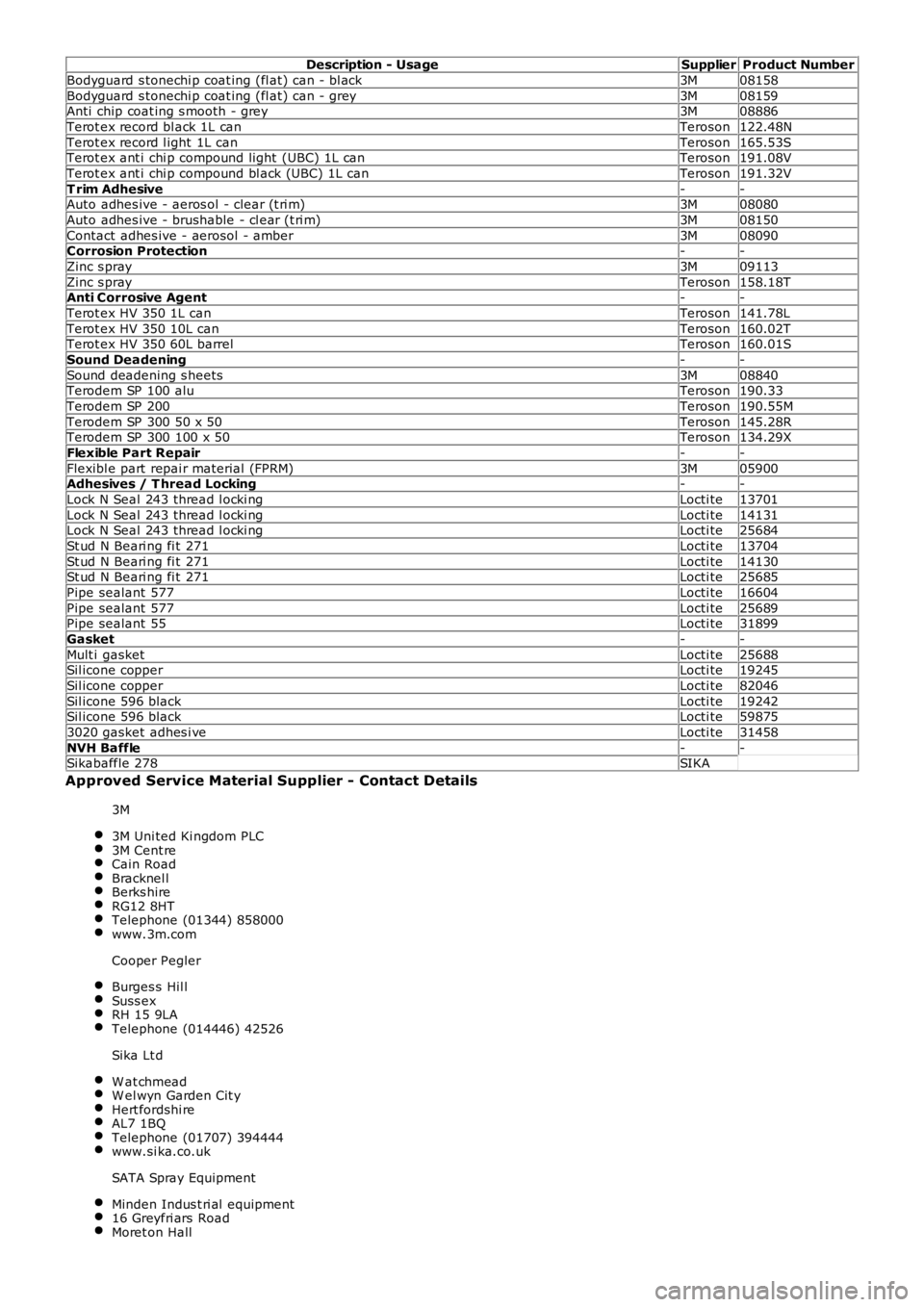
Description - UsageSupplierProduct Number
Bodyguard s tonechi p coat ing (fl at) can - bl ack3M08158
Bodyguard s tonechi p coat ing (fl at) can - grey3M08159Anti chip coat ing s mooth - grey3M08886
Terot ex record bl ack 1L canTeroson122.48N
Terot ex record l ight 1L canTeroson165.53STerot ex ant i chi p compound light (UBC) 1L canTeroson191.08V
Terot ex ant i chi p compound bl ack (UBC) 1L canTeroson191.32V
T rim Adhesive--Auto adhes ive - aeros ol - clear (t ri m)3M08080
Auto adhes ive - brushable - cl ear (t ri m)3M08150
Contact adhes ive - aerosol - amber3M08090Corrosion Protection--
Zinc s pray3M09113
Zinc s prayTeroson158.18TAnti Corrosive Agent--
Terot ex HV 350 1L canTeroson141.78L
Terot ex HV 350 10L canTeroson160.02TTerot ex HV 350 60L barrelTeroson160.01S
Sound Deadening--
Sound deadening s heets3M08840Terodem SP 100 aluTeroson190.33
Terodem SP 200Teroson190.55M
Terodem SP 300 50 x 50Teroson145.28RTerodem SP 300 100 x 50Teroson134.29X
Flexible Part Repair--
Flexibl e part repai r material (FPRM)3M05900Adhesives / T hread Locking--
Lock N Seal 243 thread l ocki ngLocti te13701
Lock N Seal 243 thread l ocki ngLocti te14131Lock N Seal 243 thread l ocki ngLocti te25684
St ud N Beari ng fi t 271Locti te13704
St ud N Beari ng fi t 271Locti te14130St ud N Beari ng fi t 271Locti te25685
Pipe sealant 577Locti te16604
Pipe sealant 577Locti te25689Pipe sealant 55Locti te31899
Gasket--
Mult i gasketLocti te25688Sil icone copperLocti te19245
Sil icone copperLocti te82046
Sil icone 596 blackLocti te19242Sil icone 596 blackLocti te59875
3020 gasket adhes i veLocti te31458
NVH Baffle--Sikabaffle 278SIKA
Approved Service Material Supplier - Contact Details
3M
3M Uni ted Ki ngdom PLC3M Cent reCain RoadBracknel lBerks hireRG12 8HTTelephone (01344) 858000www.3m.com
Cooper Pegler
Burges s Hil lSuss exRH 15 9LATelephone (014446) 42526
Sika Lt d
W at chmeadW el wyn Garden Cit yHert fordshi reAL7 1BQTelephone (01707) 394444www.si ka.co.uk
SATA Spray Equipment
Minden Indus t ri al equipment16 Greyfri ars RoadMoret on Hall
Page 2522 of 3229
Bury St EdmundsSuffol kIP32 7DXTelephone (01284) 760791www.sat a.com
Henkel Loct it e Adhesi ves Li mi ted
Technologies Hous eW ood Lane EndHemel Hempst eadHert fordshi reHP2 4RQTelephone (01442) 278000www.locti te.co.uk
Teros on
Henkel LtdApollo Court2 Bi shops Square Bus ines s ParkHatfiel dHert fordshi reAL10 9EYTelephone (01707) 635000www.henkel.co.uk
Underbody sealer
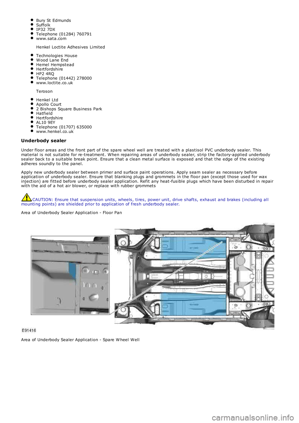
Under floor areas and t he front part of the spare wheel wel l are t reat ed wit h a pl ast is ol PVC underbody sealer. Thi smat erial i s not sui table for re-treatment . W hen repairing areas of underbody s ealer, s t ri p t he factory-appl ied underbodys eal er back t o a s uit able break poi nt. Ens ure t hat a clean met al s urface is expos ed and that t he edge of t he exis t ingadheres s oundly to the panel.
Apply new underbody s eal er bet ween pri mer and s urface paint operat ions . Appl y s eam seal er as neces sary beforeappl icati on of underbody s ealer. Ens ure that blanking plugs and grommets in t he floor pan (except t hose used for waxinject ion) are fi tt ed before underbody s ealer appl icati on. Refit any heat-fus ibl e plugs which have been dis t urbed in repairwit h t he aid of a hot ai r blower, or repl ace wit h rubber grommet s
CAUTION: Ens ure t hat sus pens i on uni ts , wheels , ti res , power uni t, drive s haft s, exhaus t and brakes (including al lmounti ng points ) are s hi elded pri or to appl icat ion of fres h underbody s eal er.
Area of Underbody Sealer Appl icati on - Floor Pan
Area of Underbody Sealer Appl icati on - Spare W heel W el l
Page 2726 of 3229

Contents
6
L
TRACK SELECTION....................................... 246
COMPACT DISC PAUSE................................ 246
FAST FORWARD/REVERSE .......................... 247
COMPACT DISC FUNCTION MENU ............... 247
COMPACT DISC DISPLAY OPTIONS ............ 247
SHUFFLE/RANDOM ...................................... 247
REPEAT COMPACT DISC TRACKS ............... 248
COMPACT DISC TRACK SCANNING ............. 248
MP3 FILE PLAYBACK ................................... 249
Auxiliary input (AUX IN) socket
AUXILIARY INPUT (AUX IN) SOCKET........... 250
Rear passenger controls
REAR SEAT CONTROLS ............................... 252
HEADPHONES .............................................. 253
Telephone
GENERAL INFORMATION ............................. 254
TELEPHONE CONTROLS .............................. 255
BLUETOOTH SETUP ..................................... 256
TELEPHONE SETUP...................................... 258
USING THE TELEPHONE .............................. 261
PHONEBOOK ................................................ 266
TELEPHONE VOICE CONTROL...................... 270
Page 2738 of 3229

18
Quick start
L
1. Exterior lamps master switch
2. Direction indicators/headlam ps/trip computer switch
3. Cruise control switches
4. Instrument pack
5. Audio/telephone switches
6. Washer/wiper switch
7. Start stop engine button
8. Master unlock switch
9. Hazard warning switch
10. Master lock switch
11. Audio unit
12. Heater/air conditioning controls
13. Dynamic Stability Control (DSC) switch
14. Gear selector
15. Touch screen
16. Parking brake
17. Terrain Response control switch
18. Hill Descent Control (HDC) switch
19. Starter control unit
20. Steering column adjustment lever
21. Horn switches
22. Facia illumination dimmer control
Page 2748 of 3229
28
Quick start
L
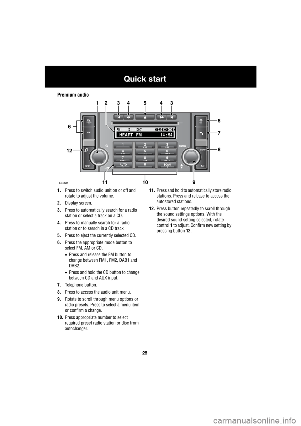
Premium audio
1. Press to switch audio unit on or off and
rotate to adjust the volume.
2. Display screen.
3. Press to automatically search for a radio
station or select a track on a CD.
4. Press to manually search for a radio
station or to search in a CD track
5. Press to eject the currently selected CD.
6. Press the appropriate mode button to
select FM, AM or CD.
• Press and release the FM button to
change between FM1, FM2, DAB1 and
DAB2.
• Press and hold the CD button to change
between CD and AUX input.
7. Telephone button.
8. Press to access the audio unit menu.
9. Rotate to scroll through menu options or
radio presets. Press to select a menu item
or confirm a change.
10. Press appropriate number to select
required preset radio station or disc from
autochanger. 11.
Press and hold to automatically store radio
stations. Press and release to access the
autostored stations.
12. Press button repeatedly to scroll through
the sound settings options. With the
desired sound setti ng selected, rotate
control 1 to adjust. Confir m new setting by
pressing button 12.
TA
NEWSPTY100.7
FM1
14 : 54
HEART FM
1234 6
2
E84422
34543
6
7
8
21
91011
12
6