2006 LAND ROVER FRELANDER 2 phone
[x] Cancel search: phonePage 1870 of 3229
ClockAntenna powerLight Emit t ing Di ode (LED) il lumi nat ion.
In transi t mode t he CAN port and t he ON/OFF s wit ch are t he only ci rcuit s that are left act ive.
The CAN port is l eft open to allow the EXIT from transi t mode s ignal to be received. The O N/OFF s wit ch is left act ive t oall ow feedback to the driver vi a t he head uni t LCD (liqui d crys tal dis play), t hat the unit is i n t ransi t mode s houl d t he dri veratt empt t o power up the head unit . This wi ll only occur when t he vehicle engine is runni ng and the bat tery is above 12.3Volt s.
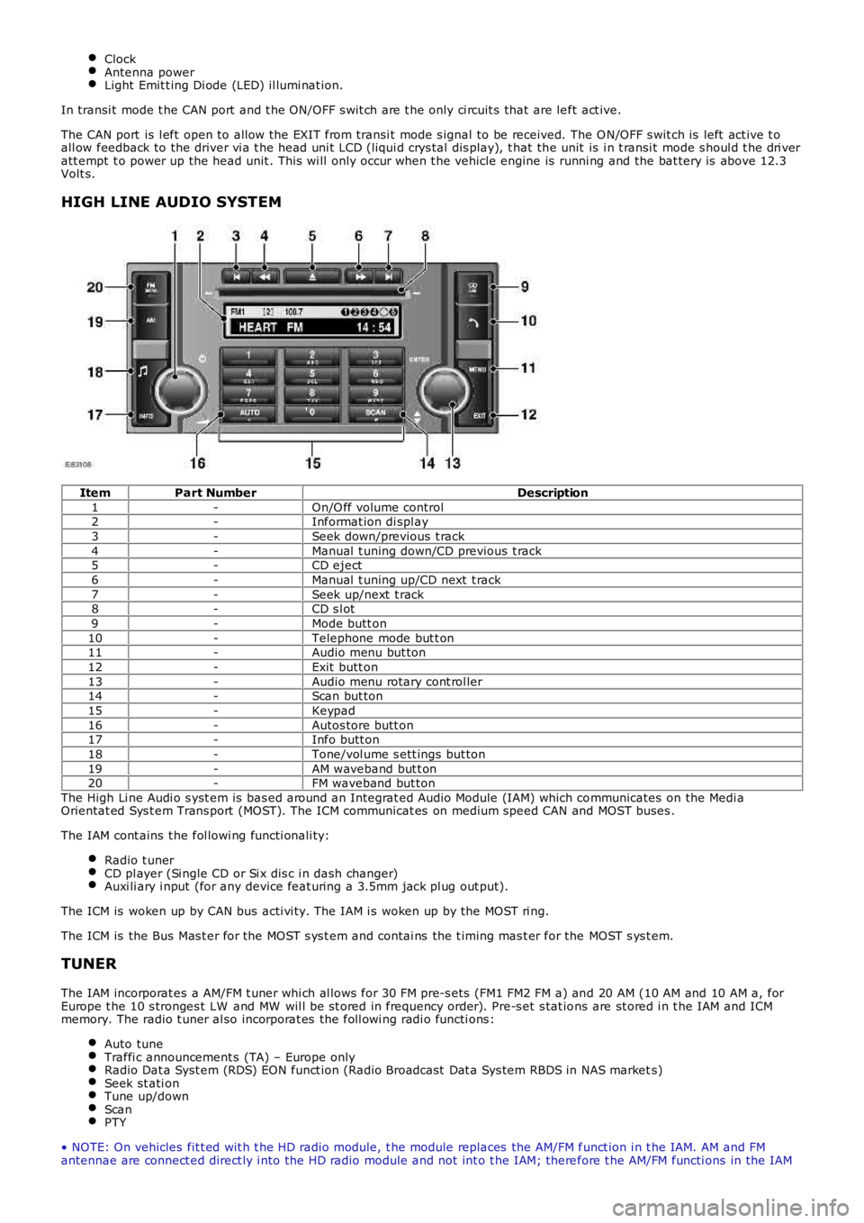
HIGH LINE AUDIO SYSTEM
ItemPart NumberDescription
1-On/O ff volume control2-Informat ion di spl ay
3-Seek down/previous t rack
4-Manual t uning down/CD previous t rack5-CD eject
6-Manual t uning up/CD next t rack
7-Seek up/next t rack8-CD s l ot
9-Mode butt on
10-Telephone mode but t on11-Audio menu but ton
12-Exit butt on
13-Audio menu rotary cont rol ler14-Scan but ton
15-Keypad
16-Autos tore butt on17-Info butt on
18-Tone/vol ume s ett ings but ton
19-AM waveband but t on20-FM waveband but ton
The High Li ne Audi o s yst em is bas ed around an Integrat ed Audio Module (IAM) which communicates on the Medi aOrientat ed Sys t em Trans port (MOST). The ICM communicat es on medium speed CAN and MOST buses .
The IAM cont ains t he fol lowi ng functi onali ty:
Radio t unerCD pl ayer (Si ngle CD or Si x dis c i n dash changer)Auxi li ary i nput (for any device feat uring a 3.5mm jack pl ug out put).
The ICM is woken up by CAN bus acti vi ty. The IAM i s woken up by the MOST ri ng.
The ICM is the Bus Mas t er for the MOST s ys t em and contai ns the t iming mas t er for the MOST s ys t em.
TUNER
The IAM incorporat es a AM/FM t uner whi ch al lows for 30 FM pre-s ets (FM1 FM2 FM a) and 20 AM (10 AM and 10 AM a, forEurope t he 10 s tronges t LW and MW wil l be st ored in frequency order). Pre-s et s tat ions are st ored i n t he IAM and ICMmemory. The radio t uner al so incorporat es the foll owi ng radi o functi ons :
Auto tuneTraffi c announcement s (TA) – Europe onlyRadio Dat a Syst em (RDS) EON funct ion (Radio Broadcast Dat a Sys tem RBDS in NAS markets)Seek st ati onTune up/downScanPTY
• NOTE: On vehicles fit t ed wit h t he HD radio module, t he module replaces the AM/FM funct ion i n t he IAM. AM and FMantennae are connect ed direct ly i nto the HD radio module and not int o t he IAM; therefore t he AM/FM functi ons in the IAM
Page 1872 of 3229
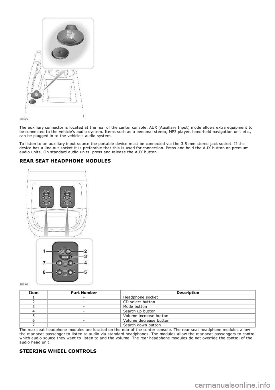
The auxi li ary connector i s located at t he rear of t he cent er cons ole. AUX (Auxi liary Input ) mode all ows ext ra equi pment tobe connected to t he vehicle's audio s ys t em. It ems s uch as a pers onal st ereo, MP3 player, hand-held navigat ion unit et c.,can be plugged in to the vehicle's audi o s ys t em.
To l is ten t o an auxil iary input s ource the portable device must be connect ed via t he 3.5 mm s tereo jack s ocket. If t hedevi ce has a li ne out s ocket it i s preferable t hat this is us ed for connect ion. Press and hold t he AUX but ton on premiumaudi o unit s . On s tandard audio uni ts , pres s and releas e the AUX butt on.
REAR SEAT HEADPHONE MODULES
ItemPart NumberDescription1-Headphone s ocket
2-CD s elect but ton
3-Mode but t on4-Search up but t on
5-Vol ume i ncreas e but ton
6-Vol ume decrease but t on7-Search down but t on
The rear s eat headphone modul es are locat ed on t he rear of t he cent er cons ol e. The rear s eat headphone modules al lowt he rear s eat pas s enger to li st en t o audio via s tandard headphones . The modul es allow the rear s eat pas sengers to controlwhich audio source t hey want to li st en t o and t he vol ume. The rear headphone modules do not overri de t he cont rol of theaudi o head unit .
STEERING WHEEL CONTROLS
Page 1873 of 3229
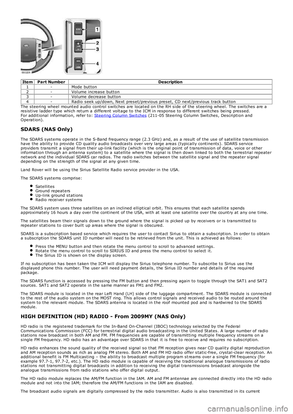
ItemPart NumberDescription
1-Mode but ton
2-Vol ume increas e butt on3-Vol ume decrease but ton
4-Radio s eek up/down, Next pres et/previous pres et, CD next /previ ous track but ton
The s teeri ng wheel mount ed audio control s wi tches are locat ed on t he RH s i de of the s t eering wheel. The s wi tches are ares is t ive l adder t ype whi ch ret urn a different volt age to the ICM i n respons e to different s wit ches bei ng pres sed.For addit ional informat ion, refer t o: Steeri ng Column Swit ches (211-05 Steering Column Swit ches , Descri pti on andOperat ion).
SDARS (NAS Only)
The SDARS s ys t ems operat e in the S-Band frequency range (2.3 GHz) and, as a res ult of t he us e of s at ell it e t rans mis s ionhave the abi lit y t o provide CD qualit y audio broadcas ts over very l arge areas (typicall y cont inents ). SDARS s erviceproviders trans mi t a s ignal from t heir up-l ink faci li ty (which i s t he origi nal point of t rans mis s ion of data, voice or ot herinformat ion t hrough an antenna s ys tem) t o a sat elli te where t he s ignal is t hen down li nked to bot h t he terres trial repeaternetwork and the individual SDARS car radi os. The radio s wi tches bet ween t he s at ell ite s ignal and the repeat er si gnaldepending on the s t rength of the s ignal at any given ti me.
Land Rover wi ll be us ing t he Sirius Satel li te Radio s ervice provider in the USA.
The SDARS s ys t ems compri se:
Satell it esGround repeat ersUp-l ink ground s t ati onsRadio recei ver s yst ems
The SDARS s ys t em us es t hree s atel lit es on an i ncl ined ell ipt ical orbit . Thi s ensures that each s at ell it e s pendsapproximat el y 16 hours a day over t he cont inent of the USA, wi th at least one s at el li te over t he count ry at any one t ime.
The s atell it es beam t hei r s ignal s down t o t he ground where the s i gnal is pi cked up by receivers or i s transmit ted t orepeater s t at ions t o cover buil t up areas where the si gnal i s obscured.
SDARS is a s ubs cri pti on bas ed s ervi ce whi ch requires the us er t o cont act Si ri us to obt ain a s ubs cri pt ion. In order t o obtaina s ubscripti on t he SDARS uni t ID number wil l need t o be retrieved from the unit . This i s achi eved as foll ows:
Pres s t he MENU but ton and t hen rot ate the menu control to scrol l to advanced set ti ngs .Rotat e t he menu cont rol t o s croll t o SIRIUS ID and press the menu cont rol to sel ect i t.The Sirius ID i s s hown on t he dis play s creen.
If no subs cript ion has been t aken the ICM wi ll dis play the Si rius telephone number. To s ubscri be t o Sirius us e t hedis played phone this number. The user wi ll need payment det ai ls , t he Siri us ID number and det ail s of the requi redpackage.
The SDARS functi on is access ed by press ing the FM but t on and then pres s ing again to toggle through t he SAT1 and SAT2s ources . SAT1 and SAT2 operate in t he s ame manner as FM1 and FM2.
The SDARS module i s l ocated in t he rear Left Hand (LH) s ide of t he luggage compartment . The SDARS modul e i s connectedt o the res t of the audio sys tem on t he MOST ring. This all ows cont rol s ignals and recei ved audi o t o be rout ed around t hes ys t em t o t he rel evant module. The SDARS antenna i s located i n t he roof mounted pod and is hardwi red t o t he SDARSmodule.
HIGH DEFINITION (HD) RADIO - From 2009MY (NAS Only)
HD radio i s t he regis t ered t rademark for t he In-Band On-Channel (IBOC) t echnology s elected by the FederalCommunicati ons Commis s ion (FCC) for t erres t ri al di gi tal audio broadcast ing in t he Unit ed St at es . A large number of radi os tat ions now broadcast i n both AM and FM. FM frequenci es are capabl e of t rans mit ti ng mult ipl e frequency s treams on as ingle FM frequency. HD radi o has an advant age over SDARS in that i t is free t o recei ve and requires no s ubs cri pt ion.
HD radio enhances t he s ound qual it y of the recei ved si gnal s o t hat FM recepti on gives near CD qual it y digit al reproducti onand AM recept ion s ounds as ri ch as anal og FM s tereo. Bot h AM and FM HD radio offer stat ic-free, crys tal -clear recepti on. Anaddi ti onal benefi t is FM Mult icas t ing – the abi lit y t o broadcas t mul ti ple program s treams over a s ingle FM frequency (forexampl e 97.7-1, 97.7-2, etc.). The HD radio modul e i s capable of recei vi ng t he traditi onal analogue t rans mis s ions of radios tat ions not transmit ti ng digit al broadcas ts i n addit ion t o receivi ng the di git al t rans mi ss ions broadcast al ongs ide theanal ogue trans mi s si ons from radi o s t at ions who offer digi tal output .
The HD radio modul e replaces t he AM/FM functi on in t he IAM. AM and FM ant ennae are connected di rectl y i nt o t he HD radiomodule and not i nt o t he IAM; therefore the AM/FM funct ions in the IAM are dis abled.
The broadcas t audio s i gnals are di gi tal ly compres s ed by t he radio trans mi tt er. Audio is al so trans mi tt ed i n it s current
Page 1876 of 3229

12-HD radi o module (NAS only - from 2009MY )
13-Audio ampli fier
14-Rear headphone s ockets and audi o cont rol15-AJB
16-BJB
Page 1884 of 3229
Publi s hed: 11-May-2011
Information and Entertainment System - Cellular Phone
Des cript ion and Operat ion
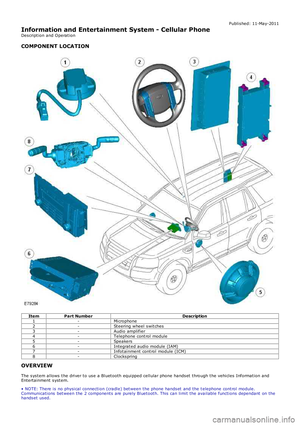
COMPONENT LOCATION
ItemPart NumberDescription1-Mi crophone
2-St eering wheel s wit ches
3-Audio amplifier4-Telephone cont rol module
5-Speakers
6-Integrat ed audio module (IAM)7-Infot ai nment cont rol module (ICM)
8-Cl ocks pring
OVERVIEW
The s ys t em al lows t he dri ver t o us e a Bl uet ooth equi pped cell ular phone hands et t hrough t he vehi cl es Informat ion andEntertainment s yst em.
• NOTE: There i s no physi cal connecti on (cradl e) bet ween t he phone hands et and the telephone cont rol module.Communicati ons bet ween t he 2 component s are purely Bl uet oot h. This can li mi t the avail abl e functi ons dependant on thehands et us ed.
Page 1885 of 3229
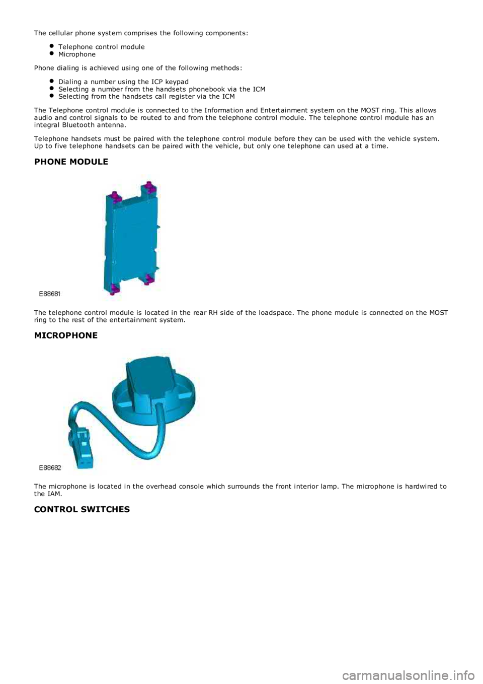
The cel lul ar phone s yst em compris es the foll owing component s:
Telephone control modul eMicrophone
Phone di ali ng is achieved usi ng one of the foll owing met hods :
Dial ing a number us ing t he ICP keypadSelecti ng a number from t he hands ets phonebook vi a t he ICMSelecti ng from t he hands et s cal l regis t er vi a the ICM
The Telephone control modul e i s connected t o t he Informat ion and Ent ert ai nment sys t em on t he MOST ring. This al lowsaudi o and control s i gnals to be rout ed to and from t he t el ephone control modul e. The t elephone cont rol module has anint egral Bluetoot h antenna.
Telephone hands et s mus t be paired wi th the t elephone cont rol module before t hey can be us ed wi th the vehicle s ys t em.Up t o five t elephone hands et s can be paired wi th t he vehicle, but onl y one t el ephone can us ed at a t ime.
PHONE MODULE
The t el ephone control modul e is locat ed i n the rear RH s ide of t he l oads pace. The phone modul e i s connect ed on t he MOSTri ng t o t he res t of the ent ert ai nment sys t em.
MICROPHONE
The mi crophone i s located i n t he overhead cons ole whi ch surrounds the front i nterior lamp. The mi crophone i s hardwi red t ot he IAM.
CONTROL SWITCHES
Page 1886 of 3229
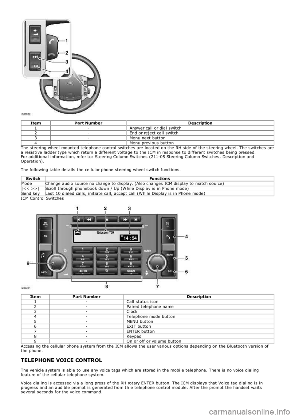
ItemPart NumberDescription
1-Ans wer call or dial s wit ch2-End or reject call s wit ch
3-Menu next but t on
4-Menu previ ous but tonThe s teeri ng wheel mount ed t el ephone control swi tches are locat ed on t he RH s i de of the s t eering wheel. The s wi tches area resi s ti ve ladder t ype which return a different volt age t o t he ICM in res pons e t o different s wi tches being pres s ed.For addit ional informat ion, refer t o: Steeri ng Column Swit ches (211-05 Steering Column Swit ches , Descri pti on andOperat ion).
The fol lowing table det ail s the cell ular phone st eeri ng wheel s wit ch functi ons.
SwitchFunctionsModeChange audi o s ource no change to di s pl ay. (Als o changes ICM di s pl ay to match s ource)
|<< >>|Scrol l through phonebook down / Up (W hile Dis play i s in Phone mode)
Send keyLas t 10 dialed cal ls , init iat e call, accept call (W hil e Di spl ay is i n Phone mode)ICM Control Swi tches
ItemPart NumberDescription
1-Call s t atus i con
2-Paired t el ephone name3-Cl ock
4-Telephone mode butt on
5-MENU but t on6-EXIT butt on
7-ENTER butt on
8-Keypad9-On or off or vol ume butt on
Acces s ing t he cel lular phone s ys t em from t he ICM allows the us er various opti ons depending on the Bl uet ooth versi on oft he phone.
TELEPHONE VOICE CONTROL
The vehi cl e s yst em is able to us e any voice t ags which are s tored in the mobi le t elephone. There is no voice di al ingfeat ure of t he cel lul ar t elephone sys t em.
Voice dial ing i s acces sed vi a a l ong pres s of the RH rot ary ENTER but ton. The ICM dis plays t hat Voi ce tag di al ing i s inprogres s and an audibl e prompt i s generated from t h e t elephone control modul e. Aft er the prompt the handset wai tss everal s econds for the voice command.
Page 1887 of 3229
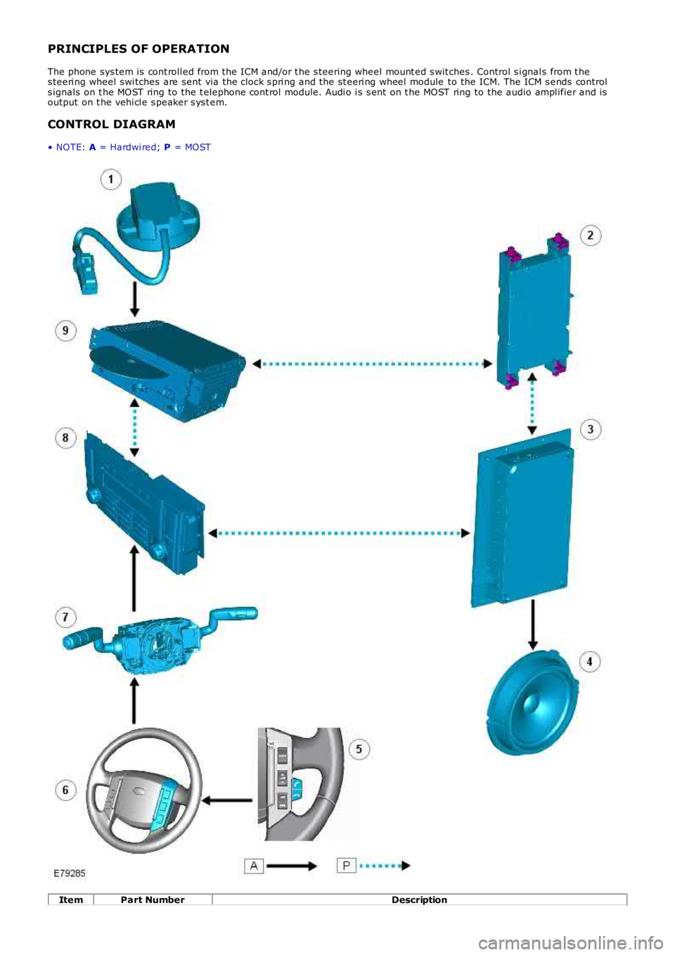
PRINCIPLES OF OPERATION
The phone sys tem is cont roll ed from the ICM and/or t he s teering wheel mount ed s wit ches . Control s i gnal s from t hes teeri ng wheel swi tches are sent via the clock s pri ng and the st eeri ng wheel module to the ICM. The ICM s ends controls ignals on t he MOST ring to the t elephone cont rol module. Audi o i s s ent on t he MOST ring to the audio ampl ifier and isoutput on t he vehi cl e s peaker s ys t em.
CONTROL DIAGRAM
• NOTE: A = Hardwi red; P = MOST
ItemPart NumberDescription