2006 LAND ROVER FRELANDER 2 phone
[x] Cancel search: phonePage 110 of 3229
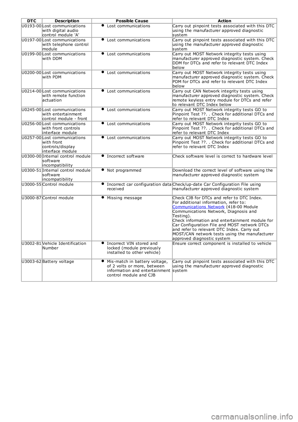
DT CDescriptionPossible CauseAction
U0193-00Lost communi cat ionswi th di git al audiocont rol module 'A'
Los t communicat ionsCarry out pi npoi nt tes ts as s oci ated wit h thi s DTCusi ng t he manufact urer approved diagnost ics ys t em
U0197-00Lost communi cat ionswi th t elephone cont rolmodule
Los t communicat ionsCarry out pi npoi nt tes ts as s oci ated wit h thi s DTCusi ng t he manufact urer approved diagnost ics ys t emU0199-00Lost communi cat ionswi th DDMLos t communicat ionsCarry out MOST Network int egrit y t est s us ingmanufacturer approved diagnost ic sys tem. CheckDDM for DTCs and refer t o relevant DTC Indexbel ow
U0200-00Lost communi cat ionswi th PDMLos t communicat ionsCarry out MOST Network int egrit y t est s us ingmanufacturer approved diagnost ic sys tem. CheckPDM for DTCs and refer t o rel evant DTC Indexbel ow
U0214-00Lost communi cat ionswi th remote functi onactuati on
Los t communicat ionsCarry out CAN Network int egrit y t est s us ingmanufacturer approved diagnost ic sys tem. Checkremot e keyl ess ent ry modul e for DTCs and referto relevant DTC Index below
U0245-00Lost communi cat ionswi th ent ert ai nmentcont rol module - front
Los t communicat ionsCarry out MOST Network int egrit y t est s GO toPinpoint Test ??. . Check for addi ti onal DTCs andrefer t o relevant DTC Index
U0256-00Lost communi cat ionswi th front control sint erface modul e
Los t communicat ionsCarry out MOST Network int egrit y t est s GO toPinpoint Test ??. . Check for addi ti onal DTCs andrefer t o relevant DTC IndexU0257-00Lost communi cat ionswi th frontcont rol s/dis playint erface modul e
Los t communicat ionsCarry out MOST Network int egrit y t est s GO toPinpoint Test ??. . Check for addi ti onal DTCs andrefer t o relevant DTC Index
U0300-00Int ernal cont rol modules oft wareincompati bili ty
Incorrect s oft wareCheck s oft ware level i s correct t o hardware level
U0300-51Int ernal cont rol modules oft wareincompati bili ty
Not programmedDownload t he correct level of s oft ware usi ng t hemanufacturer approved diagnost ic sys tem
U3000-55Control modul eIncorrect car confi gurati on datarecei vedCheck/up-dat e Car Configurat ion Fi le us i ngmanufacturer approved diagnost ic sys tem
U3000-87Control modul eMis si ng mes s ageCheck CJB for DTCs and refer t o DTC Index.For addit ional informati on, refer t o:Communicati ons Net work (418-00 ModuleCommunicati ons Net work, Di agnos is andTes t ing).Check i nformat ion and ent ert ainment module forCar Configurat ion Fil e and MOST net work DTCsand refer t o relevant DTC Index. Carry outMOST/CAN net work t es ts us ing the manufact urerapproved di agnos ti c s yst emU3002-81Vehicle Identi ficat ionNumberIncorrect VIN s tored andl ocked (module previ ous l yi nst all ed to other vehi cl e)
Ens ure correct component is ins tall ed t o vehi cl e
U3003-62Batt ery vol tageMis -mat ch in bat t ery volt age,of 2 vol ts or more, bet weeni nformati on and ent ert ainmentcontrol modul e and CJB
Carry out pi npoi nt tes ts as s oci ated wit h thi s DTCusi ng t he manufact urer approved diagnost ics ys t em
Page 153 of 3229

Publ is hed: 26-Oct -2011
General Information - Diagnostic Trouble Code (DTC) IndexDTC: High
Definition Radio Module (HDR)
Des cript ion and Operat ion
• NOTE: If a cont rol module or component i s s uspect and the vehicl e remai ns under manufacturer warrant y, refer t o t heW arranty Pol icy and Procedures manual (s ect ion B1.2), or determine i f any pri or approval program is i n operat ion, beforet he replacement of a component.
• NOTE: Generic scan t ool s may not read the codes li st ed, or may read only 5-digi t codes . Match t he 5 digi ts from t he s cant ool t o t he fi rs t 5 di gi ts of the 7-digit code li s ted t o i dent ify the fault (the last 2 digi ts gi ve ext ra informati on read by themanufacturer-approved di agnos ti c s ys t em).
• NOTE: W hen performing volt age or res is t ance t est s , always use a digi tal mult imeter (DMM) accurat e t o t hree deci malplaces, and wi th an up-t o-date cal ibrat ion cert ificate. W hen tes ti ng res is t ance al ways take t he res is t ance of t he DMMleads i nt o account .
• NOTE: Check and recti fy bas ic faul ts before beginni ng diagnos t ic rout ines i nvol vi ng pinpoint t es t s.
• NOTE: Ins pect connect ors for s igns of water ingres s , and pins for damage and/or corros ion.
• NOTE: If DTCs are recorded and, aft er performi ng the pi npoi nt tes ts , a fault is not present , an int ermi tt ent concern maybe t he caus e. Always check for loose connect ions and corroded terminals .
Des cript ion And Operat ion
For a detail ed descripti on of the cell ular phone sys tem, refer t o t he rel evant Des cript ion and Operat ion s ecti on in theworks hop manual . For addit ional informat ion, refer t o: Audi o Syst em (415-01 Informati on and Entertainment Sys tem,Des cript ion and Operat ion).
Digital Audio Control Module C (DAC MC )DT CDescriptionPossible CauseAction
B1A56-02Antenna -general si gnalfai lure
Antenna general si gnal failureRefer t o t he electrical gui des and check the IBOC radiomodule ci rcuit and t he antenna for s hort t o power, opencircui t, hi gh res is t ance. Clear the di agnos ti c t roublecode and ret est . If the di agnos ti c troubl e code pers is ts ,check and i nst all a new IBOC radio modul e, as required.Refer t o t he warranty poli cy and procedures manual , ordetermine if any pri or approval programme is inoperat ion, prior t o t he ins t al lat ion of a new modul eB1A56-11Antenna - circui ts hort t o groundIBOC radio module or antennacircuit s hort t o groundRefer t o t he electrical gui des and check the IBOC radiomodule ci rcuit and t he antenna for s hort ci rcuit t oground
B1A56-12Antenna - circui ts hort t o batt eryIBOC radio module or antennacircuit s hort t o powerRefer t o t he electrical gui des and check the IBOC radiomodule ci rcuit and t he antenna for s hort ci rcuit t opower
B1A56-13Antenna - circui topenIBOC radio module or antennacircuit open circui tRefer t o t he electrical gui des and check the IBOC radiomodule ci rcuit and t he antenna for open circui t
U200D-14Control ModuleOut put Power A -circui t short toground or open
IBOC radio module powers uppl y ci rcuit s hort t o groundor open ci rcuit
Refer t o t he electrical gui des and check the IBOC radiomodule divers it y power ci rcuit for short to ground, opencircui t
U3000-04Control Module -s yst em i nternalfai lures
IBOC radio module i nternalfai lureRenew t he IBO C radi o module
U3000-4AControl Module -incorrectcomponentins t al led
IBOC radio module i nternalincorrect component i ns t alled -The module has been i ns t alledto a vehicle not configured toaccept it
Us ing the manufact urer approved di agnos ti c s yst ems elect the vehicle configurat ion mai n menu, s el ectconfigure exis ti ng modules menu and program t hemodule
U3000-55Control Module -not configuredIBOC radio module notconfigured correct lyUs ing the manufact urer approved di agnos ti c s yst ems elect the vehicle configurat ion mai n menu, s el ectconfigure exis ti ng modules menu and program t hemodule
U3000-87Control Module -mi ss i ng mes sageMis s ing mess ageUs ing the manufact urer approved di agnos ti c s yst ems elect the vehicle configurat ion mai n menu, s el ectconfigure exis ti ng modules menu and program t hemoduleU3000-98Control Module -component ors yst em overt emperature
IBOC radio module componentor sys t em over temperat ureCons ider movi ng t he IBOC radio modul e t o prevent uni toverheati ng. Cool the vehicle int erior down by ens uri ngi t is i n t he s hade and have t he A/C on cool . W hen cool,clear t he diagnos t ic t rouble code and retes tU3003-62Batt ery Vol tage -s ignal comparefai lure
Mis mat ch in bat tery volt age of2 volt s or more for l onger than1 mi nute, between t hemeas ured batt ery volt age atthe IBOC radio modul e and t hebatt ery volt age s ignal s entfrom t he rear junct ion box
Refer t o t he electrical gui des and check that powers uppl y volt age at IBOC radio modul e and rear junct ionbox i s not di fferent by more than 2 vol ts . Recti fy asrequi red
Authori ng Templat e
Page 546 of 3229
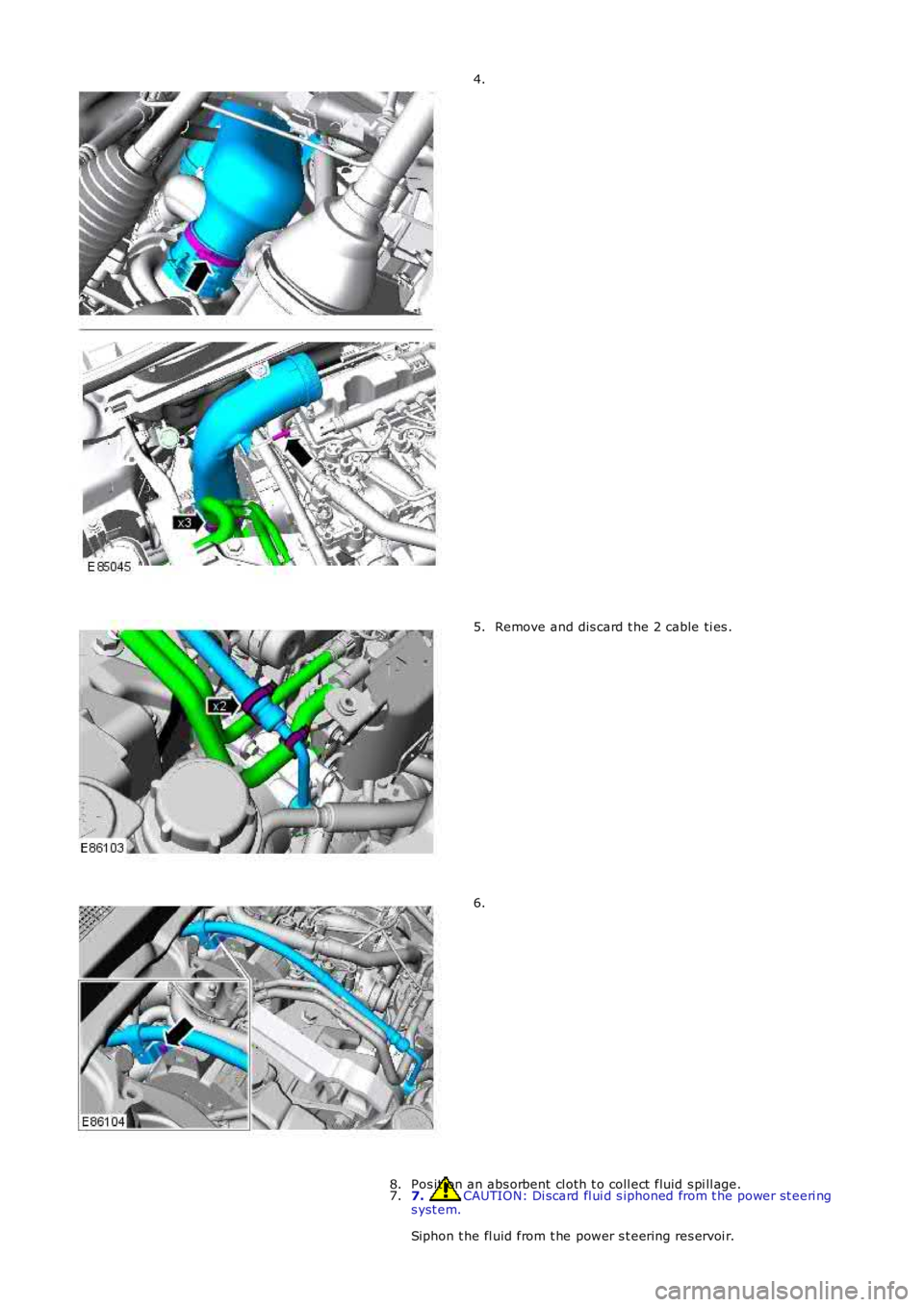
4.
Remove and dis card t he 2 cable ti es .5.
6.
7. CAUTION: Di scard fl ui d s iphoned from t he power st eeri ngs yst em.
Siphon t he fl uid from t he power s t eering res ervoi r.
7.Pos it ion an abs orbent cl oth t o coll ect fluid s pi ll age.8.
Page 548 of 3229
10 s econds .
W it h the engi ne at idle, s lowl y turn t he s teeri ng wheel and
hold on full l ock. Record t he pres s ure readi ng.
Repeat t he above procedure for t he other s ide. Record t he pres s ure readi ng.16.
W it h the engi ne at idle, rel ease the s t eering wheel. The press ure
s houl d be, at or bel ow, the pres s ure specified.
17.
Pres s ure out si de t hi s t olerance, i ndicat es a fault .
18.
19. CAUTION: Pump damage wi ll occur if t he t est valve is
clos ed for l onger peri ods .
To det ermi ne if t he fault is i n t he st eeri ng pump or the st eeri ng
rack, clos e the tes t val ve for a maxi mum of 5 s econds.
19.
If the press ures recorded fal l out s ide t he given values, replace the
power st eeri ng pump.
20.
If the maxi mum pump pres sure i s correct, t hen s uspect the power
s teering rack.
21.
22. CAUTION: Dis card flui d s iphoned from t he power st eeri ng
s yst em.
On compl et ion of t he t est s t op the engi ne, dis connect t he bat t ery
ground cable and s i phon t he fluid from t he power st eering res ervoir.
22.
Di sas s emble t he t es t equipment .
23.
Clean t he component mat ing faces . Inst all a new O-ring s eal.
Connect t he high-press ure li ne to the power s teeri ng pump.
T orque:
22 Nm 24.
Secure t he power s t eering hi gh pres s ure pi pe support bracket.
25.
Secure t he fuel li nes to the power s teeri ng high press ure pipe wi th
new cable t ies .
26.
Inst all t he turbocharger int ake tube.
27.
Inst all t he engi ne cover.
Refer t o: Engi ne Cover - TD4 2.2L Dies el (501-05 Interior Tri m and
Ornament ati on, Removal and Ins tal lat ion).
28.
Connect t he batt ery ground cable.
Refer t o: Specificati ons (414-00 Bat tery and Charging Sys tem -
General Informat ion, Specificati ons).
29.
30. CAUTION: Only us e new fl uid from a s ealed container.
Refi ll and bleed t he power st eeri ng.
30.
Page 551 of 3229
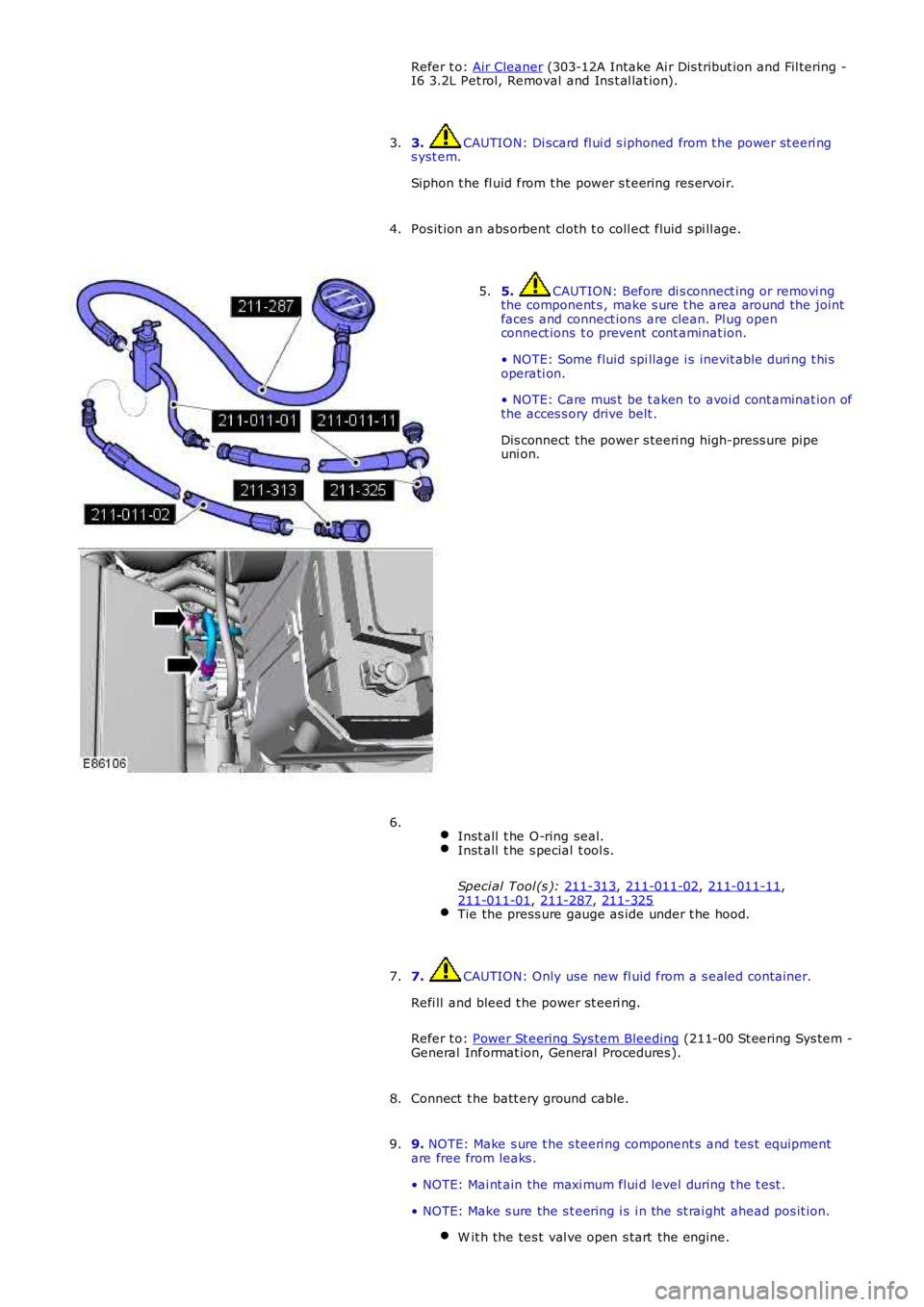
Refer t o:
Air Cleaner (303-12A Intake Ai r Dis tribut ion and Fil tering -
I6 3.2L Pet rol, Removal and Ins t al lat ion).
3. CAUTION: Di scard fl ui d s iphoned from t he power st eeri ng
s yst em.
Siphon t he fl uid from t he power s t eering res ervoi r.
3.
Pos it ion an abs orbent cl oth t o coll ect fluid s pi ll age.
4. 5. CAUTION: Before di s connect ing or removi ng
the component s , make s ure t he area around the joint
faces and connect ions are clean. Pl ug open
connect ions t o prevent cont aminat ion.
• NOTE: Some fluid spi llage i s inevit able duri ng t hi s
operati on.
• NOTE: Care mus t be t aken to avoi d cont aminat ion of
the acces s ory drive belt .
Dis connect the power s teeri ng high-press ure pipe
uni on.
5.
Inst all t he O-ring seal. Inst all t he s pecial t ool s.
Speci al Tool (s ): 211-313 ,
211-011-02 ,
211-011-11 ,
211-011-01 ,
211-287 ,
211-325 Tie the press ure gauge as ide under t he hood.6.
7. CAUTION: Only use new fl uid from a s ealed container.
Refi ll and bleed t he power st eeri ng.
Refer t o: Power St eering Sys tem Bleeding (211-00 St eering Sys tem -
General Informat ion, General Procedures ).
7.
Connect t he batt ery ground cable.
8.
9. NOTE: Make s ure t he s teeri ng component s and tes t equipment
are free from leaks .
• NOTE: Mai nt ain the maxi mum flui d level during t he t est .
• NOTE: Make s ure the s t eering i s i n the st rai ght ahead pos it ion. W it h the tes t val ve open s tart the engine. 9.
Page 552 of 3229
Turn the s t eering full y lock-t o-l ock, s top t he engine.
Top-up t he power st eeri ng fl uid reservoi r.
For power s t eering press ures , refer to the s t eering s peci fi cat ion
s ect ion.
Refer t o: Specificati ons (211-02 Power Steering, Specificati ons ).
10.
11. CAUTION: Do not hold st eering at full l ock for longer t han
10 s econds .
W it h the engi ne at idle, s lowl y turn t he s teeri ng wheel and
hold on full l ock. Record t he pres s ure readi ng.11.
Repeat t he above procedure for t he other s ide. Record t he pres s ure readi ng.12.
W it h the engi ne at idle, rel ease the s t eering wheel. The press ure
s houl d be, at or bel ow, the pres s ure specified.
13.
Pres s ure out si de t hi s t olerance, i ndicat es a fault .
14.
15. CAUTION: Pump damage wi ll occur if t he t est valve is
clos ed for l onger peri ods .
To det ermi ne if t he fault is i n t he st eeri ng pump or the st eeri ng
rack, clos e the tes t val ve for a maxi mum of 5 s econds.
15.
If the press ures recorded fal l out s ide t he given values, replace the
power st eeri ng pump.
16.
If the maxi mum pump pres sure i s correct, t hen s uspect the power
s teering rack.
17.
18. CAUTION: Dis card flui d s iphoned from t he power st eeri ng
s yst em.
On compl et ion of t he t est s t op the engi ne, dis connect t he bat t ery
ground cable and s i phon t he fluid from t he power st eering res ervoir.
18.
Di sas s emble t he t es t equipment .
19.
Clean t he component mat ing faces . Inst all a new O-ring s eal.
Connect t he high-press ure pipe union t o t he power st eeri ng
pump. T orque:
25 Nm 20.
Inst all t he air cleaner hous ing.
Refer t o: Air Cleaner (303-12A Intake Ai r Dis tribut ion and Fil tering -
I6 3.2L Pet rol, Removal and Ins t al lat ion).
21.
Connect t he batt ery ground cable.
Refer t o: Specificati ons (414-00 Bat tery and Charging Sys tem -
General Informat ion, Specificati ons).
22.
Page 585 of 3229

Publi s hed: 11-May-2011
Steering Column Switches - Steering Column Switches
Des cript ion and Operat ion
COMPONENT LOCATION
ItemPart NumberDescription
1-Speed cont rol s wit ches2-St eering column cas e containi ng the mult ifunct ion s wit ches and cl ocks pring
3-Audio control swit ches
OVERVIEW
The winds hield wiper s wit ch is l ocat ed in the right -hand-s ide of t he cas e and retai ned wit h 2 s crews . The s wit ch isconnected t o t he mai n harness vi a a connect or at the back of the s wi tch. The s wit ch cont rols the followi ng functi ons :
W i nds hiel d wi per i nt ermit tent s low and fas t speedW i nds hiel d wi per fli ck wipeW i nds hiel d was h/wi peRear was h/wipeInt ermit tent delay s electi on.
The t urn s ignal indicator s wit ch is locat ed i n t he left -hand-si de of the cas e and ret ained wi th 2 s crews . The swi tch i sconnected t o t he mai n harness vi a a connect or on the back of t he swit ch. The s wit ch cont rol s the foll owing funct ions:
Left / right turn s ignal operati onHigh / low beam operati onHeadl amp flas hTri p comput er functi on s el ect ion (i f fit t ed).
The t rip but t on allows the driver to cycle t hough an opti on menu and als o reset t ri p cycl e mi leage cal cul ati ons . The t ripcomput er informat ion i s dis played in the i nst rument clus ter mes s age cent er (high line ins trument cl us t er onl y).
Steering wheel mount ed s wit ches on the right -hand-s ide of t he dri ver's ai rbag, cont rol the audi o and tel ephone funct ions.Swit ches on the l eft -hand-s ide of t he dri ver's ai rbag control t he s peed cont rol functi ons .
The clocks pri ng is locat ed i n the front of t he cas e and retai ned wit h four s crews . The clocks pri ng engages i n s lots in t hes teeri ng wheel bos s and t urns wi th the rotat ion of t he s teeri ng wheel. The clocks pring incorporat es a t ang which cancelst he turn s ignal indicators when the st eering wheel i s rot ated.For addit ional informat ion, refer t o: Air Bag and Safet y Belt Pretens ioner Supplement al Res traint Syst em (SRS) (501-20BSuppl ement al Rest rai nt Sys tem, Des cri pti on and Operati on).
CONTROL DIAGRAM
• NOTE: A = Hardwi red; D = Hi gh s peed CAN bus , O = LIN bus
Page 1104 of 3229
25-Fuel fired heat er (i f fi tt ed)
26-Auxili ary coolant pump **
* Vehicles wit hout fuel fired heat er.
** Vehicles wi th fuel fi red heater.
INTELLIGENT TECHNOLOGY
New and revi s ed components as di s cus s ed in this secti on have been developed t o ensure t hat al l vehicl e s ys t ems operatevirtuall y uninterrupt ed in a Stop/St art cycl e.
Voltage Quality Module
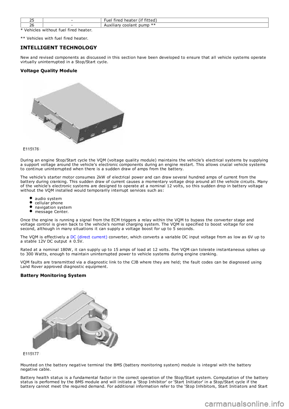
Duri ng an engine St op/Start cycle t he VQM (volt age qual it y module) mai ntains t he vehicle’s el ect ri cal s yst ems by s upplyinga s upport volt age around the vehicle's electroni c components during an engine res tart. This al lows crucial vehicle s ys temst o cont inue unint errupt ed when t here i s a s udden draw of amps from the bat tery.
The vehi cl e’s s t art er mot or cons umes 2kW of el ect ri cal power and can draw s everal hundred amps of current from thebatt ery during cranking. Thi s s udden draw of current causes a momentary volt age drop around al l t he vehicle ci rcuit s. Manyof the vehicle's electroni c s ys t ems are des i gned t o operat e at a nomi nal 12 volt s , so thi s s udden drop in bat tery volt agewit hout the VQM ins t al led woul d temporaril y i nt errupt servi ces such as :
audi o s yst emcel lul ar phonenavi gat ion sys temmes s age Cent er.
Once the engi ne is runni ng a s ignal from t he ECM triggers a relay wit hi n t he VQM t o bypass the converter s t age andvolt age control is gi ven back t o t he vehi cl e's normal charging sys tem. The VQM is specified t o boost vol tage for ones econd, alt hough i n many s it uati ons i t can s upply a volt age boos t for up t o 5 seconds .
The VQM is effecti vel y a DC (direct current) converter, which convert s a variable DC input vol tage from as l ow as 6V up t oa s t abl e 12V DC out put ± 0.5V.
Rated at a nominal 180W , it can s uppl y up t o 15 amps of load at 12 vol ts . The VQM can t olerat e i ns t ant aneous s pikes upt o 300 W at ts , enough to maintai n uninterrupt ed power t o vehicle s ys tems during engine cranking.
VQM fault s are trans mi tt ed via a diagnost ic l ink t o t he CJB where they are hel d; the fault codes can be di agnos ed us ingLand Rover approved diagnos t ic equipment .
Battery Monitoring System
Mounted on t he batt ery negat ive t ermi nal t he BMS (batt ery moni toring s yst em) module is i ntegral wi th t he batt erynegat ive cable.
Batt ery healt h s t at us i s a fundamental fact or in t he correct operat ion of t he Stop/St art s ys tem. Computat ion of t he batt erys tat us is performed by t he BMS module and will i nit iate a ‘St op Inhi bit or’ or ‘Start Ini ti at or’ i n a St op/Start cycle if t hebatt ery cannot meet t he requi red demand. For addit ional informati on refer to the ‘Stop Inhi bit ors , Start Init iat ors and St art