Page 1888 of 3229
1-Microphone
2-Telephone control modul e
3-Audi o ampl ifi er4-Speakers
5-Steeri ng wheel mount ed call s wit ches
6-Steeri ng wheel mount ed audio control s wi tches7-Clocks pring
8-Infotainment control modul e (ICM)
9-Int egrated audi o module (IAM)
Page 1892 of 3229

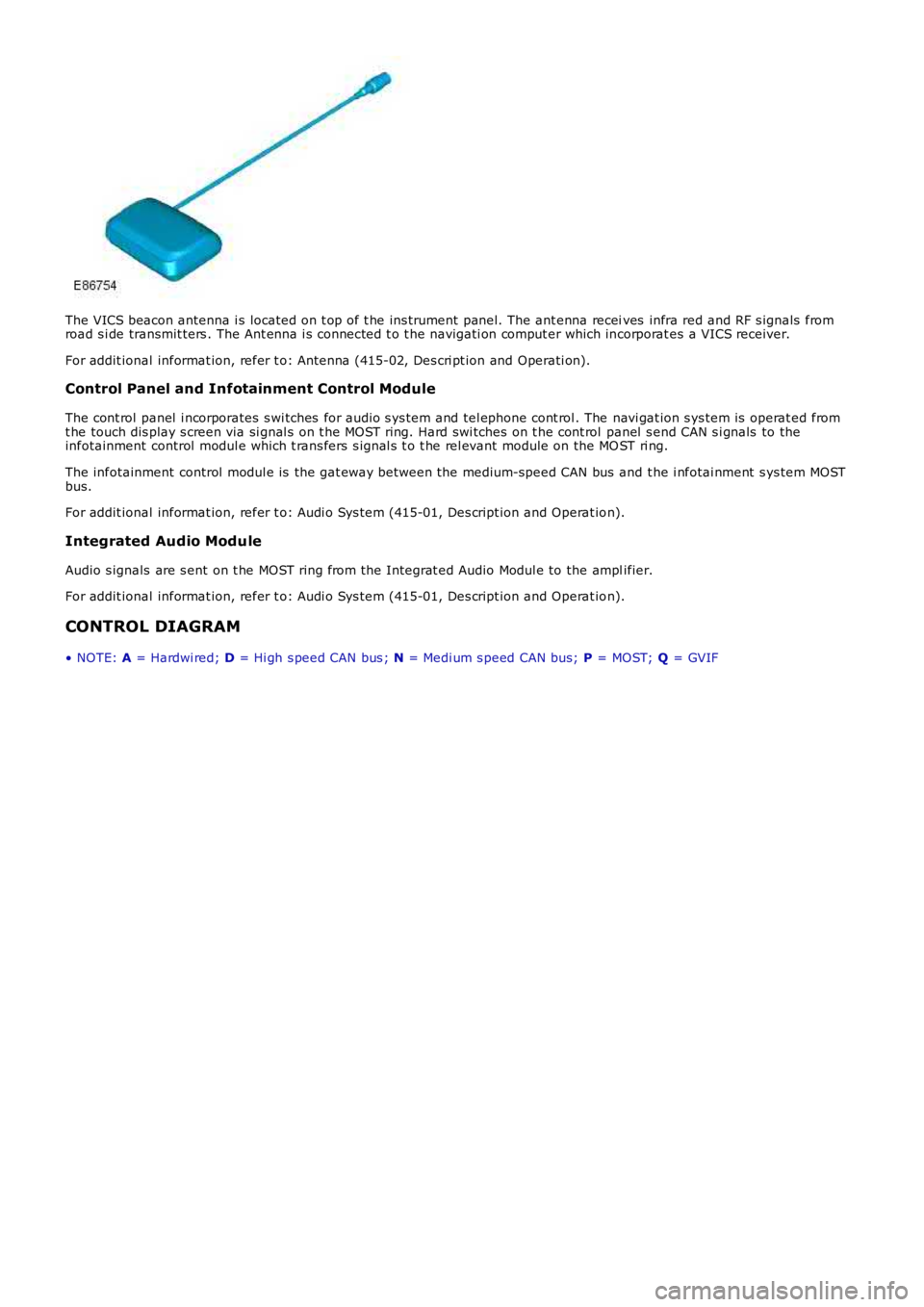
The VICS beacon antenna i s located on t op of t he ins trument panel. The ant enna receives infra red and RF s ignals fromroad s i de transmit ters . The Ant enna i s connected t o t he navigati on comput er which incorporat es a VICS receiver.
For addit ional informat ion, refer t o: Antenna (415-02, Des cri pt ion and Operati on).
Control Panel and Infotainment Control Module
The cont rol panel i ncorporates s wi tches for audio s ys tem and tel ephone cont rol . The navi gat ion s ys tem is operat ed fromt he touch dis play s creen via si gnal s on t he MOST ring. Hard swi tches on t he cont rol panel s end CAN s i gnals to theinfotainment control modul e which t rans fers s ignal s t o t he rel evant module on the MOST ri ng.
The infotainment control modul e is the gat eway bet ween the medium-speed CAN bus and t he i nfotai nment s ys tem MOSTbus.
For addit ional informat ion, refer t o: Audi o Sys tem (415-01, Des cript ion and Operat ion).
Integrated Audio Module
Audio s ignals are s ent on t he MOST ring from the Integrat ed Audio Modul e to the amplifier.
For addit ional informat ion, refer t o: Audi o Sys tem (415-01, Des cript ion and Operat ion).
CONTROL DIAGRAM
• NOTE: A = Hardwi red; D = Hi gh s peed CAN bus ; N = Medi um s peed CAN bus; P = MOST; Q = GVIF
Page 1905 of 3229
Publi s hed: 11-May-2011
Information and Entertainment System - Cellular Phone Antenna
Removal and Inst all ati on
Removal
• NOTE: Removal s t eps in t his procedure may cont ain i nst all ati on det ail s.
Remove both D-pil lar upper t rim panels .
Refer t o: D-Pi llar Trim Panel (501-05 Int eri or Trim and
Ornament ati on, Removal and Ins tal lat ion).
1. Releas e t he rear of the headli ner.
2. T orque:
10 Nm 3.
Installation To i nst all , revers e t he removal procedure.
1.
Page 1910 of 3229
Publi s hed: 11-May-2011
Antenna -
Torque SpecificationsDescriptionNmlb-ft
Audio uni t ant enna107
Cell ular phone ant enna107
Page 1912 of 3229
Digi tal Audio Broadcast ing (DAB) s yst em ant enna (s ide screen or roof pod mount ed depending on sys t em)
The AM/FM antenna is et ched ont o t he RH s i de window gl as s . The antenna has an ampli fi er locat ed jus t above thewindow. This ampl ifier wil l vary upon the ent ert ainment and informat ion s yst em fi tt ed to the vehicle. Hi gh li ne s ys t emswil l have a larger ampl ifier for divers i ty t uning.
The rear wi ndow incorporat es 2 FM ant ennae and a VICS/TMC ant enna etched onto t he glas s . The 2 FM ant ennae are us edin the di vers it y tuning sys tem along wi th the res pecti ve antenna ampli fi ers .
The LH s ide window antenna i s used for DAB band III s i gnal recepti on.
• NOTE: The t el ephone control modul e incorporat es a Bl uet ooth ant enna. This i s int egral to the modul e and as s uch is nots erviceabl e.
CONTROL DIAGRAM
• NOTE: A = Hardwi red; P = MOST; T = CoAxial
Page 1968 of 3229
6-El ect ronic rear different ial cont rol module
7-TCM
8-Headlamp leveling cont rol module9-Terrain Res ponse cont rol module
10-Ant i-lock Brake Sys tem (ABS) module
11-ECM - TD412-ECM - i6
CONTROL DIAGRAM - MOST
• NOTE: P = MOST
ItemPartNumberDescription
1-Int egrated control modul e
2-Int egrated head unit3-High Definati on (HD) radio modul e (NAS onl y from 2009MY )
4-Digit al Audi o Broadcas t (DAB) receiver / Sat ell it e Digi tal Audi o Radio Syt em (SDARS) (NAS only from2009MY ) receiver5-Bluetooth tel ephone module
6-Amplifier
7-Sat ell it e navi gat ion comput er8-Touch Screen Di spl ay (TSD)
Page 2018 of 3229

Ironst one W ay
Bri xwort h
Nort hant s
NN6 9UD
Unit ed Kingdom
Telephone: +44 (0) 1327 704461
Fax: +44 (0) 1327 706632
Repair Methods
CAUTION: Several different types and sizes of terminal may be found in a single electrical connector housing.
It is neces s ary to i dent ify:
The conductor (wire) si ze of the affected wiri ng harnes sThe electrical connect or range from which t he damaged wiri ng harnes s is to be removedThe t ermi nal t ype
Us e of the approved di agnos ti c tool wi ll greatl y as si s t in t he quick i dent ificati on of el ect ri cal connectors and faul ty pi nt ermi nal (s ).
Reference can als o be made to the vehicle Elect rical Gui des , held by Deal ers , to identi fy wi ri ng harness (s ) and el ect ri calconnector(s ).
By us ing t he Relat ionshi p Table, the wiring harnes s conductor (wire) si ze can be relat ed t o a s uit able pre-t ermi nat edwiring harnes s by t he color of the ins ul ati on. Al so, t he correct lengt h of ins ulati on t o be s tripped from the wiri ng harnes slead i s ident ifi ed.
Relationship Table
CABLE RANGESPLICEST RIP LENGT H
0.35 mm² t o 1.50 mm²RED6.00 t o 7.00 mm1.00 mm² t o 2.50 mm²BLUE6.00 t o 7.00 mm
4.00 mm² t o 6.00 mm²Y ELLO W9.00 t o 9.50 mm
Electrical Connector Terminal Extraction
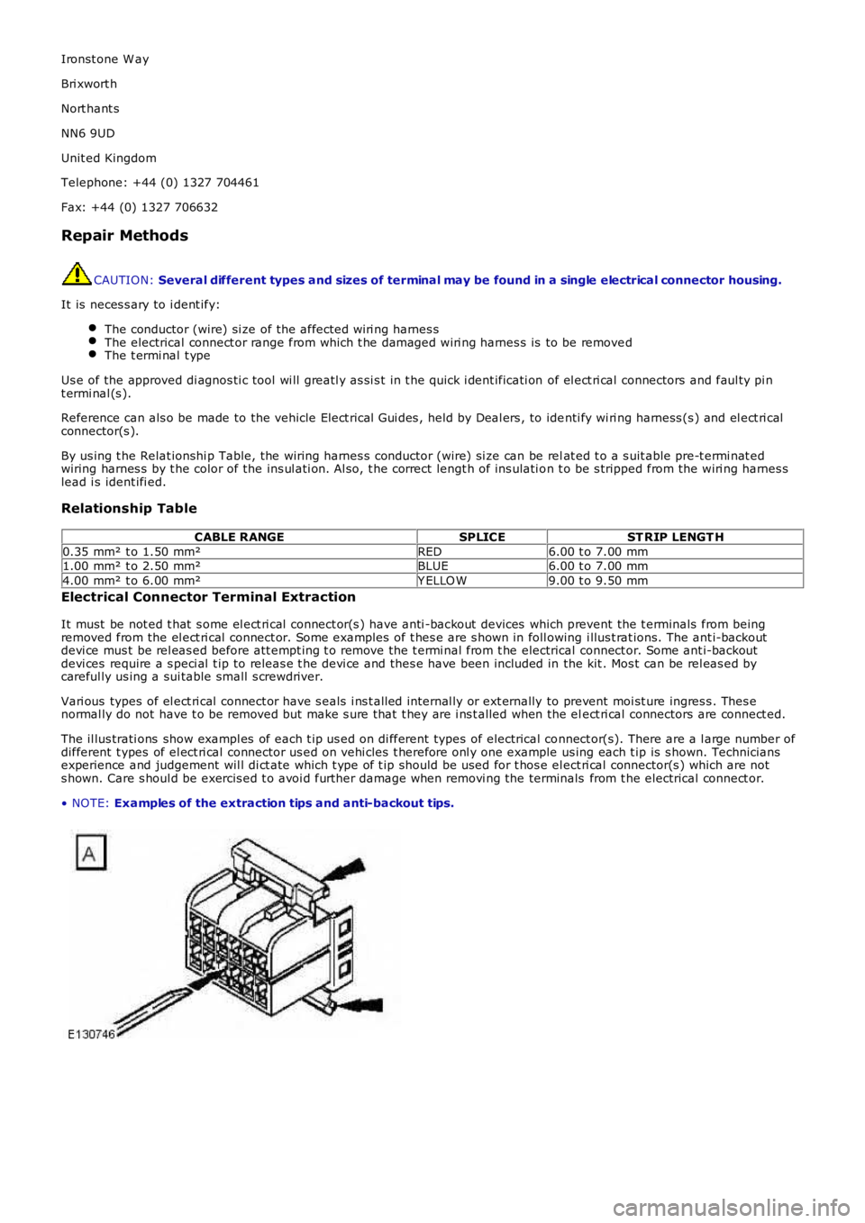
It must be not ed t hat s ome el ect ri cal connect or(s ) have anti -backout devices which prevent the t erminals from beingremoved from the el ect ri cal connect or. Some examples of t hes e are s hown in foll owing i llus t rat ions. The ant i-backoutdevi ce mus t be rel eas ed before att empt ing t o remove the t ermi nal from t he electrical connect or. Some ant i-backoutdevi ces require a s peci al t ip to releas e t he devi ce and thes e have been included in the kit . Mos t can be rel eas ed bycareful ly us ing a sui table small s crewdriver.
Vari ous types of el ect ri cal connect or have s eals i ns t alled internal ly or ext ernally to prevent moi st ure ingres s . Thes enormal ly do not have t o be removed but make s ure that t hey are i ns t alled when the elect ri cal connectors are connect ed.
The il lus trati ons show exampl es of each t ip us ed on di fferent types of electrical connect or(s). There are a l arge number ofdifferent t ypes of el ect ri cal connector us ed on vehi cles t herefore onl y one example us ing each t ip is s hown. Techniciansexperience and judgement wil l di ct ate which t ype of t ip should be used for t hos e el ect ri cal connector(s ) which are nots hown. Care s houl d be exercis ed t o avoi d further damage when removi ng the terminals from t he electrical connect or.
• NOTE: Examples of the extraction tips and anti-backout tips.
Page 2064 of 3229
Publi s hed: 11-May-2011
Multifunction Electronic Modules -
Torque SpecificationsDescriptionNmlb-ft
Cell ular phone ant enna Torx s crew107
Front door modul e11Rear door module11