2006 LAND ROVER FRELANDER 2 oil level
[x] Cancel search: oil levelPage 1197 of 3229
5-Cams haft Profi le Swi tching (CPS) sol enoid - rear
6-Pl enum variabl e int ake manifol d valve
7-Intake t ract vari abl e int ake manifol d valve8-Engine Cool ant Temperat ure (ECT) sens or
9-Engine oi l level/temperat ure s ens or
10-Engine Cont rol Module (ECM)11-Cams haft Pos it ion (CMP) s ens or (2 off)
12-Fuel rai l t emperat ure/press ure s ens or
13-Knock s ens ors (2 off)14-Cranks haft Pos it ion (CKP) sens or
15-El ect ri c thrott le
16-Purge val ve17-Mani fold Abs olut e Pres s ure (MAP) s ens or
18-Injectors (6 off)
19-CPS sol enoid - Front20-Ignit ion coil (6 off)
21-HO 2S Pos t -catal ys t
22-HO 2S Pos t -catal ys t
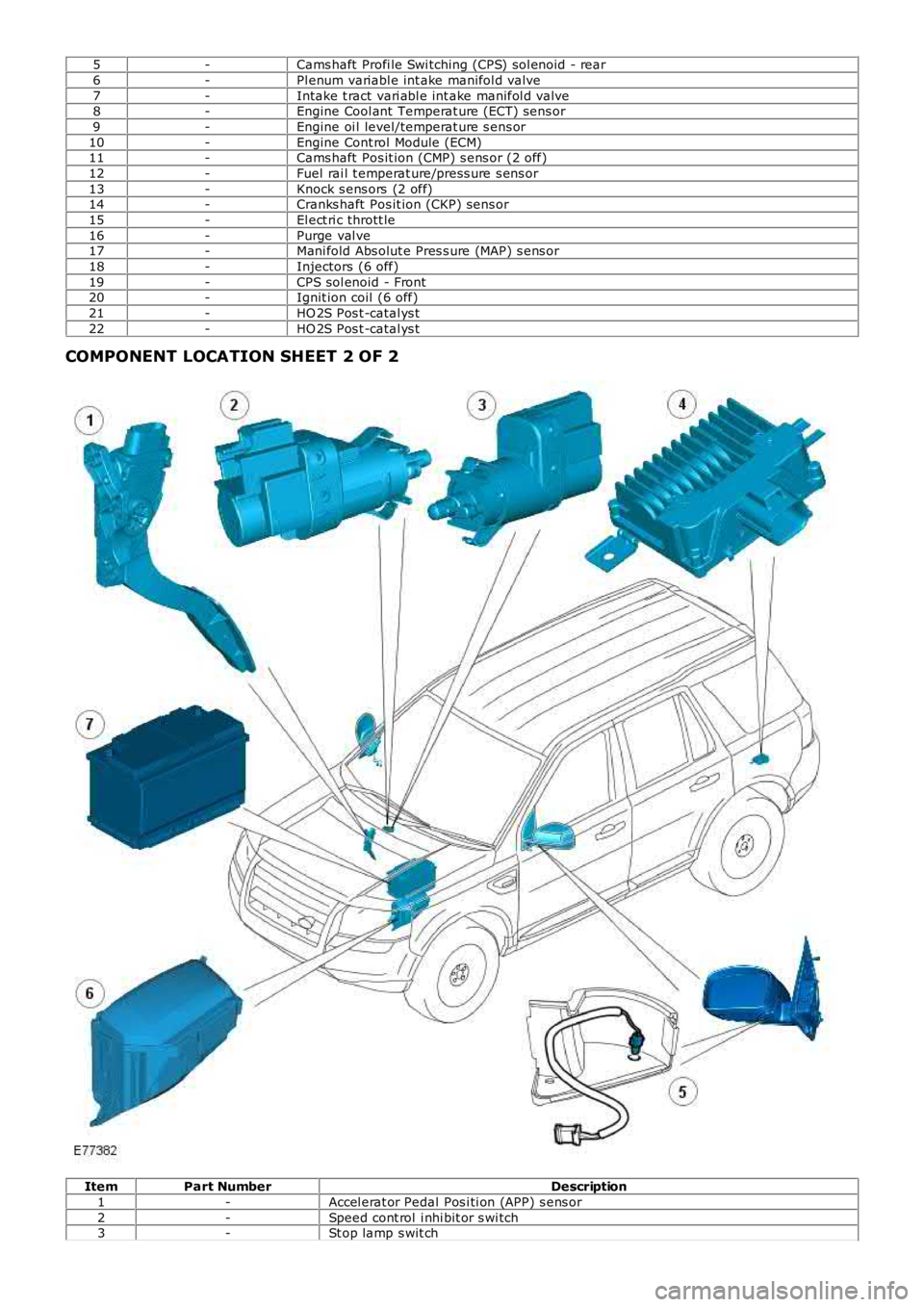
COMPONENT LOCATION SHEET 2 OF 2
ItemPart NumberDescription
1-Accel erat or Pedal Pos i ti on (APP) s ens or
2-Speed cont rol i nhi bit or s wi tch3-St op lamp s wit ch
Page 1206 of 3229
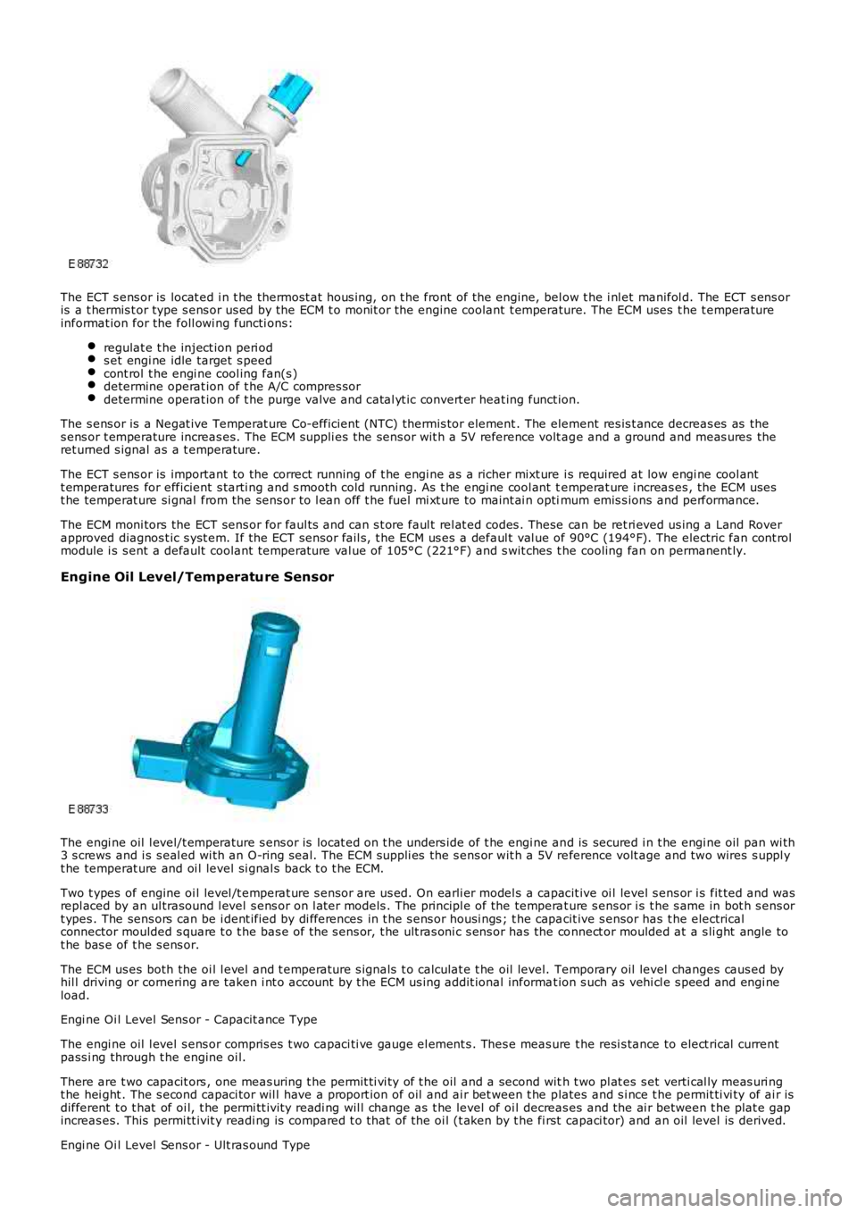
The ECT s ens or is locat ed i n t he thermost at hous ing, on t he front of the engine, below t he i nl et manifol d. The ECT s ens oris a t hermis t or type s ens or us ed by the ECM t o monit or the engine coolant t emperature. The ECM uses t he t emperatureinformat ion for the foll owi ng functi ons:
regulat e t he inject ion peri ods et engi ne idle target s peedcont rol t he engi ne cool ing fan(s )determine operat ion of t he A/C compres sordetermine operat ion of t he purge valve and catal yt ic convert er heat ing funct ion.
The s ens or is a Negat ive Temperat ure Co-efficient (NTC) thermis tor element . The element res is t ance decreas es as thes ens or t emperature increas es. The ECM suppli es the sens or wit h a 5V reference volt age and a ground and meas ures theret urned s ignal as a t emperature.
The ECT s ens or is important to the correct running of t he engi ne as a richer mixt ure i s required at low engi ne cool antt emperatures for efficient s tarti ng and s mooth cold running. As t he engi ne cool ant temperat ure i ncreas es , the ECM usest he temperat ure si gnal from the sens or to l ean off t he fuel mi xt ure to maint ai n optimum emis s ions and performance.
The ECM moni tors the ECT sens or for faul ts and can s t ore faul t rel at ed codes . These can be ret ri eved us ing a Land Roverapproved diagnos t ic s yst em. If the ECT sens or fail s, t he ECM us es a defaul t val ue of 90°C (194°F). The electric fan cont rolmodule i s s ent a default coolant temperat ure val ue of 105°C (221°F) and s wit ches t he cooling fan on permanent ly.
Engine Oil Level/Temperature Sensor
The engi ne oil l evel/t emperature s ens or is locat ed on t he unders ide of t he engi ne and is secured i n t he engi ne oil pan wi th3 s crews and i s s eal ed wi th an O-ring s eal. The ECM suppli es the s ens or wit h a 5V reference volt age and two wires s uppl yt he temperat ure and oi l level si gnal s back t o t he ECM.
Two t ypes of engine oi l level /t emperat ure s ensor are us ed. On earli er model s a capacit ive oi l level s ens or i s fit ted and wasrepl aced by an ul trasound l evel s ens or on l at er models . The principl e of the temperat ure s ens or i s t he s ame in bot h s ens ort ypes . The sens ors can be i dent ified by di fferences in t he s ens or housi ngs ; t he capacit ive s ensor has t he electricalconnector moulded s quare t o t he bas e of the s ens or, t he ult ras oni c s ens or has the connect or moulded at a s li ght angle tot he bas e of t he s ens or.
The ECM us es both the oi l l evel and t emperature s ignals t o calculat e t he oil level. Temporary oil level changes caus ed byhil l driving or cornering are taken i nt o account by t he ECM us ing addit ional informat ion s uch as vehi cl e s peed and engi neload.
Engi ne Oi l Level Sens or - Capacit ance Type
The engi ne oil l evel s ens or compris es t wo capaci ti ve gauge el ement s . Thes e meas ure the resi s tance to elect rical currentpass i ng through t he engine oi l.
There are t wo capacit ors , one meas uring t he permit ti vi ty of t he oil and a second with t wo pl at es s et verti cal ly meas uri ngt he hei ght . The s econd capaci tor wil l have a proport ion of oil and ai r bet ween t he plates and s i nce t he permit ti vi ty of ai r isdifferent t o t hat of oi l, t he permi tt ivit y readi ng wil l change as t he level of oi l decreas es and the ai r between t he plat e gapincreas es. This permi tt ivit y readi ng is compared t o t hat of the oi l (t aken by t he first capaci tor) and an oil level is derived.
Engi ne Oi l Level Sens or - Ult ras ound Type
Page 1207 of 3229
The engi ne oil l evel s ens or us es an ult ras oni c puls e, which is refl ect ed back from the s urface of t he oil . The ti me i t takesfor t his s i gnal t o ret urn t o t he s ensor i s turned int o a PW M s ignal and is s ent to the ECM. The ECM det ermi nes the ti met aken for the ul trasonic pul se si gnal t o be recei ved and calculat es it i nto an oil level fi gure.
Engi ne Oi l Temperat ure Sens or
The engi ne oil t emperature s ensor i s a Pos it ive Temperat ure Co-effi ci ent (PTC) thermis t or el ement . The element res i st anceincreas es as t he sens or temperat ure decreas es. The ECM s uppli es t he sens or wit h a 5V reference vol tage and a ground andmeas ures t he ret urned s ignal as a t emperature. A low oil temperature wil l res ult in a l ow volt age bei ng ret urned t o t heECM and hi gh oil temperature wil l ret urn a hi gh volt age reading.
The ECM moni tors the engine oi l level/temperat ure sens or for fault s and can s tore faul t rel at ed codes . These can beret ri eved us i ng a Land Rover approved diagnos t ic s ys tem. If the sens or fail s , the ECM us es t he engine cool ant temperat ures ens or s ignal val ue as a s ubst it ute.
Manifold Absolute Pressure (MAP) Sensor
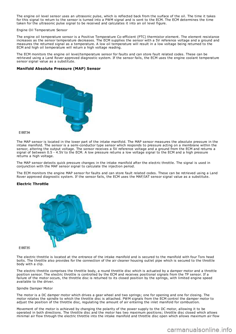
The MAP s ensor i s located i n t he lower part of t he int ake manifol d. The MAP s ens or meas ures t he abs olut e pres s ure in t heint ake manifol d. The sens or is a semi -conduct or type s ens or which responds t o pres s ure acti ng on a membrane wi thin thes ens or, al tering t he output volt age. The s ens or receives a 5V reference vol tage and a ground from t he ECM and returns as ignal of bet ween 0.5 - 4.5V t o t he ECM. A low pres sure ret urns a low vol tage s ignal to the ECM and a high press ureret urns a hi gh volt age.
The MAP s ensor det ect s quick pres s ure changes i n t he int ake mani fol d aft er the el ectri c thrott le. The s ignal is us ed inconjunct ion wi th the MAF sens or si gnal t o calculate the injecti on peri od.
The ECM moni tors the engine MAP s ens or for faul ts and can st ore fault related codes. Thes e can be ret ri eved us i ng a LandRover approved diagnost ic sys tem. If t he s ens or fai ls , the ECM uses t he MAF/IAT s ensor s i gnal value as a subs ti tut e.
Electric Throttle
The electric t hrot tl e is locat ed at t he entrance of t he int ake manifol d and is secured t o t he manifold wit h four Torx headbolt s. The t hrot tl e als o provi des for t he connect ion of t he air cleaner hous ing out let pipe which is secured t o t he t hrott lebody wit h a cl ip.
The electric t hrot tl e compri ses t he t hrott le body, a round throt t le di sc whi ch is act uat ed by a damper mot or and a thrott leposi ti on s ens or. The el ect ri c thrott le is control led by the ECM and recei ves pos i ti onal s ignals from the TP s ens or. If afai lure of the mot or occurs , t he thrott le di s c is returned to it s cl osed pos it ion by the s prings, wi th li mit ed engine s peedavai lable to the driver.
Spindle Damper Mot or
The mot or i s a DC damper motor which drives a gear wheel and t wo s pri ngs ; one for opening and one for cl osi ng. Themot or rotat es the spi ndl e t o which t he t hrott le dis c is at t ached. PW M s i gnals from the ECM control the damper mot or t oadjus t the pos it ion of t he t hrott le dis c, regul ati ng the amount of air ent ering the i nlet manifold for combus ti on.
Movement of t he mot or is achieved by changing t he polarit y of the power s uppl y to the DC mot or, all owing i t to beoperated in bot h direct ions . The throt tl e dis c and t he mot or has two maxi mum pos it ions ; t hrott le di s c cl osed which all owsmi ni mal air flow t hrough t he electric t hrot tl e int o t he int ake manifol d and t hrott le dis c open which all ows maximum air flow
Page 1209 of 3229
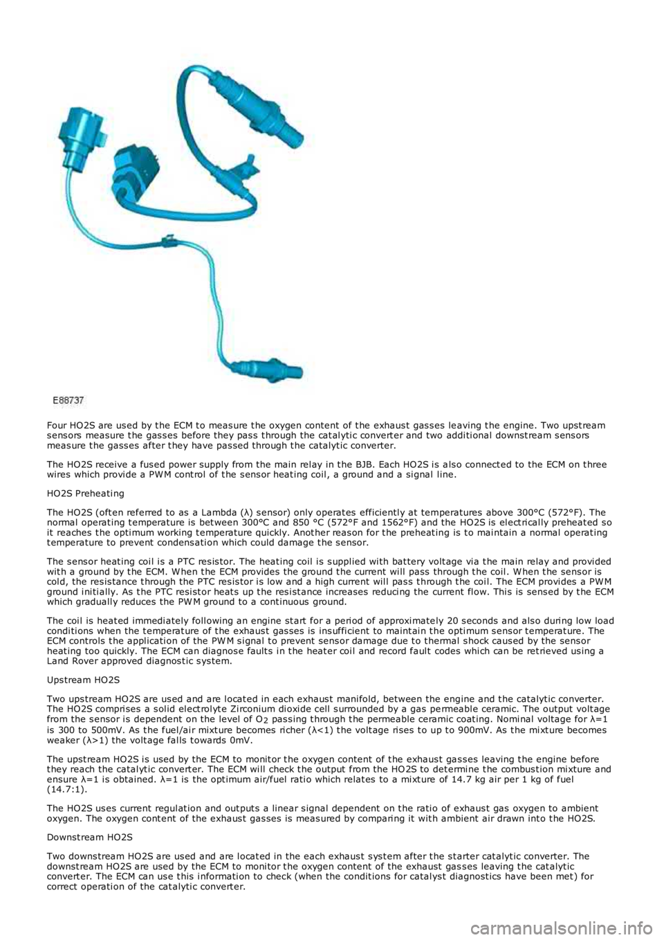
Four HO2S are us ed by t he ECM t o meas ure t he oxygen content of t he exhaus t gas s es leaving t he engine. Two upst reams ens ors measure t he gas s es before they pas s t hrough the cat al yti c convert er and two addi ti onal downst ream s ens orsmeas ure t he gass es after t hey have pas sed through t he catalyt ic converter.
The HO2S receive a fus ed power supply from t he main rel ay in t he BJB. Each HO2S i s als o connect ed to the ECM on t hreewires which provi de a PW M cont rol of t he s ens or heat ing coil , a ground and a si gnal l ine.
HO2S Preheati ng
The HO2S (oft en referred to as a Lambda (λ) s ensor) only operat es efficientl y at temperatures above 300°C (572°F). Thenormal operat ing t emperature is bet ween 300°C and 850 °C (572°F and 1562°F) and the HO2S is el ect ri cal ly preheat ed s oit reaches t he opti mum working t emperature quickly. Anot her reas on for t he preheat ing is t o mai ntain a normal operat ingt emperature to prevent condens ati on which could damage t he s ensor.
The s ens or heat ing coi l i s a PTC res is tor. The heat ing coil i s s uppl ied wi th bat tery volt age vi a t he main relay and provi dedwit h a ground by t he ECM. W hen t he ECM provides t he ground t he current wi ll pass through t he coil . W hen t he sens or iscol d, the res is tance t hrough the PTC res is tor i s low and a high current wil l pas s t hrough t he coi l. The ECM provi des a PW Mground i ni ti ally. As t he PTC resi st or heat s up t he res i st ance increases reduci ng the current fl ow. Thi s is sens ed by t he ECMwhich graduall y reduces the PW M ground to a cont inuous ground.
The coi l is heat ed immedi ately foll owing an engine st art for a peri od of approxi mately 20 s econds and als o duri ng low loadcondi ti ons when the t emperat ure of t he exhaus t gas s es is ins uffi cient to maint ai n t he opti mum s ens or t emperat ure. TheECM controls t he appl icati on of the PW M s i gnal t o prevent sens or damage due t o t hermal s hock caus ed by the sens orheat ing too quickly. The ECM can diagnos e fault s i n t he heat er coi l and record faul t codes whi ch can be ret rieved us ing aLand Rover approved diagnos t ic s ys tem.
Ups tream HO2S
Two ups tream HO2S are us ed and are l ocat ed in each exhaus t mani fold, between the engine and t he catalyt ic converter.The HO2S compri ses a s ol id el ect rol yt e Zi rconium di oxi de cel l s urrounded by a gas permeabl e ceramic. The output volt agefrom the s ensor i s dependent on the level of O2 pas s ing t hrough t he permeable ceramic coat ing. Nomi nal volt age for λ=1is 300 to 500mV. As t he fuel /ai r mixt ure becomes ri cher (λ<1) t he volt age ri ses t o up t o 900mV. As t he mi xt ure becomesweaker (λ>1) the volt age fal ls t owards 0mV.
The upst ream HO2S i s used by the ECM to monit or t he oxygen content of t he exhaus t gas s es leaving t he engine beforet hey reach the catal yt ic convert er. The ECM wi ll check t he output from the HO 2S to det ermi ne t he combus t ion mi xture andensure λ=1 i s obtained. λ=1 is the opt imum air/fuel rati o which relat es to a mi xt ure of 14.7 kg air per 1 kg of fuel(14.7:1).
The HO2S us es current regul at ion and out put s a linear s ignal dependent on t he rati o of exhaus t gas oxygen to ambientoxygen. The oxygen cont ent of the exhaus t gas ses is meas ured by compari ng it wit h ambient air drawn int o t he HO2S.
Downst ream HO2S
Two downs tream HO2S are us ed and are l ocat ed in the each exhaus t s ys t em after t he s tarter cat alyt ic converter. Thedownst ream HO2S are used by the ECM to moni tor t he oxygen content of the exhaust gass es leaving t he cat alyt icconvert er. The ECM can us e t his i nformati on to check (when the condit ions for catal ys t diagnost ics have been met ) forcorrect operati on of the cat alyti c convert er.
Page 1219 of 3229
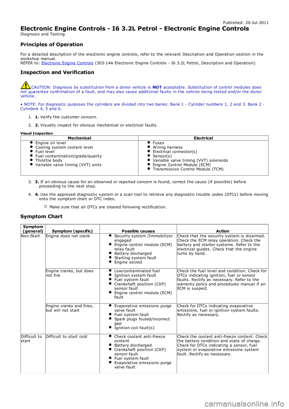
Publi shed: 20-Jul-2011
Electronic Engine Controls - I6 3.2L Petrol - Electronic Engine Controls
Diagnosi s and Tes ti ng
Principles of Operation
For a detail ed descripti on of the el ect ronic engi ne cont rols , refer to the relevant Des cri pti on and Operati on s ect ion i n t heworks hop manual .REFER to: Elect ronic Engine Cont rols (303-14A El ect ronic Engine Cont rols - I6 3.2L Petrol, Des cript ion and Operat ion).
Inspection and Verification
CAUTION: Di agnos is by s ubs ti tut ion from a donor vehicle is NO T acceptabl e. Subs ti tut ion of cont rol modules doesnot guarant ee confirmat ion of a faul t, and may als o caus e addit ional fault s i n t he vehi cl e being t est ed and/or t he donorvehi cl e.
• NOTE: For di agnos t ic purpos es the cyli nders are divided i nt o t wo banks: Bank 1 - Cyl inder numbers 1, 2 and 3. Bank 2 -Cylinders 4, 5 and 6.
1. Verify t he cus t omer concern.1.
2. Vis ually ins pect for obvious mechani cal or electrical fault s .2.
Visual Inspection
MechanicalElectricalEngine oil l evelCooli ng sys t em cool ant levelFuel l evelFuel contami nati on/grade/quali tyThrot tl e bodyVari abl e valve t iming (VVT) uni ts
Fus esW iring harnes sEl ect ri cal connector(s )Sens or(s)Variable val ve ti ming (VVT) s ol enoi dsEngine Cont rol Module (ECM)Trans mi s si on Control Module (TCM)
3. If an obvious cause for an obs erved or report ed concern is found, correct t he caus e (if pos s ible) beforeproceeding t o t he next s t ep.3.
4. Us e the approved di agnos ti c s ys t em or a s can t ool t o ret rieve any diagnos t ic t rouble codes (DTCs ) before movingont o t he sympt om chart or DTC i ndex.
Make s ure t hat all DTCs are cl eared fol lowing recti fi cat ion.
4.
Symptom Chart
Symptom(general)Symptom (specific)Possible causesActionNon-St artEngine does not crankSecuri ty s ys tem /Immobi lizerengagedEngine cont rol module (ECM)relay faultBat tery dis chargedSt art ing s ys tem faultEngine sei zed
Check t hat t he s ecurit y s ys t em i s dis armed.Check t he ECM rel ay operati on. Check t hebat tery and s tarter s yst ems . Refer to theel ect ri cal guides . Check t hat the engineturns by hand.
Engine cranks, but doesnot fi reLow/cont aminated fuelIgnit ion s ys tem faultFuel s ys t em faul tCranks haft pos it ion (CKP)sens or faultEngine cont rol module (ECM)fault
Check t he fuel level and condit ion. Check forDTCs indicati ng ignit ion, fuel or s ens orfault s. Recti fy as neces sary. Refer to t hewarrant y policy and procedures manual if anECM is sus pect .
Engine cranks and fi res ,but wil l not s t artEvaporat ive emi ss ions purgeval ve faultFuel s ys t em faul tSpark plugs foul ed/incorrectgapIgnit ion coil faul t(s )
Check for DTCs i ndi cat ing evaporat iveemis s ions, fuel or i gni ti on s ys t em fault s.Rect ify as neces sary.
Di fficul t t os tartDiffi cul t to s tart coldCheck cool ant ant i-freezecontentBat tery dis chargedCranks haft pos it ion (CKP)sens or faultFuel s ys t em faul tEvaporat ive emi ss ions purgeval ve fault
Check t he cool ant ant i-freeze content. Checkthe bat tery condit ion and s t ate of charge.Check for DTCs i ndi cat ing a s ens or, fuelsys tem or evaporat ive emi s si ons sys temfault . Rect ify as neces s ary.
Page 1237 of 3229
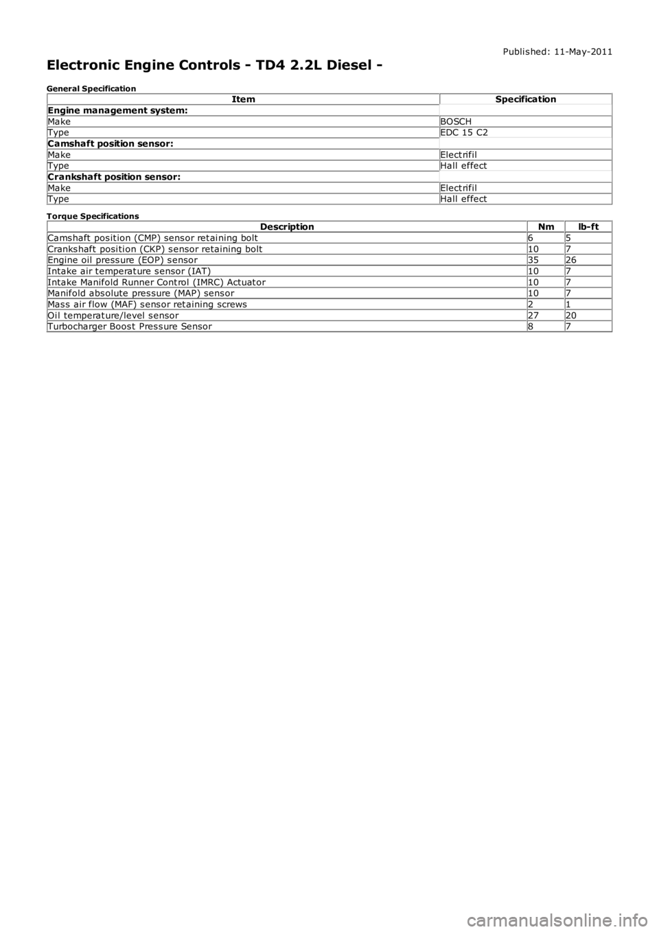
Publi s hed: 11-May-2011
Electronic Engine Controls - TD4 2.2L Diesel -
General SpecificationItemSpecification
Engine management system:
MakeBOSCHTypeEDC 15 C2
Camshaft position sensor:
MakeElect rifilTypeHall effect
Crankshaft position sensor:
MakeElect rifilTypeHall effect
Torque SpecificationsDescriptionNmlb-ft
Cams haft pos it ion (CMP) sens or ret ai ning bolt65
Cranks haft posi ti on (CKP) s ensor retaini ng bolt107Engine oil press ure (EOP) s ensor3526
Intake air t emperat ure s ensor (IAT)107
Intake Manifold Runner Cont rol (IMRC) Actuat or107Manifold abs olute pres sure (MAP) sens or107
Mas s air flow (MAF) s ens or ret aining screws21
Oi l temperat ure/level s ensor2720Turbocharger Boos t Pres s ure Sensor87
Page 1246 of 3229
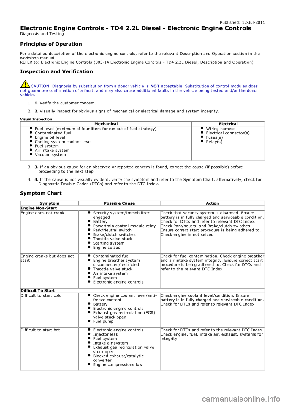
Publi shed: 12-Jul-2011
Electronic Engine Controls - TD4 2.2L Diesel - Electronic Engine Controls
Diagnosi s and Tes ti ng
Principles of Operation
For a detail ed descripti on of the el ect ronic engi ne cont rols , refer to the relevant Des cri pti on and Operati on s ect ion i n t heworks hop manual .REFER to: Elect ronic Engine Cont rols (303-14 El ect ronic Engine Cont rols - TD4 2.2L Di esel , Des cri pti on and Operati on).
Inspection and Verification
CAUTION: Di agnos is by s ubs ti tut ion from a donor vehicle is NO T acceptabl e. Subs ti tut ion of cont rol modules doesnot guarant ee confirmat ion of a faul t, and may als o caus e addit ional fault s i n t he vehi cl e being t est ed and/or t he donorvehi cl e.
1. Verify t he cus t omer concern.1.
2. Vis ually ins pect for obvious s igns of mechani cal or electrical damage and sys tem integrit y.2.
Visual InspectionMechanicalElectrical
Fuel l evel (mini mum of four lit ers for run out of fuel s t rategy)Contami nat ed fuelEngine oil l evelCooli ng sys t em cool ant levelFuel s ys temAir i ntake s yst emVacuum s ys t em
W i ri ng harnessElectrical connect or(s)Fus es (s )Relay(s )
3. If an obvious cause for an obs erved or report ed concern is found, correct t he caus e (if pos s ible) beforeproceeding t o t he next s t ep.3.
4. If t he caus e is not vis ually evi dent , verify t he sympt om and refer t o t he Sympt om Chart, al ternat ively, check forDi agnos ti c Trouble Codes (DTCs) and refer t o t he DTC Index.4.
Symptom Chart
SymptomPossible CauseAction
Engine Non-StartEngine does not crankSecurit y s yst em/Immobi li zerengagedBatt eryPowert rai n cont rol module relayPark/Neut ral s wit chBrake/cl ut ch s wit chesThrot tl e valve s tuckSt arti ng s yst emEngine s eized
Check t hat securi ty s ys tem is di sarmed. Ens urebat t ery i s in full y charged and s erviceabl e condi ti on.Check for DTCs and refer t o rel evant DTC Index.Check Park/neut ral and Brake/cl ut ch s wit ches .Ens ure correct s tart procedure is bei ng adhered to.Check engine i s not sei zed
Engine cranks but does nots tartContami nat ed fuelEngine breat her s ys temdis connected/res trictedThrot tl e valve s tuckAir i ntake s yst emFuel s ys temElectronic engine controls
Check for fuel cont aminati on. Check engi ne breat herand air int ake sys t em i nt egri ty. Ensure correct s tartprocedure is bei ng adhered to. Check for DTCs andrefer t o t he rel evant DTC Index
Difficult T o Start
Di fficul t t o s tart col dCheck engi ne coolant l evel/anti -freeze cont entBatt eryElectronic engine controlsExhaus t gas recircul ati on (EGR)valve s t uck openFuel pump
Check engine coolant level/condit ion. Ensurebat t ery i s in full y charged and s erviceabl e condi ti on.Check for DTCs and refer t o rel evant DTC Index
Di fficul t t o s tart hotElectronic engine controlsInjector leakFuel s ys temIntake air s ys temExhaus t gas recircul ati on val ves tuck openBlocked exhaus t/cat alyt icconverterEngine compres s ions low
Check for DTCs and refer t o t he rel evant DTC Index.Check engine, fuel, i ntake air, exhaus t, s ys tems forint egrit y
Page 1248 of 3229
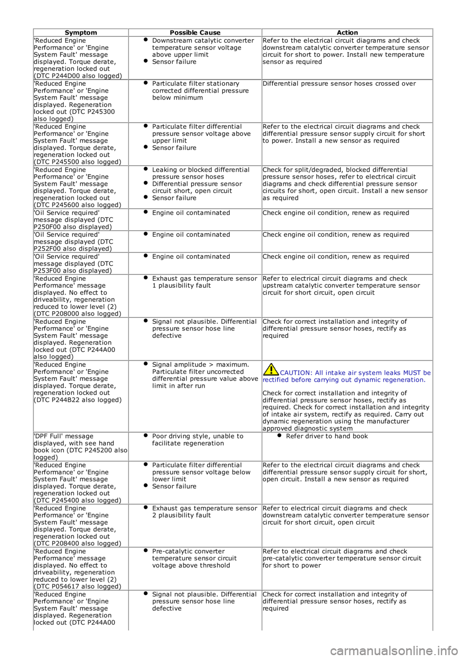
SymptomPossible CauseAction
'Reduced Engi nePerformance' or 'EngineSyst em Fault ' mes sagedis played. Torque derate,regenerat ion l ocked out(DTC P244D00 al so logged)
Downs tream catalyt ic convertert emperature s ens or volt ageabove upper li mi tSensor failure
Refer to the el ect ri cal circui t diagrams and checkdowns t ream cat al yti c convert er temperat ure sens orci rcuit for short to power. Ins tal l new temperat uresens or as required
'Reduced Engi nePerformance' or 'EngineSyst em Fault ' mes sagedis played. Regenerat ionl ocked out (DTC P245300als o l ogged)
Part iculat e fi lt er st ati onarycorrect ed different ial pres s urebelow mini mum
Different ial pres s ure s ensor hos es cross ed over
'Reduced Engi nePerformance' or 'EngineSyst em Fault ' mes sagedis played. Torque derate,regenerat ion l ocked out(DTC P245500 al so logged)
Part iculat e fi lt er different ialpres s ure s ens or volt age aboveupper l imitSensor failure
Refer to the el ect ri cal circui t diagrams and checkdifferent ial pres sure s ens or s uppl y circuit for s hortto power. Ins tal l a new s ensor as requi red
'Reduced Engi nePerformance' or 'EngineSyst em Fault ' mes sagedis played. Torque derate,regenerat ion l ocked out(DTC P245600 al so logged)
Leaki ng or blocked di fferenti alpres s ure s ens or hos esDi fferenti al pres s ure sens orcircui t short, open circui tSensor failure
Check for spl it /degraded, bl ocked different ialpres sure s ens or hoses , refer to el ect ri cal circui tdiagrams and check different ial pres sure s ens orci rcuit s for s hort , open ci rcuit . Ins t al l a new s ensoras required
'O il Service requi red'mes s age dis played (DTCP250F00 al so dis played)
Engine oil contami nat edCheck engine oi l condit ion, renew as requi red
'O il Service requi red'mes s age dis played (DTCP252F00 al so dis played)
Engine oil contami nat edCheck engine oi l condit ion, renew as requi red
'O il Service requi red'mes s age dis played (DTCP253F00 al so dis played)
Engine oil contami nat edCheck engine oi l condit ion, renew as requi red
'Reduced Engi nePerformance' mes s agedis played. No effect t odri veabi lit y, regenerati onreduced t o lower level (2)(DTC P208000 al so logged)
Exhaus t gas t emperature s ens or1 pl aus i bi li ty faultRefer to elect rical circui t diagrams and checkups t ream cat alyti c convert er temperat ure sens orci rcuit for short ci rcuit , open ci rcuit
'Reduced Engi nePerformance' or 'EngineSyst em Fault ' mes sagedis played. Regenerat ionl ocked out (DTC P244A00als o l ogged)
Signal not pl aus i bl e. Different ialpres s ure s ens or hos e l inedefecti ve
Check for correct ins tall ati on and int egrit y ofdifferent ial pres sure s ens or hoses , rect ify asrequired
'Reduced Engi nePerformance' or 'EngineSyst em Fault ' mes sagedis played. Torque derate,regenerat ion l ocked out(DTC P244B22 al so logged)
Signal ampli tude > maximum.Part iculat e fi lt er uncorrect eddifferent ial pres s ure value abovel imi t in after run
CAUTION: All i nt ake air s yst em leaks MUST berecti fi ed before carrying out dynamic regenerat ion.
Check for correct ins tall ati on and int egrit y ofdifferent ial pres sure s ens or hoses , rect ify asrequired. Check for correct i ns t allat ion and i ntegri tyof intake ai r sys tem, rect ify as requi red. Carry outdynami c regenerati on us ing t he manufacturerapproved di agnos ti c s ys t em'DPF Ful l' mes sagedis played, wit h s ee handbook icon (DTC P245200 al sol ogged)
Poor drivi ng st yle, unabl e t ofaci lit ate regenerati onRefer dri ver t o hand book
'Reduced Engi nePerformance' or 'EngineSyst em Fault ' mes sagedis played. Torque derate,regenerat ion l ocked out(DTC P245400 al so logged)
Part iculat e fi lt er different ialpres s ure s ens or volt age belowl ower l imi tSensor failure
Refer to the el ect ri cal circui t diagrams and checkdifferent ial pres sure s ens or s uppl y circuit for s hort,open ci rcuit . Ins tal l a new s ensor as requi red
'Reduced Engi nePerformance' or 'EngineSyst em Fault ' mes sagedis played. Torque derate,regenerat ion l ocked out(DTC P208400 al so logged)
Exhaus t gas t emperature s ens or2 pl aus i bi li ty faultRefer to elect rical circui t diagrams and checkdowns t ream cat al yti c convert er temperat ure sens orci rcuit for short ci rcuit , open ci rcuit
'Reduced Engi nePerformance' mes s agedis played. No effect t odri veabi lit y, regenerati onreduced t o lower level (2)(DTC P054617 al so logged)
Pre-cat alyt ic convertert emperature s ens or circui tvolt age above t hres hol d
Refer to elect rical circui t diagrams and checkpre-cat al yti c convert er temperat ure s ens or ci rcuitfor s hort t o power
'Reduced Engi nePerformance' or 'EngineSyst em Fault ' mes sagedis played. Regenerat ionl ocked out (DTC P244A00
Signal not pl aus i bl e. Different ialpres s ure s ens or hos e l inedefecti ve
Check for correct ins tall ati on and int egrit y ofdifferent ial pres sure s ens or hoses , rect ify asrequired