2006 LAND ROVER FRELANDER 2 oil level
[x] Cancel search: oil levelPage 775 of 3229
ItemPart NumberDescription
1-Oil fill er tube
2-Oil s eparator3-Oil t emperature s ens or
4-Oil s eparator ret urn pi pe
5-Oil pan housi ng bolt s (20 off)6-Oil pan housi ng
7-Oil level gage
The alumi num oil pan hous ing i s s ecured wit h 20 bolt s t o t he bot t om of t he cyl inder bl ock, and forms an ext ens ionbetween t he cyl inder block and oil pan. The oi l pan hous ing i s requi red i n order t o increas e t he dis tance between t he oilpump and oil pan, due to the ins tall ati on of the counter-balance s haft ass embly.
The rear of t he oil pan hous i ng provides t he lower mounti ng poi nts for the trans mi s si on cas i ng. Dril lings formed in t he LHs ide of t he hous i ng provide t he locati on for t he oil l evel gage tube, oil t emperature s ens or, and t he ret urn hos e from t hecrankcas e venti lati on oil s eparator.
The crankcas e venti lati on oil s eparator i s als o connected to t he oil fil ler t ube, located at t he rear LH si de of the engine. Oi lfor repl enis hing t he s ys t em pas ses through t he oil s eparator and return hos e, and int o t he oil pan. An oil baffle pl ate i sins t al led i n t he oil pan housi ng to reduce oil aerat ion and s plas h.
Oil Pump
The rot or type oil pump is l ocat ed bet ween t he oil pan and oil pan housi ng, and at t ached wi th 5 bol ts to the front of t hecount er-bal ance s haft as s embly. The oil pump i s dri ven by the cranks haft via a s ingle row chain. For furt her informati on,refer to 'Lubricati on Sys t em' wit hin t his s ecti on.
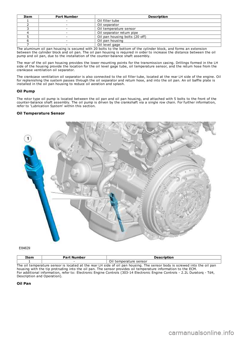
Oil Temperature Sensor
ItemPart NumberDescription1-Oil t emperature s ens or
The oil t emperature s ens or is locat ed at t he rear LH s ide of oi l pan hous ing. The s ens or body is s crewed i nto the oi l panhous i ng wit h t he t ip prot rudi ng int o t he oil pan. The s ens or provi des oi l temperat ure informati on t o t he ECM.For addit ional informat ion, refer t o: Electroni c Engi ne Controls (303-14 Electronic Engine Controls - 2.2L Durat orq - Td4,Des cript ion and Operat ion).
Oil Pan
Page 799 of 3229
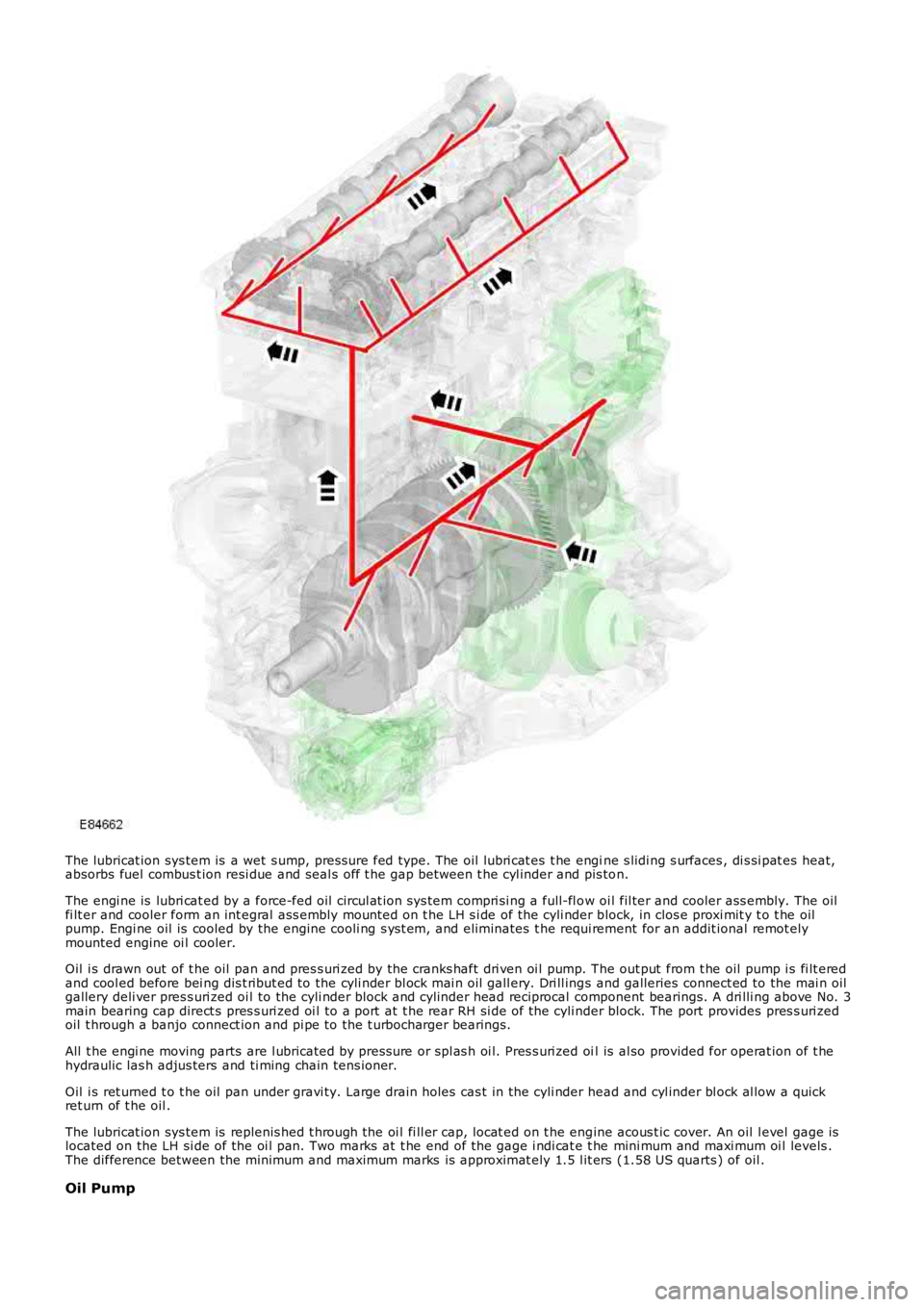
The lubricat ion sys tem is a wet s ump, pres sure fed type. The oil lubri cat es t he engine s lidi ng s urfaces , di s si pat es heat,absorbs fuel combus t ion resi due and seal s off t he gap between t he cyl inder and pis ton.
The engi ne is lubri cat ed by a force-fed oil circul at ion sys tem compri si ng a full-fl ow oi l fil ter and cooler ass embly. The oilfi lt er and cooler form an int egral ass embly mount ed on t he LH s i de of the cyli nder block, in clos e proxi mit y t o t he oilpump. Engi ne oil is cooled by the engine cooli ng s ys t em, and eliminates t he requi rement for an addit ional remot elymounted engine oi l cooler.
Oil i s drawn out of t he oil pan and pres s uri zed by the cranks haft dri ven oi l pump. The out put from t he oil pump i s fi lt eredand cool ed before bei ng dis t ribut ed to the cyli nder bl ock mai n oil gall ery. Dri ll ings and galleries connect ed to the mai n oilgallery deli ver pres s uri zed oi l to the cyli nder block and cyl inder head reciprocal component bearings. A dri lli ng above No. 3main bearing cap direct s pres s uri zed oi l to a port at t he rear RH si de of the cyli nder block. The port provides pres s uri zedoil t hrough a banjo connect ion and pi pe to the t urbocharger bearings.
All t he engi ne moving parts are l ubricated by press ure or spl as h oi l. Pres s uri zed oil is al so provided for operat ion of t hehydraulic las h adjus ters and ti ming chain tens ioner.
Oil i s ret urned t o t he oil pan under gravi ty. Large drain holes cas t in the cyli nder head and cyl inder bl ock al low a quickret urn of t he oil .
The lubricat ion sys tem is replenis hed t hrough the oi l fi ll er cap, locat ed on t he engine acous t ic cover. An oil l evel gage islocated on the LH si de of the oi l pan. Two marks at t he end of the gage i ndi cat e t he mini mum and maxi mum oi l levels .The difference between the minimum and maximum marks is approximat ely 1.5 l it ers (1.58 US quarts ) of oil .
Oil Pump
Page 800 of 3229
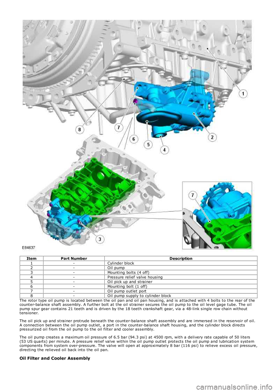
ItemPart NumberDescription
1-Cyl inder block2-Oil pump
3-Mount ing bol ts (4 off)
4-Pres sure rel ief valve housi ng5-Oil pick up and st rai ner
6-Mount ing bol t (1 off)
7-Oil pump out let port8-Oil pump s upply t o cyli nder block
The rot or type oil pump is l ocat ed bet ween t he oil pan and oil pan housi ng, and is at tached wit h 4 bol ts t o t he rear of t hecount er-bal ance s haft as s embly. A furt her bolt at t he oil s t rainer s ecures the oi l pump to the oi l level gage t ube. The oi lpump s pur gear cont ains 21 teeth and is driven by t he 18 t eet h cranks haft gear, via a 48-li nk s ingle row chain wi thoutt ens ioner.
The oil pick up and s t rai ner prot rude beneath the count er-balance shaft ass embly and are i mmersed i n t he res ervoir of oil .A connect ion between the oi l pump out let , a port i n t he count er-bal ance s haft hous ing, and the cyli nder block direct spres s urized oi l from t he oil pump t o t he oil filt er and cool er as s embly.
The oil pump creat es a maximum oi l press ure of 6.5 bar (94.3 ps i) at 4500 rpm, wit h a deli very rat e capabl e of 50 li ters(53 US quart s) per mi nut e. A pres s ure reli ef val ve wit hin t he oil pump out let prot ect s t he oil pump and l ubricati on s yst emcomponents from s ys tem over-pres s ure. The valve wi ll open at approxi matel y 8 bar (116 ps i) to reli eve excess oi l pres sure,direct ing t he rel ieved oil back int o t he oil pan.
Oil Filter and Cooler Assembly
Page 802 of 3229
Publi s hed: 11-May-2011
Engine - TD4 2.2L Diesel - Engine
Diagnosi s and Tes ti ng
Principle of Operation
For a detail ed descripti on of the 2.2L Dies el engi ne, refer t o the relevant Descri pti on and Operat ion s ect ion in t heworks hop manual .REFER to: Engine (303-01B Engine - TD4 2.2L Dies el, Des cript ion and Operat ion).
Inspection and Verification
CAUTION: Di agnos is by s ubs ti tut ion from a donor vehicle is NO T acceptabl e. Subs ti tut ion of cont rol modules doesnot guarant ee confirmat ion of a faul t, and may als o caus e addit ional fault s i n t he vehi cl e being t est ed and/or t he donorvehi cl e.
• NOTE: If the control modul e or a component i s s us pect and the vehicle remains under manufacturer warrant y, refer t o theW arranty Pol icy and Procedures manual (s ect ion B1.2), or determine i f any pri or approval programme is in operat ion, pri ort o the ins tall ati on of a new module/component.
1. Verify t he cus t omer concern. Concerns have been s eparated i nto Leaks and Noise Vibration and Harshness(NVH) for ease of us e.1.
2. Vis ually ins pect for obvious s igns of mechani cal or electrical damage.2.
Visual Inspection
MechanicalIntake air s ys tem leaks/damageFuel l eaksCoolant levelCoolant leaks.REFER to: Engine Cooli ng (303-03B Engi ne Cool ing - TD4 2.2L Di es el, Di agnos is and Tes t ing).Oi l levelOi l leaksVis i bl y damaged or worn partsLoose or mis s ing nuts or bol ts
3. If an obvious cause for an obs erved or report ed concern is found, correct t he caus e (if pos s ible) beforeproceeding t o t he next s t ep.3.
4. If t he concern is not vis uall y evi dent , verify t he s ymptom and refer t o t he Symptom Chart .4.
Symptom Charts
Symptom C hart, LeaksSymptomPossible CauseAction
External coolant leaksDamaged hos e(s )Damaged expans iont ankDamaged radi atorLeaki ngs eals /gas ket sCracked/damagedcas ings
For cool ing s ys tem checks.REFER t o: Engi ne Cool ing (303-03B Engine Cooli ng - TD42.2L Dies el, Di agnos is and Tes ti ng).
Internal cool ant leaks . Note: T hismay be indicated by theproduction of w hite smoke fromthe exhaust
Leaki ngs eals /gas ket sCracked/damagedcas ings
Check for cros s contami nat ion of cooli ng sys t em andengine oi l. Check for exhaus t gases bei ng emit tedt hrough header t ank. For addi ti onal cooling sys temchecks .REFER t o: Engi ne Cool ing (303-03B Engine Cooli ng - TD42.2L Dies el, Di agnos is and Tes ti ng).
Engine overheatsInsuffi ci ent coolantInsuffi ci ent engineoi lCooli ng s ys t empres s ure cap faultThermos t at notopeningCoolant pump failureCooli ng fan fail ure
Check for correct coolant/engi ne oil l evels . For cool ings ys tem checks.REFER t o: Engi ne Cool ing (303-03B Engine Cooli ng - TD42.2L Dies el, Di agnos is and Tes ti ng).
Engine t akes t oo l ong to reachoperat ing t emperatureThermos t at st uckopenFor cool ing s ys tem checks.REFER t o: Engi ne Cool ing (303-03B Engine Cooli ng - TD42.2L Dies el, Di agnos is and Tes ti ng).External oil l eaksGas ket sSealsHos esOi l fi lt erOi l coolerDamaged/Cracked
Cl ean and confirm t he area of t he l eak. Vis uall y check t hecondit ion of oil carryi ng component s. Check the crankcaseventi lat ion s ys tem.REFER t o: Engi ne Emis s ion Cont rol (303-08B EngineEmis si on Control - TD4 2.2L Di es el, Di agnos is andTes ti ng).
Page 803 of 3229
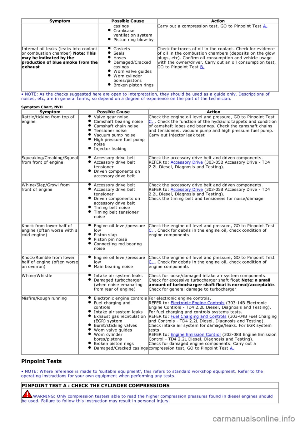
SymptomPossible CauseAction
cas ingsCrankcaseventi lat ion s yst emPi st on ring blow-by
Carry out a compres s ion tes t, GO to Pinpoint Test A.
Internal oil l eaks (leaks int o cool antor combus t ion chamber) Note: T hismay be indicated by theproduction of blue smoke from theexhaust
Gas ket sSealsHos esDamaged/Crackedcas ingsW orn valve gui desW orn cyli nderbores /pi s tonsBroken pi st on rings
Check for t races of oil in the coolant. Check for evidenceof oi l i n t he combus t ion chambers (depos it s on t he glowpl ugs , et c). Confirm oi l cons umpti on and vehi cl e us agewit h the owner/driver. Carry out an oil consumpt ion t es t,GO t o Pinpoint Test B.
• NOTE: As t he checks s ugges ted here are open to i nterpretat ion, they s hould be us ed as a gui de only. Descripti ons ofnois es, et c, are i n general t erms, s o depend on a degree of experi ence on t he part of t he t echnician.
Symptom C hart, NVHSymptomPossible CauseAction
Ratt le/ti cki ng from t op ofengineVal ve gear noi seCamshaft bearing nois eCamshaft chain noi s eTens ioner nois eVacuum pump noi s eHigh pres s ure fuel pumpnoi s eInject or leaki ng
Check t he engi ne oil l evel and pres s ure, GO t o Pi npoint Tes tC. . Check t he functi on of the hydrauli c t appet s and condit ionof cams haft l obes and beari ngs. Check the cams haft chainsand tens ioners , vacuum pump and high pres s ure fuel pump.Carry out i njector l eak t es t
Squeaking/Creaking/Squealfrom front of engineAcces sory dri ve bel tAcces sory dri ve bel ttens ionerDri ven component s onaccess ory dri ve bel t
Check t he acces sory dri ve belt and dri ven components .REFER t o: Acces s ory Drive (303-05B Acces sory Drive - TD42.2L Di es el, Di agnos is and Tes t ing).
W hi ne/Slap/Growl fromfront of engi neAcces sory dri ve bel tAcces sory dri ve bel ttens ionerDri ven component s onaccess ory dri ve bel tTimi ng bel t nois eTimi ng bel t t ens ionernoi s e
Check t he acces sory dri ve belt and dri ven components .REFER t o: Acces s ory Drive (303-05B Acces sory Drive - TD42.2L Di es el, Di agnos is and Tes t ing).Check t he t imi ng bel t and t ens ioners for nois e/damage
Knock from l ower half ofengine (oft en wors e wi th acold engine)
Engi ne oil level/pres surelowPis ton s l apPis ton pi n nois eConnecti ng rod beari ngnoi s e
Check t he engi ne oil l evel and pres s ure, GO t o Pi npoint Tes tC. . Check for debri s i n the engi ne oil, check condit ion ofengi ne components
Knock/Rumble from lowerhalf of engine (oft en wors eon overrun)
Engi ne oil level/pres surelowMain beari ng nois e
Check t he engi ne oil l evel and pres s ure, GO t o Pi npoint Tes tC. . Check for debri s i n the engi ne oil, check condit ion ofengi ne components
W hi ne/W hi st leInt ake ai r s ys t em l eaksDamaged turbocharger(when nois e emanat ingfrom rear of engine)
Check for loose/damaged intake ai r sys tem components .Check for excess i ve turbocharger shaft fl oat Note: a smallamount of turbocharger shaft float is normal/acceptable.Check for general damage t o t urbocharger
Mi sfire/Rough runningElect roni c engi ne cont rol sFuel charging andcont rolsInt ake ai r s ys t em l eaksExhaus t gas recirculat ion(EGR) s yst emBurnt/s ti cki ng val vesW orn val ve guidesW orn cyl inderbores/pis t onsBroken pis ton ri ngsDamaged/Cracked cas ings
For el ect ronic engine controls .REFER t o: Electroni c Engine Controls (303-14B ElectronicEngi ne Cont rol s - TD4 2.2L Dies el , Diagnosi s and Test ing).For fuel charging and cont rols sys tems tes ts .REFER t o: Fuel Chargi ng and Cont rol s (303-04B Fuel Chargingand Cont rol s - TD4 2.2L Dies el , Diagnosi s and Test ing).Check i nt ake air s yst em for damage/leaks . For EGR s ys temtes ts .REFER t o: Engi ne Emi ss ion Cont rol (303-08B Engi ne Emis s ionCont rol - TD4 2.2L Dies el, Diagnos is and Tes ti ng).Check for damaged engine component s . Carry out acompress i on tes t, GO t o Pinpoint Test A.
Pinpoint Tests
• NOTE: W here reference is made to 's uit abl e equi pment', this refers t o s tandard workshop equipment . Refer to theoperati ng ins t ructi ons for your own equipment when performing any t es t s .
PINPOINT TEST A : CHECK THE CYLINDER COMPRESSIONS
W ARNING: Only compres s ion t es ters abl e t o read the hi gher compres si on pres s ures found i n dies el engi nes shouldbe us ed. Fai lure to foll ow t his i ns t ructi on may resul t in personal injury.
Page 804 of 3229
1
2
3
4
5
6
7
8
9
10
11
12
1
2
3
1
2
3
4
5
6
7
8
9
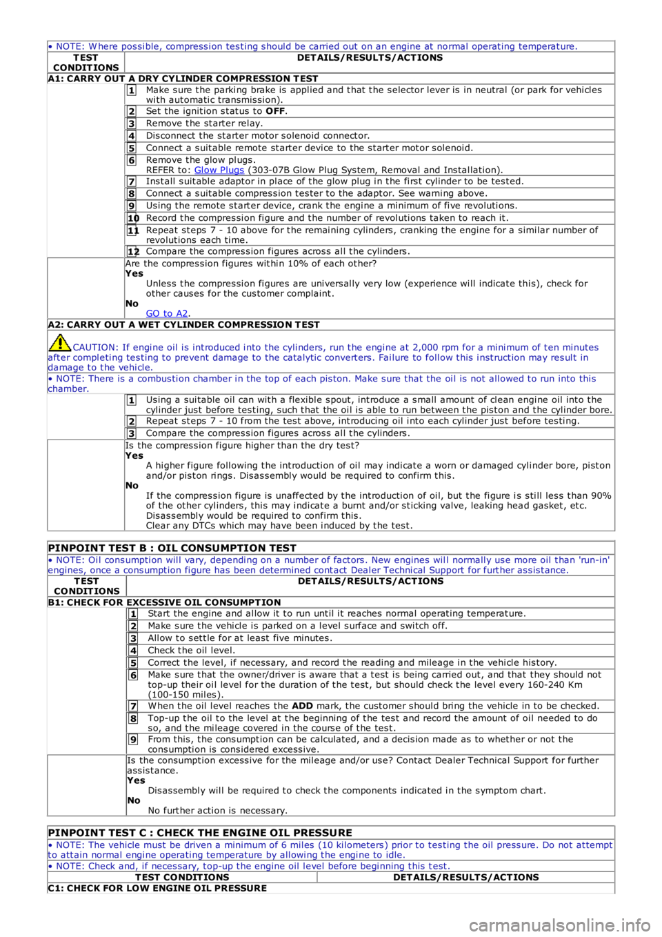
• NOTE: W here pos si ble, compress i on tes t ing s houl d be carried out on an engine at normal operat ing temperat ure.
T ESTCONDIT IONSDET AILS/RESULT S/ACT IONS
A1: CARRY OUT A DRY CYLINDER COMPRESSION T EST
Make s ure t he parki ng brake is appl ied and t hat t he s elector l ever is in neutral (or park for vehi cl eswi th aut omati c transmis si on).
Set the ignit ion s t at us t o OFF.
Remove t he st art er rel ay.
Dis connect t he st art er motor s olenoid connect or.
Connect a s uit able remote st art er devi ce to the s t art er mot or s ol enoi d.
Remove t he glow pl ugs .REFER to: Gl ow Plugs (303-07B Glow Plug Sys tem, Removal and Ins tal lati on).
Ins t all s uit abl e adapt or in pl ace of t he glow plug i n t he fi rs t cyl inder to be tes t ed.
Connect a s uit able compres s ion t es ter t o the adapt or. See warni ng above.
Us ing t he remote s t art er device, crank t he engi ne a mi nimum of fi ve revoluti ons.
Record t he compres si on fi gure and t he number of revol uti ons taken to reach it .
Repeat s t eps 7 - 10 above for t he remai ning cylinders , cranking t he engine for a s imi lar number ofrevolut ions each ti me.
Compare the compres s ion figures acros s al l t he cylinders .
Are the compres s ion figures wit hi n 10% of each ot her?YesUnles s t he compres si on fi gures are uni vers al ly very low (experience wi ll indicat e thi s), check forother caus es for the cus tomer complaint .NoGO to A2.
A2: CARRY OUT A WET CYLINDER COMPRESSIO N T EST
CAUTION: If engi ne oil i s int roduced i nto the cyli nders, run t he engi ne at 2,000 rpm for a mi ni mum of t en mi nutesaft er compl eti ng tes t ing t o prevent damage to the catal yt ic convert ers . Fai lure to foll ow t his i nst ruct ion may res ul t indamage t o t he vehi cl e.
• NOTE: There is a combus ti on chamber i n the top of each pis ton. Make s ure that the oi l is not all owed t o run into thi schamber.Us ing a sui table oil can wit h a flexibl e s pout , int roduce a s mall amount of cl ean engi ne oil int o t hecyl inder jus t before tes t ing, such t hat the oi l i s able to run between t he pis t on and t he cyl inder bore.Repeat s t eps 7 - 10 from the tes t above, int roduci ng oil i nt o each cyl inder jus t before tes ti ng.
Compare the compres s ion figures acros s al l t he cylinders .
Is the compres s ion figure higher than t he dry tes t?YesA hi gher figure foll owing t he int roducti on of oi l may indi cat e a worn or damaged cyli nder bore, pi st onand/or pis t on ri ngs . Dis as s embl y would be required to confirm t his .NoIf the compres s ion figure is unaffect ed by t he int roducti on of oi l, but t he fi gure is s ti ll les s t han 90%of the ot her cyl inders , thi s may i ndi cat e a burnt and/or s t icking valve, leaking head gasket , et c.Dis as s embl y would be required to confirm t his .Clear any DTCs which may have been i nduced by t he tes t .
PINPOINT TEST B : OIL CONSUMPTION TEST
• NOTE: Oi l cons umpti on wil l vary, dependi ng on a number of fact ors . New engines will normall y us e more oil t han 'run-in'engines, once a cons umpt ion fi gure has been det ermined cont act Deal er Techni cal Support for furt her as s is t ance.T ESTCO NDIT IONSDET AILS/RESULT S/ACT IONS
B1: CHECK FOR EXCESSIVE OIL CONSUMPT IONStart the engine and al low it t o run unt il i t reaches normal operat ing temperat ure.
Make s ure t he vehi cl e i s parked on a l evel s urface and swi tch off.
All ow t o s et t le for at least five minutes .
Check t he oil l evel.
Correct t he level, i f necess ary, and record t he reading and mileage i n t he vehi cl e his t ory.
Make s ure t hat the owner/dri ver i s aware that a t est i s being carried out , and that t hey should nottop-up their oi l level for the durat ion of t he t est , but should check t he level every 160-240 Km(100-150 mil es ).
W hen t he oil l evel reaches the ADD mark, t he cust omer s houl d bri ng the vehicle in to be checked.
Top-up t he oil t o the level at t he beginning of t he tes t and record the amount of oil needed to dos o, and t he mi leage covered in the cours e of t he tes t .
From this , t he cons umpt ion can be calculated, and a decis ion made as to whet her or not t hecons umpti on is cons idered excess ive.Is the consumpt ion excess ive for the mil eage and/or us e? Contact Dealer Technical Support for furtherass is t ance.YesDis as sembl y wil l be required t o check t he components indicated i n t he s ympt om chart .NoNo furt her acti on is necess ary.
PINPOINT TEST C : CHECK THE ENGINE OIL PRESSU RE
• NOTE: The vehicle must be driven a minimum of 6 mil es (10 ki lometers ) prior t o t est ing t he oil press ure. Do not at temptt o att ain normal engi ne operati ng temperature by all owi ng t he engi ne to idle.
• NOTE: Check and, i f neces sary, t op-up t he engine oil l evel before begi nning t his test .
T EST CO NDIT IONSDET AILS/RESULT S/ACT IONSC1: CHECK FOR LOW ENGINE OIL PRESSURE
Page 821 of 3229
18.
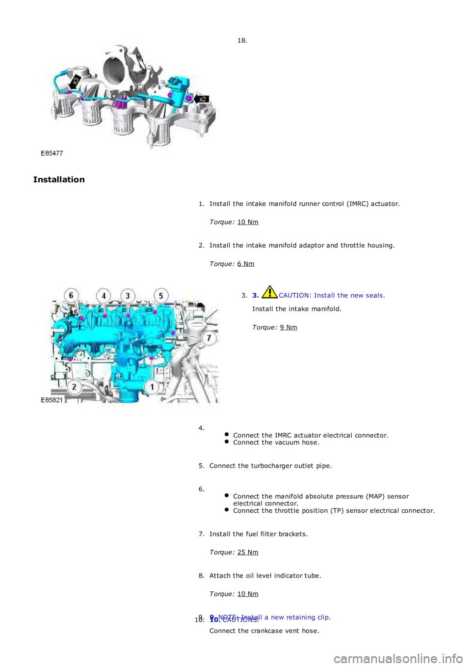
Installation Inst all t he int ake mani fol d runner cont rol (IMRC) actuator.
T orque: 10 Nm 1.
Inst all t he int ake mani fol d adapt or and throt t le hous ing.
T orque: 6 Nm 2.
3. CAUTION: Inst all t he new s eal s .
Inst all t he int ake mani fol d.
T orque: 9 Nm 3.
Connect t he IMRC act uator electrical connect or. Connect t he vacuum hos e.4.
Connect t he turbocharger outl et pi pe.
5.
Connect t he manifold abs olute pres sure (MAP) sens or
electrical connect or. Connect t he thrott le pos it ion (TP) s ens or electrical connect or.6.
Inst all t he fuel fi lt er bracket s.
T orque: 25 Nm 7.
At tach t he oil level indicator t ube.
T orque: 10 Nm 8.
9. NOTE: Ins t al l a new retaini ng clip.
Connect t he crankcas e vent hos e.
9.
10. CAUTIONS:
10.
Page 882 of 3229
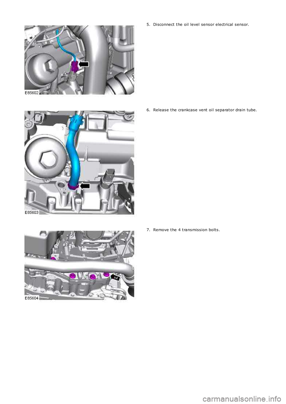
Di sconnect t he oil level sens or elect rical s ens or.5.
Releas e t he crankcas e vent oi l separat or drain tube.6.
Remove t he 4 t rans mis s ion bolt s .7.