2006 LAND ROVER FRELANDER 2 oil level
[x] Cancel search: oil levelPage 1277 of 3229
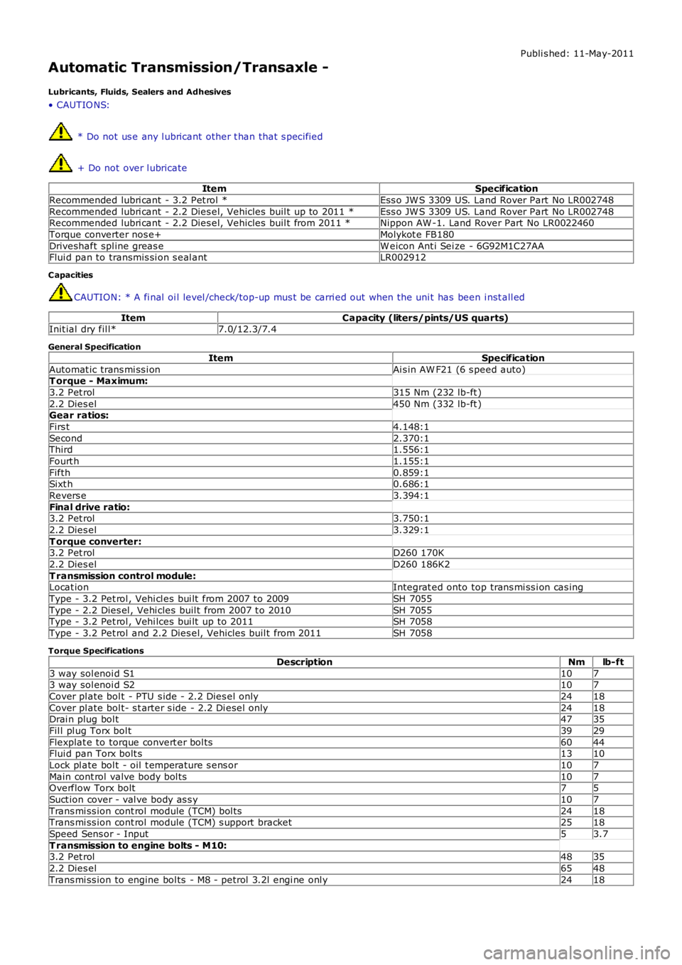
Publi s hed: 11-May-2011
Automatic Transmission/Transaxle -
Lubricants, Fluids, Sealers and Adhesives
• CAUTIO NS:
* Do not us e any l ubricant other t han that s pecified
+ Do not over l ubricate
ItemSpecification
Recommended lubri cant - 3.2 Pet rol *Ess o JW S 3309 US. Land Rover Part No LR002748
Recommended lubri cant - 2.2 Dies el, Vehicles buil t up to 2011 *Ess o JW S 3309 US. Land Rover Part No LR002748Recommended lubri cant - 2.2 Dies el, Vehicles buil t from 2011 *Nippon AW -1. Land Rover Part No LR0022460
Torque converter nos e+Molykot e FB180
Driveshaft spl ine greas eW eicon Ant i Sei ze - 6G92M1C27AAFlui d pan to transmis si on s eal antLR002912
C apacities
CAUTION: * A fi nal oi l level /check/top-up mus t be carri ed out when the uni t has been i nst all ed
ItemCapacity (liters/pints/US quarts)Init ial dry fil l*7.0/12.3/7.4
General Specification
ItemSpecification
Automat ic trans mi ss i onAi s in AW F21 (6 s peed auto)T orque - Maximum:
3.2 Pet rol315 Nm (232 lb-ft )
2.2 Dies el450 Nm (332 lb-ft )Gear ratios:
Firs t4.148:1
Second2.370:1Third1.556:1
Fourt h1.155:1
Fifth0.859:1Sixt h0.686:1
Revers e3.394:1
Final drive ratio:3.2 Pet rol3.750:1
2.2 Dies el3.329:1
T orque converter:3.2 Pet rolD260 170K
2.2 Dies elD260 186K2
T ransmission control module:Locat ionIntegrat ed onto top trans mi ss i on cas ing
Type - 3.2 Pet rol , Vehi cl es bui lt from 2007 to 2009SH 7055
Type - 2.2 Dies el , Vehi cles buil t from 2007 t o 2010SH 7055Type - 3.2 Pet rol , Vehi lces bui lt up to 2011SH 7058
Type - 3.2 Pet rol and 2.2 Dies el, Vehicles buil t from 2011SH 7058
Torque Specifications
DescriptionNmlb-ft
3 way sol enoi d S11073 way sol enoi d S2107
Cover pl ate bol t - PTU s ide - 2.2 Dies el onl y2418
Cover pl ate bol t- s t arter s ide - 2.2 Di esel only2418Drai n plug bol t4735
Fil l pl ug Torx bol t3929
Flexplat e to torque convert er bol ts6044Flui d pan Torx bolt s1310
Lock pl ate bol t - oil t emperature s ens or107
Main cont rol valve body bol ts107Overflow Torx bolt75
Suct ion cover - val ve body as s y107
Trans mi ss ion cont rol module (TCM) bol ts2418Trans mi ss ion cont rol module (TCM) s upport bracket2518
Speed Sens or - Input53.7
T ransmission to engine bolts - M10:3.2 Pet rol4835
2.2 Dies el6548
Trans mi ss ion to engine bol ts - M8 - petrol 3.2l engi ne onl y2418
Page 1280 of 3229
6-Clut ch - C3
7-Torque converter
8-Fluid pump9-Different ial as sembl y
10-Count er dri ven gear
11-Count er dri ve gearThe main cas ing ret ai ns the fl ui d at t he bot t om. A combined drai n/fill er plug i s located i n t he bot t om of t he cas ing. The oillevel is checked by removing t he inner fi ll plug when the t rans mis s ion flui d is at a t emperature of bet ween 50 t o 60°C (122t o 140°F). W hen the oi l fl ow becomes a dri p from the pl ug hol e, the l evel i s correct.
The t ransmis s ion has a flui d cool er whi ch is locat ed on t he Left Hand (LH) end of t he radi ator. The cooler is connect ed t ot he trans mi s si on convert er hous ing by 2 pipes . The fl ui d cooler is connect ed int o t he engi ne cool ing s yst em and cools thet ransmis s ion fluid by heat t rans fer t hrough t he cooler t o t he engi ne cool ant .For addit ional informat ion, refer t o: Trans mis s ion Cooli ng (307-02 Trans mis s ion/Trans axle Cooli ng, Des cri pti on andOperat ion).
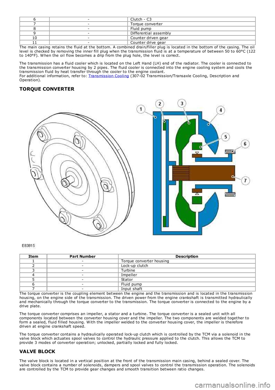
TORQUE CONVERTER
ItemPart NumberDescription1-Torque convert er hous ing
2-Lock-up clut ch
3-Turbine4-Impell er
5-St ator
6-Fl uid pump7-Input shaft
The t orque convert er is t he coupl ing el ement bet ween the engine and the t rans mis s ion and is l ocat ed in t he t rans mis s ionhous i ng, on t he engine s ide of t he t rans mis s ion. The dri ven power from the engine cranks haft i s transmit ted hydrauli cal lyand mechani cal ly t hrough t he torque convert er t o t he t rans mis s ion. The torque convert er is connect ed to the engine by adri ve plate.
The t orque convert er compris es an i mpeller, a s tat or and a t urbine. The torque convert er is a sealed uni t wit h allcomponents locat ed between the converter housi ng cover and t he impel ler. The t wo component s are welded t oget her t oform a s eal ed, flui d fi ll ed hous ing. W it h the impell er welded t o the convert er hous ing cover, the impell er is t hereforedri ven at engine cranks haft s peed.
The t orque convert er cont ai ns a hydrauli cal ly operat ed lock-up clut ch which i s cont roll ed by t he TCM via a s olenoid i n t hevalve block which actuat es s pool valves to cont rol the hydraul ic pres s ure appli ed t o t he cl utch. Thi s all ows the TCM t oprovide 3 modes of convert er operat ion; unlocked, part iall y l ocked and ful ly l ocked.
VALVE BLOCK
The valve block is locat ed i n a vert ical pos i ti on at the front of t he transmis si on mai n cas i ng, behind a sealed cover. Thevalve block cont ains a number of s olenoids , dampers and s pool valves to cont rol t he trans mi s si on operati on. The s olenoidsare cont roll ed by t he TCM t o provide gear changes and s mooth trans i ti on bet ween rat io changes.
Page 1556 of 3229
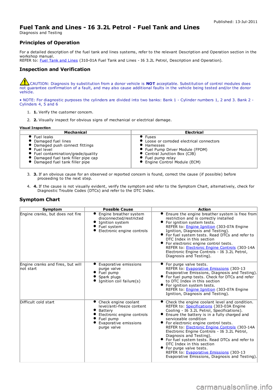
Publi shed: 13-Jul-2011
Fuel Tank and Lines - I6 3.2L Petrol - Fuel Tank and Lines
Diagnosi s and Tes ti ng
Principles of Operation
For a detail ed descripti on of the fuel tank and l ines s ys t ems , refer t o t he rel evant Des cript ion and Operat ion s ecti on in theworks hop manual .REFER to: Fuel Tank and Lines (310-01A Fuel Tank and Lines - I6 3.2L Pet rol , Descri pti on and Operat ion).
Inspection and Verification
CAUTION: Di agnos is by s ubs ti tut ion from a donor vehicle is NO T acceptabl e. Subs ti tut ion of cont rol modules doesnot guarant ee confirmat ion of a faul t, and may als o caus e addit ional fault s i n t he vehi cl e being t est ed and/or t he donorvehi cl e.
• NOTE: For di agnos t ic purpos es the cyli nders are divided i nt o t wo banks: Bank 1 - Cyl inder numbers 1, 2 and 3. Bank 2 -Cylinders 4, 5 and 6
1. Verify t he cus t omer concern.1.
2. Vis ually ins pect for obvious s igns of mechani cal or electrical damage.2.
Visual Inspection
MechanicalElectricalFuel l eaksDamaged fuel l inesDamaged push connect fit t ingsFuel l evelFuel contami nati on/grade/quali tyDamaged fuel t ank fi ller pipe capDamaged fuel t ank fi ller pipe
FusesLoos e or corroded elect rical connect orsHarnes s esFuel Pump Dri ver Module (FPDM)Central Junct ion Box (CJB)Fuel pump relayEngine Control Modul e (ECM)
3. If an obvious cause for an obs erved or report ed concern is found, correct t he caus e (if pos s ible) beforeproceeding t o t he next s t ep.3.
4. If t he caus e is not vis ually evi dent , verify t he sympt om and refer t o t he Sympt om Chart, al ternat ively, check forDi agnos ti c Trouble Codes (DTCs) and refer t o t he DTC Index.4.
Symptom Chart
SymptomPossible CauseAction
Engine cranks , but does not fi reEngine breat her sys temdi sconnect ed/res trict edIgnit ion s yst emFuel sys temEl ect ronic engine controls
Ens ure t he engi ne breat her s ys tem is free fromres t ri ct ion and is correct ly i nst all edFor ignit ion s ys tem tes t s.REFER to: Engine Ignit ion (303-07A EngineIgni ti on, Di agnos is and Tes t ing).For fuel s ys t em t est s . Read DTCs and refer t oDTC Index in t his secti onFor elect roni c engi ne cont rol t es t s .REFER to: El ect ronic Engine Cont rols (303-14AElectronic Engine Controls - I6 3.2L Petrol ,Di agnos is and Tes ti ng).
Engine cranks and fires , but wil lnot s tartEvaporati ve emis s ionspurge val veFuel pumpSpark pl ugsIgnit ion coil fai lure(s )
For purge valve t est s .REFER to: Evaporati ve Emis s ions (303-13Evaporati ve Emis s ions, Di agnos is and Tes t ing).For fuel pump t es t s . Check for DTCs and refert o DTC Index in t his s ecti onFor ignit ion s ys tem tes t s.REFER to: Engine Ignit ion (303-07A EngineIgni ti on, Di agnos is and Tes t ing).
Di fficul t col d s t artCheck engi ne cool antl evel /anti -freeze cont entBat teryEl ect ronic engine controlsFuel pumpEvaporati ve emis s ionspurge val ve
Check the engine coolant level and condit ion.REFER to: Specifi cat ions (303-03A EngineCooli ng - I6 3.2L Petrol, Speci fi cat ions ).Ens ure t he batt ery i s in a ful ly charged ands erviceable condi ti onFor elect roni c engi ne cont rol t es t s .REFER to: El ect ronic Engine Cont rols (303-14AElectronic Engine Controls - I6 3.2L Petrol ,Di agnos is and Tes ti ng).For fuel s ys t em t est s . Read DTCs and refer t oDTC Index in t his secti onFor purge valve t est s .REFER to: Evaporati ve Emis s ions (303-13Evaporati ve Emis s ions, Di agnos is and Tes t ing).
Page 1655 of 3229
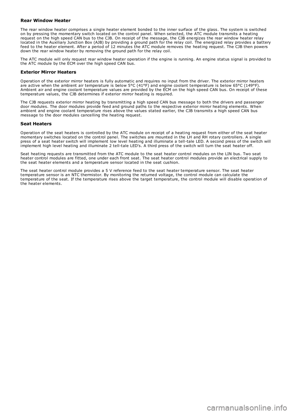
Rear Window Heater
The rear window hea ter comprise s a single heat er e leme nt bonded to the inner surf ace of t he glass . The syste m is swi tche don by pre ssing the mome nta ry s witch locate d on the control panel. W he n se lected, the ATC module tra nsmits a he atingreque st on the high spee d CAN bus to the CJB. On recei pt of the me ssa ge, the CJB energiz es t he rear window hea ter relayl ocat ed i n the Auxilia ry Junct ion Box (AJB) by providing a ground pa th for the re lay coil. The energiz ed relay provide s a bat teryf eed to t he heat er e leme nt. Afte r a period of 12 minute s the ATC module re moves the heat ing request . The CJB then powe rsdown the rea r wi ndow he ate r by removing the ground pa th f or t he relay coil .
The ATC module will only reques t re ar window heate r opera tion if the e ngine is running. An engine stat us s ignal is provide d tot he ATC module by t he ECM over the high speed CAN bus.
Exterior Mirror Heaters
O peration of the ext erior mirror heat ers is fully a utomat ic a nd re qui res no input from the driver. The exterior mirror hea tersa re a ctive when the ambient air tempera ture is below 5°C (41°F) and e ngine coolant te mpe rature i s be low 65° C (149° F).Ambi ent air a nd engine coola nt t empera ture val ues are provided by the ECM on the high speed CAN bus. O n re ceipt of the set emperat ure values, the CJB det ermines if e xterior mirror he ating is require d.
The CJB requests exterior mirror hea ting by transmit ting a high spe ed CAN bus mes sage to bot h the drivers and pa sse ngerdoor module s. The door modules provide fee d and ground paths to the respecti ve e xterior mirror he ating el eme nts . W hena mbi ent and engine cool ant tempera ture ris es a bove the va lues sta ted earl ier, the CJB transmi ts a high speed CAN busmess age to the door module s ca nce lling the hea ting reques t.
Seat Heaters
O peration of the sea t he aters is controll ed by the ATC module on re ceipt of a heati ng reque st f rom either of the se at heat ermomenta ry s witches loca ted on the cont rol pane l. The s witches are mounte d in the LH and RH rota ry controllers. A singlepress of a se at heat er switch wi ll implement low level heati ng a nd illumina te a tell-tale LED. A second pre ss of the switch willi mple me nt high l eve l hea ting and ill uminate 2 te ll-t ale LED's. A third press of t he s witch will turn t he s eat hea ter off.
Seat hea ting request s are transmitte d from the ATC module to the seat hea ter control modules on the LIN bus . Two se atheat er control modul es a re f itted, one under each front seat . The se at heat er control modules provide an e lect rical supply tot he s eat hea ter e lement s and a tempera ture sensor loca ted in t he s eat cus hion.
The s eat hea ter cont rol module provides a 5 V reference fee d to the sea t he ate r te mpe rature s ensor. The s eat hea tert emperat ure sensor is an NTC thermistor. By monitoring the ret urne d voltage, t he control module can calculate thet emperat ure of t he s eat. If t he t empera ture rise s above the target tempera ture , the control module wi ll dis abl e operat ion oft he heat er e leme nts .
Page 1853 of 3229
1. CAUTION: Make s ure that the mati ng faces are cl ean and
free of foreign mat eri al.
Inst all t he generat or.
1.
Inst all t he 2 generator bolt s .
T orque: 48 Nm 2.
Inst all t he acces sory dri ve bel t idl er pull ey.
T orque: 48 Nm 3.
Inst all t he acces sory dri ve bel t idl er pull ey dust cap.
4.
Connect t he generator electrical connect or.
5.
Connect t he batt ery cable t o t he generator.
T orque: 24 Nm 6.
At tach t he power s t eering flui d res ervoir.
7.
8. CAUTION: Make s ure that the mati ng faces are cl ean and
free of foreign mat eri al.
Inst all t he power s t eering pump.
T orque: 24 Nm 8.
Inst all t he fuel fi lt er support bracket.
T orque: 20 Nm 9.
At tach t he oil level indicator t ube to the fuel fil ter s upport bracket .
T orque: 10 Nm 10.
Inst all t he inner fuel fi lt er shi el d.
11.
Secure t he cool ant t op hos e.
12.
Inst all t he acces sory dri ve bel t.
Refer t o: Acces sory Dri ve Belt (303-05B Acces sory Drive - TD4 2.2L
Di es el, Removal and Ins tal lat ion).
13.
Inst all t he engi ne undershi eld.
Refer t o: Engi ne Unders hi eld (501-02 Front End Body Panel s ,
Removal and Ins tall ati on).
14.
Inst all t he fuel fi lt er.
Refer t o: Fuel Fil ter (310-01B Fuel Tank and Lines - TD4 2.2L Dies el ,
Removal and Ins tall ati on).
15.
Page 2030 of 3229
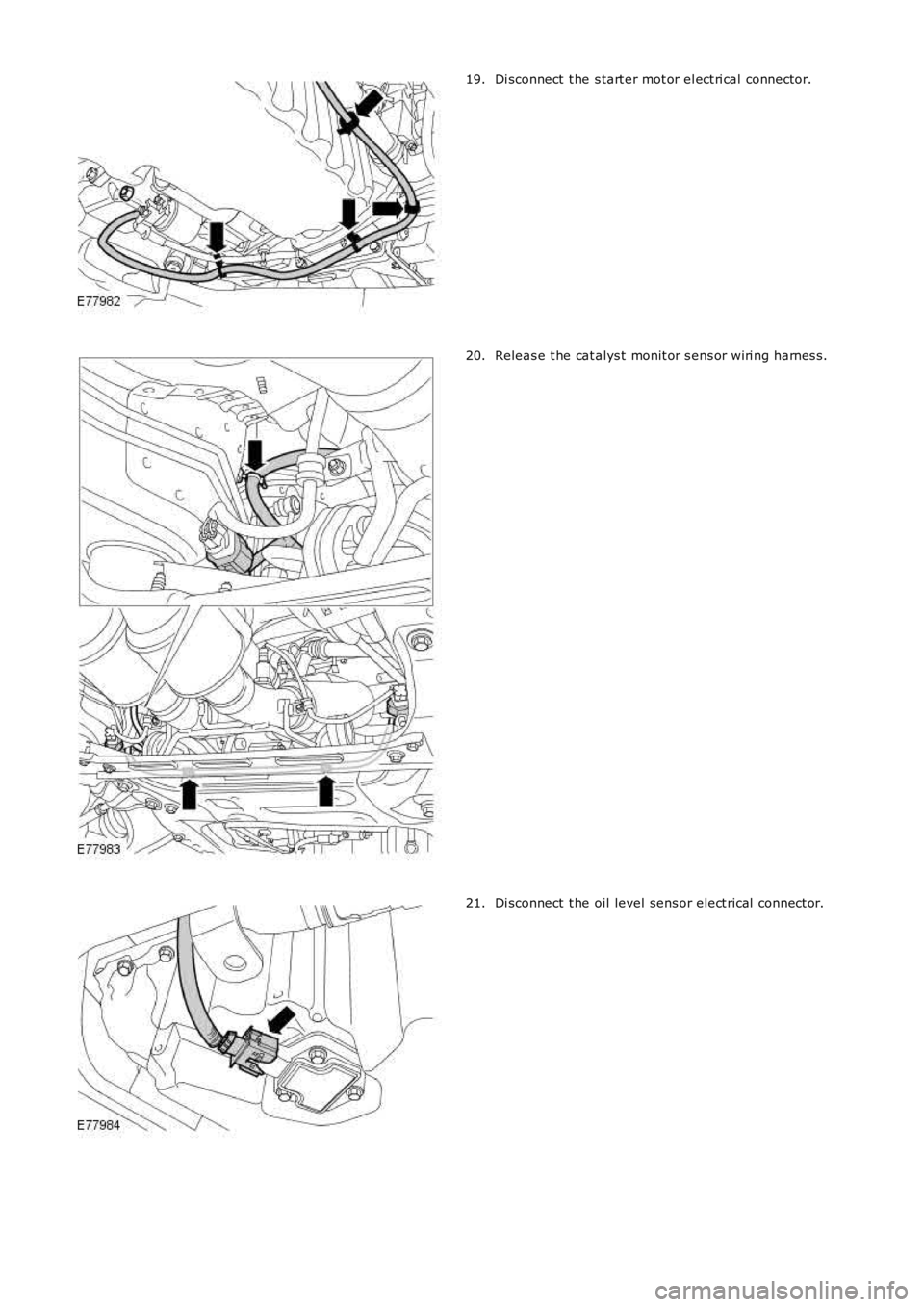
Di sconnect t he s tart er mot or el ect ri cal connector.19.
Releas e t he cat alys t monit or s ens or wiri ng harnes s.20.
Di sconnect t he oil level sens or elect rical connect or.21.
Page 2033 of 3229
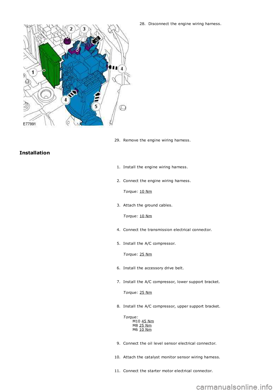
Di sconnect t he engi ne wiring harnes s .
28.
Remove t he engi ne wiring harnes s .
29.
Installation
Inst all t he engi ne wiring harnes s .
1.
Connect t he engi ne wiring harnes s .
T orque: 10 Nm 2.
At tach t he ground cabl es.
T orque: 10 Nm 3.
Connect t he transmis s ion electrical connect or.
4.
Inst all t he A/C compress or.
T orque: 25 Nm 5.
Inst all t he acces sory dri ve bel t.
6.
Inst all t he A/C compress or, l ower support bracket.
T orque: 25 Nm 7.
Inst all t he A/C compress or, upper s upport bracket.
T orque: M10 45 Nm M8
25 Nm M6
10 Nm 8.
Connect t he oil level s ens or electrical connect or.
9.
At tach t he cat alys t monit or s ens or wiri ng harnes s.
10.
Connect t he s tarter mot or el ect ri cal connector.
11.
Page 2724 of 3229

Contents
4
L
Climate control
AIR VENTS ................................................... 101
MANUAL CLIMATE CONTROL ...................... 102
AUTOMATIC CLIMATE CONTROL ................. 103
HEATED WINDOWS AND MIRRORS ............ 104
AUXILIARY HEATER ..................................... 104
ELECTRIC SUNROOF .................................... 105
Convenience features
SUN VISORS ................................................ 107
CLOCK .......................................................... 107
CIGAR LIGHTER ........................................... 109
ASHTRAY ..................................................... 109
AUXILIARY POWER SOCKETS ..................... 110
CUP HOLDERS ............................................. 111
STORAGE COMPARTMENTS ........................ 112
Starting the engine
GENERAL INFORMATION ............................. 113
STARTING A PETROL ENGINE ..................... 114
STARTING A DIESEL ENGINE ....................... 115
DIESEL PARTICULATE FILTER (DPF) ........... 116
Transmission
MANUAL TRANSMISSION ............................ 118
AUTOMATIC TRANSMISSION ...................... 118
TECHNICAL SPECIFICATIONS ...................... 122
Brakes
PRINCIPLE OF OPERATION .......................... 123
HINTS ON DRIVING WITH ABS .................... 123
PARKING BRAKE .......................................... 124
Parking aid
PRINCIPLE OF OPERATION .......................... 126
USING THE PARKING AID ............................ 127
Driving hints
GENERAL DRIVING POINTS ......................... 128
REDUCED ENGINE PERFORMANCE ............. 128
RUNNING-IN ................................................ 128
ECONOMICAL DRIVING ................................ 129
Cruise control
PRINCIPLE OF OPERATION .......................... 130
USING CRUISE CONTROL ............................ 130
Terrain response
PRINCIPLE OF OPERATION .......................... 132
USING TERRAIN RESPONSE ........................ 132
Hill descent control (HDC)
PRINCIPLE OF OPERATION .......................... 136
USING HDC ................................................... 137
Traction control
USING TRACTION CONTROL ........................ 139
Stability control
PRINCIPLE OF OPERATION .......................... 140
USING STABILITY CONTROL ........................ 141
Fuel and refuelling
SAFETY PRECAUTIONS................................. 142
FUEL QUALITY .............................................. 142
RUNNING OUT OF FUEL................................ 144
FUEL CUT-OFF............................................... 144
FUEL FILLER FLAP ........................................ 144
REFUELLING ................................................. 145
TECHNICAL SPECIFICATIONS ....................... 146
Load carrying
GENERAL INFORMATION.............................. 147
LUGGAGE ANCHOR POINTS ......................... 148
LUGGAGE COVERS ....................................... 149
Towing
TOWING A TRAILER...................................... 150
LEVELLING.................................................... 151
ESSENTIAL TOWING CHECKS ...................... 151
RECOMMENDED TOWING WEIGHTS ............ 152
TOW BAR ...................................................... 153
Vehicle care
CLEANING THE ALLOY WHEELS................... 154
CLEANING THE EXTERIOR ............................ 154
CLEANING THE INTERIOR ............................ 155
REPAIRING MINOR PAINT DAMAGE ............ 156
Maintenance
GENERAL INFORMATION.............................. 157
OPENING AND CLOSING THE BONNET......... 160
ENGINE COMPARTMENT OVERVIEW ........... 161
ENGINE OIL CHECK....................................... 162