2006 LAND ROVER FRELANDER 2 oil level
[x] Cancel search: oil levelPage 883 of 3229
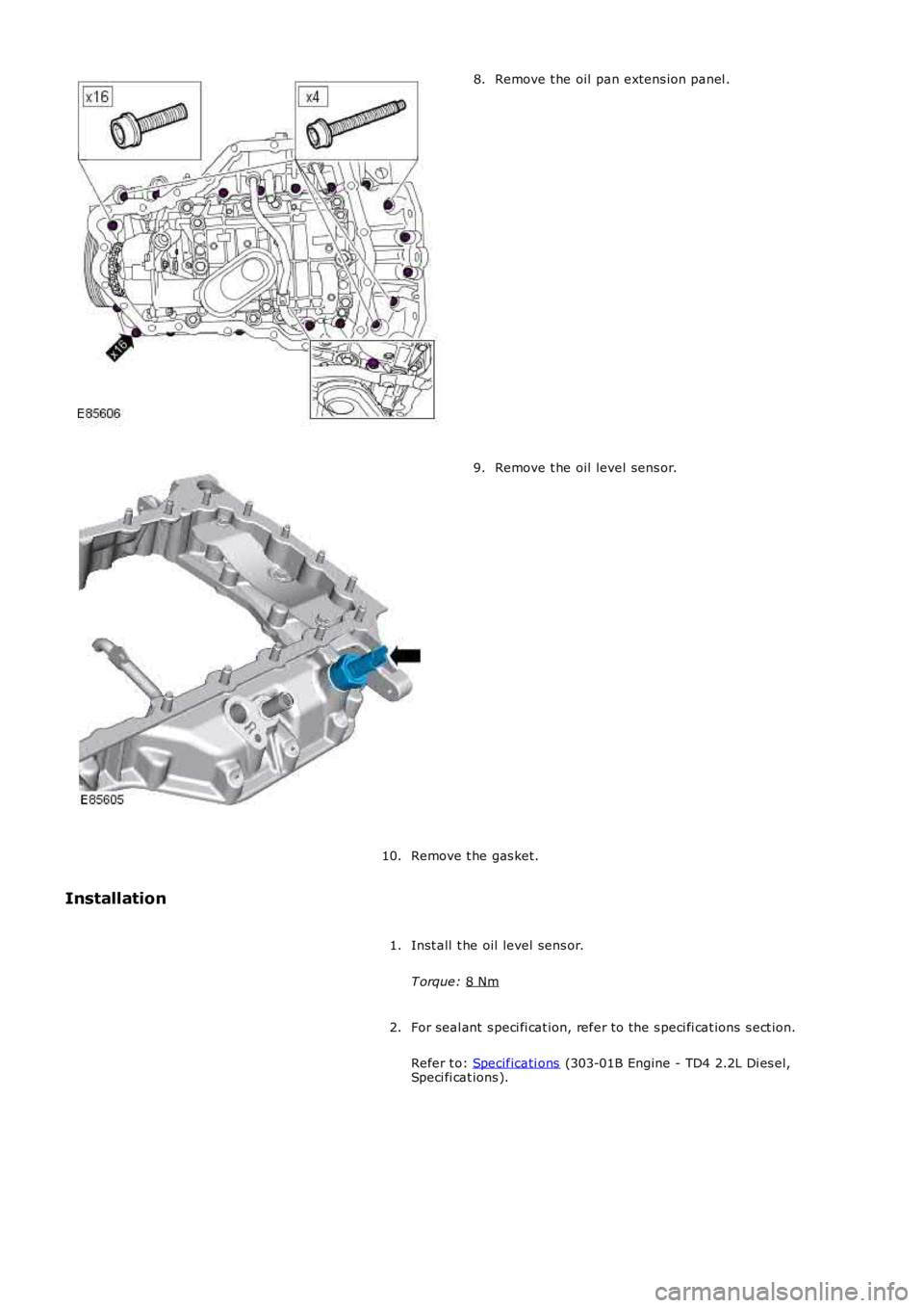
Remove t he oil pan extens ion panel .
8. Remove t he oil level sens or.
9.
Remove t he gas ket.
10.
Installation
Inst all t he oil level sens or.
T orque: 8 Nm 1.
For seal ant s peci fi cat ion, refer to t he s peci fi cat ions s ect ion.
Refer t o: Specificati ons (303-01B Engine - TD4 2.2L Di es el,
Speci fi cat ions ).
2.
Page 884 of 3229
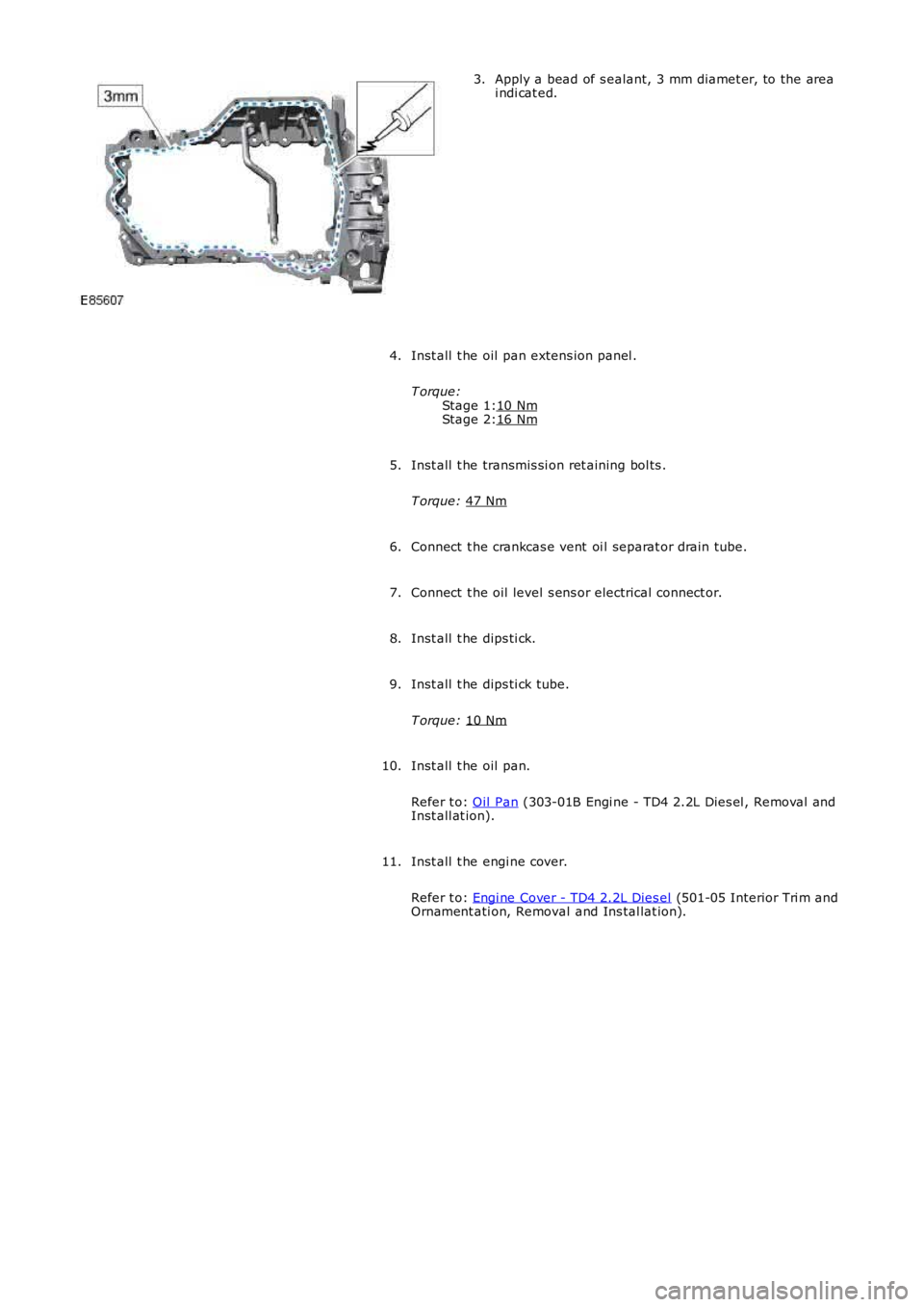
Stage 1:
Stage 2: Apply a bead of s ealant, 3 mm diamet er, to the area
i ndi cat ed.
3.
Inst all t he oil pan extens ion panel .
T orque: 10 Nm 16 Nm4.
Inst all t he transmis si on ret aining bol ts .
T orque: 47 Nm 5.
Connect t he crankcas e vent oi l separat or drain tube.
6.
Connect t he oil level s ens or electrical connect or.
7.
Inst all t he dips ti ck.
8.
Inst all t he dips ti ck tube.
T orque: 10 Nm 9.
Inst all t he oil pan.
Refer t o: Oil Pan (303-01B Engi ne - TD4 2.2L Dies el , Removal and
Inst all at ion).
10.
Inst all t he engi ne cover.
Refer t o: Engi ne Cover - TD4 2.2L Dies el (501-05 Interior Tri m and
Ornament ati on, Removal and Ins tal lat ion).
11.
Page 943 of 3229
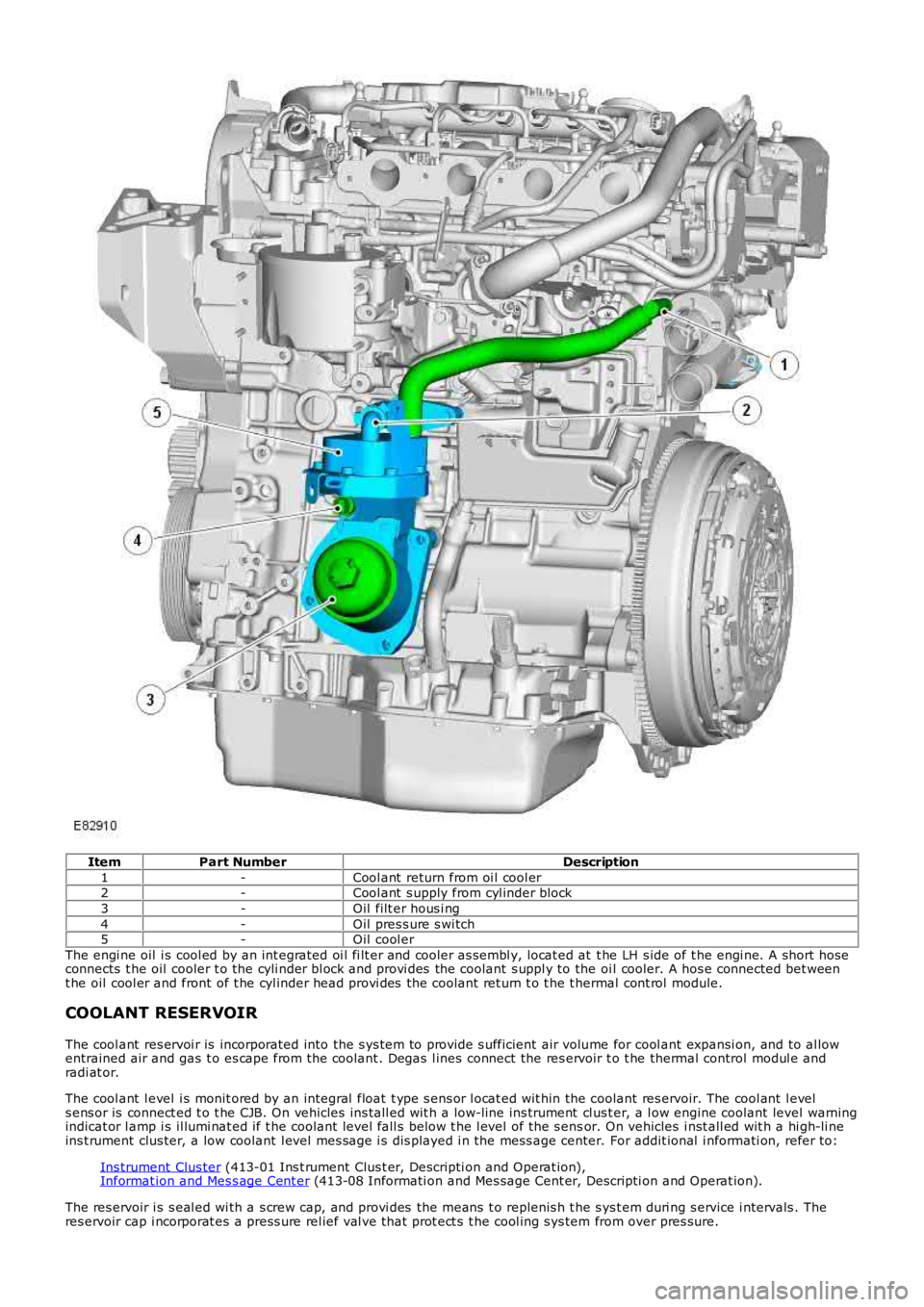
ItemPart NumberDescription
1-Cool ant return from oi l cool er2-Cool ant s upply from cyl inder block
3-Oil filt er hous i ng
4-Oil pres s ure s wi tch5-Oil cool er
The engi ne oil i s cool ed by an int egrated oi l fi lt er and cooler as sembl y, locat ed at t he LH s ide of t he engi ne. A s hort hoseconnects t he oil cooler t o the cyli nder bl ock and provi des the coolant s uppl y to the oi l cooler. A hos e connected bet weent he oil cool er and front of t he cyl inder head provi des the coolant ret urn t o t he t hermal cont rol module.
COOLANT RESERVOIR
The cool ant res ervoi r is incorporated into the s ys tem to provide s ufficient air volume for cool ant expansi on, and to al lowentrained air and gas t o es cape from the coolant . Degas l ines connect the res ervoir t o t he thermal control modul e andradi at or.
The cool ant l evel i s monit ored by an integral float t ype s ens or l ocat ed wit hin the coolant res ervoir. The cool ant l evels ens or is connect ed t o t he CJB. On vehicles ins tall ed wit h a low-line ins trument cl us t er, a l ow engine coolant level warningindicat or l amp i s il lumi nat ed if t he coolant level fall s below t he l evel of the s ensor. On vehicles i nst all ed wit h a hi gh-li neins t rument clus ter, a low coolant l evel mes sage i s dis played i n the mess age center. For addit ional i nformati on, refer to:
Ins trument Clus ter (413-01 Ins t rument Clus t er, Descripti on and Operat ion),Informat ion and Mes s age Cent er (413-08 Informati on and Mes sage Cent er, Descripti on and Operat ion).
The res ervoir i s s eal ed wi th a s crew cap, and provi des the means t o replenis h t he s ys t em duri ng s ervice i ntervals . Theres ervoir cap i ncorporat es a press ure rel ief val ve that prot ect s t he cool ing s ys tem from over pres sure.
Page 946 of 3229
Entrained gases i n t he cool ing s ys tem escape t hrough the t hermal control modul e degas l ine t o t he cool ant res ervoir.
The increas ing coolant temperature is felt at t he t hermos tat , and is regi s tered on the ins trument cl us t er coolantt emperature gage vi a t he ECM and ECT s ens or s i gnal.For addit ional informat ion, refer t o: Ins t rument Clus ter (413-01 Inst rument Cl us t er, Des cript ion and Operat ion).
Engine Normal Operating Temperature
W i th the coolant t emperature increas ing, at 83°C (181°F) t he t hermos tat reacts and commences openi ng. The by-pas svalve is progres s ively clos ed. Hot coolant ret urning from t he engi ne t o t he thermal control modul e i s now all owed to pas st hrough the t op hos e connecti on to the radiator. The fl ow of hot coolant t o t he radiat or now forces cold cool ant wi thi n t heradi at or and bot t om hos e t o fl ow t o t he thermal cont rol module.
Duri ng the thermos t at opening period t here i s an i nit ial temperat ure di fferenti al of t he coolant at bot h s ides of t het hermos tat . The thermos t at react s t o t he t emperature different ial and part iall y closes , whi le t he by-pas s val ve opensfurther. The thermos t at and by-pas s valve conti nue to oscil lat e whil e t he cool ant t emperat ure i ncreas es .
At a coolant temperat ure of 91°C (196°F) t he thermost at is full y opened and t he by-pas s valve i s ful ly clos ed. The returncool ant from t he engi ne is now ful ly circul ated t hrough t he radiat or and bot tom hose. Coolant flows t hrough the radiat orfrom the RH tank t o t he LH t ank, and i s cool ed by air pass i ng through the mat ri x. Ent rai ned gas es i n the radiat or es capet hrough the connect ed degas l ine t o t he cool ant res ervoir.
The increas ed cool ant volume created by heat expans ion caus es the coolant level to ri se through t he connecti ng res ervoirhose, and i nt o t he res ervoi r.
The t emperature of the cooli ng s ys t em i s cons t ant ly moni tored by t he ECM via the ECT s ens or s i gnal. The ECM uses t heECT s ignal to control operati on of the cooling fans , and to adjus t engine fueling. The ECM al so operates t he fans i nres ponse to input s from the aut omati c t ransmis s ion oil t emperat ure s ensor, Air Condit ioning (A/C) s ys tem cont rol s wit ch,and t he A/C pres sure s ens or. For addit ional i nformati on, refer to: El ect ronic Engine Cont rols - 2.2L Di es el (303-14Electroni c Engine Controls - 2.2L Dies el, Des cript ion and Operat ion).For addit ional informat ion, refer t o: Air Condit ioning (412-01 Cli mat e Cont rol , Descripti on and Operat ion).
The cool ing fan s peed is als o infl uenced by vehicle road s peed. The ECM adjus t s the speed of t he cool ing fans tocompens ate for t he ram air effect , us ing t he CAN bus road speed s ignal received from the Ant i-Lock Brake Sys tem (ABS)module.
W hen t he engine i s s hut down, t he coolant t emperature and volume decreas e. The thermos t at st art s t o clos e as t hecool ant t emperat ure decreas es to 89°C (192°F), and is fully cl osed at 81°C (178°F). The coolant level wit hin t he res ervoi rdecreas es as coolant is drawn from the res ervoi r to replenis h the s ys tem.
Followi ng engi ne s hut down when the coolant pump i s s tat ionary, the ECM may cont inue t o operat e t he cool ing fans for apre-det ermined peri od to maint ai n engine cooling.
Page 1112 of 3229
Publi s hed: 11-May-2011
Engine Ignition - Engine Ignition
Des cript ion and Operat ion
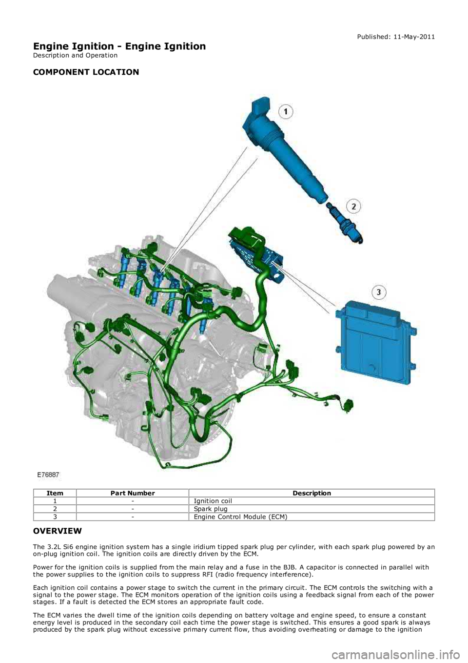
COMPONENT LOCATION
ItemPart NumberDescription1-Ignit ion coil
2-Spark plug
3-Engine Cont rol Module (ECM)
OVERVIEW
The 3.2L Si 6 engi ne igni ti on sys t em has a s i ngl e iridi um t ipped s park plug per cylinder, wit h each spark plug powered by anon-plug ignit ion coil . The ignit ion coil s are di rectl y dri ven by the ECM.
Power for the ignit ion coil s is suppli ed from t he mai n rel ay and a fus e in t he BJB. A capacit or is connected in paral lel wit ht he power s upplies t o t he i gni ti on coi ls t o s uppres s RFI (radi o frequency i nt erference).
Each ignit ion coil cont ains a power s t age to swi tch t he current i n t he pri mary ci rcuit . The ECM cont rol s the swi tching wit h as ignal to t he power s tage. The ECM monit ors operat ion of t he igni ti on coi ls us ing a feedback s i gnal from each of t he powers tages . If a fault i s det ected t he ECM s t ores an appropri ate fault code.
The ECM vari es the dwel l ti me of t he ignit ion coil s dependi ng on batt ery volt age and engi ne s peed, t o ensure a const antenergy level is produced i n the secondary coi l each t ime t he power s t age is s wi tched. This ens ures a good spark is al waysproduced by the s park pl ug wi thout exces si ve pri mary current fl ow, t hus avoi ding overheati ng or damage to t he i gni ti on
Page 1115 of 3229
Publi s hed: 11-May-2011
Engine Ignition - Engine Ignition
Diagnosi s and Tes ti ng
Principles of Operation
For a detail ed descripti on of the ignit ion s yst em, refer to the relevant Des cri pti on and Operati on s ect ion i n t he works hopmanual.REFER to: Engine Ignit ion (303-07A Engi ne Igni ti on, Des cript ion and O perati on).
Inspection and Verification
CAUTION: Di agnos is by s ubs ti tut ion from a donor vehicle is NO T acceptabl e. Subs ti tut ion of cont rol modules doesnot guarant ee confirmat ion of a faul t, and may als o caus e addit ional fault s i n t he vehi cl e being t est ed and/or t he donorvehi cl e.
1. Verify t he cus t omer concern.1.
2. Vis ually ins pect for obvious s igns of mechani cal or electrical damage.2.
Visual InspectionMechanicalElectrical
Engine oil l evelCooli ng sys t em cool ant levelFuel l evelFuel contami nati on/grade/quali ty
Fus esW iring harnes sLoos e or corroded electrical connect orsIgnit ion coil sSens or(s)Engine Cont rol Modul e (ECM)
3. If an obvious cause for an obs erved or report ed concern is found, correct t he caus e (if pos s ible) beforeproceeding t o t he next s t ep3.
4. If t he caus e is not vis ually evi dent , verify t he sympt om and refer t o t he Sympt om Chart, al ternat ively, check forDi agnos ti c Trouble Codes (DTCs) and refer t o t he DTC Index.4.
Symptom Chart
SymptomPossible CauseActionEngine cranks , but doesnot fi reEngine breat her sys temdis connected/res trict edEngine i gni ti on s ys t emFuel sys temElect ronic engine controls
Ens ure the engine breat her sys t em i s free fromres tricti on and is correctl y ins tal ledRead DTCs and refer t o DTC Index in t his s ecti on forengine ignit ion s ys tem tes tsFor fuel s yst em tes ts .REFER t o: Fuel Tank and Lines (310-01A Fuel Tank andLi nes - I6 3.2L Petrol, Diagnos is and Tes ti ng).Read DTCs and refer t o t he DTC Index for elect roni cengine cont rols .REFER t o: Electroni c Engi ne Control s (303-14AEl ect ronic Engi ne Cont rol s - I6 3.2L Pet rol, Di agnos isand Tes t ing).
Engine cranks and fires ,but wil l not s t artEvaporati ve emis s ionspurge val veFuel pumpSpark pl ugsHT short to ground(tracki ng) check rubberboots for cracks /damageIgni ti on coil fai lure(s )
For purge valve tes ts .REFER t o: Evaporat ive Emi s si ons (303-13 Evaporati veEmis s ions, Di agnos is and Tes t ing).For fuel s yst em tes ts .REFER t o: Fuel Tank and Lines (310-01A Fuel Tank andLi nes - I6 3.2L Petrol, Diagnos is and Tes ti ng).For s park pl ug tes ts , Vi suall y ins pect t he s park pl ug forcracks , damage, carbon buil dup or wet fouling, checkthe condi ti on of the ground electrode, t he cent erel ect rode t ip and the s park pl ug HT contact andconfi rm t hat t he s park pl ug gap is correct ly set us ing awire gauge taking care not t o cause damage to thecenter or ground el ect rode t ips . Ins tal l new s parkpl ug(s ) as required.For engine i gni ti on coi l ci rcuit t est s , check for DTCsand refer t o t he DTC Index
Di fficul t col d s t artEngine coolant level-anti -freeze contentBat teryElect ronic engine controlsFuel pumpPurge val ve
Check t he engi ne cool ant l evel and anti -freeze cont ent.REFER t o: Specificati ons (303-03A Engine Cool ing - I63.2L Petrol, Speci ficat ions).Ens ure the bat tery is i n a full y charged and s erviceabl econdit ionRead DTCs and refer t o DTC Index for electroni c enginecontrols .REFER t o: Electroni c Engi ne Control s (303-14AEl ect ronic Engi ne Cont rol s - I6 3.2L Pet rol, Di agnos isand Tes t ing).For fuel s yst em tes ts .REFER t o: Fuel Tank and Lines (310-01A Fuel Tank and
Page 1148 of 3229
18.
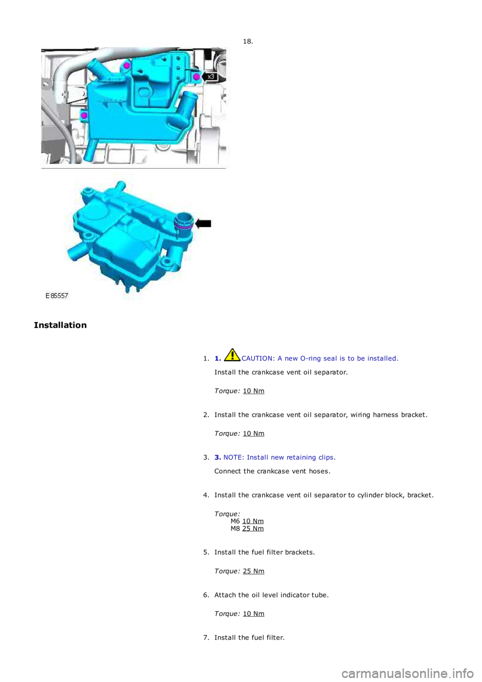
Installation 1. CAUTION: A new O-ring seal is to be ins tall ed.
Inst all t he crankcas e vent oi l separat or.
T orque: 10 Nm 1.
Inst all t he crankcas e vent oi l separat or, wi ri ng harness bracket .
T orque: 10 Nm 2.
3. NOTE: Ins t al l new ret aining cl ips .
Connect t he crankcas e vent hos es .
3.
Inst all t he crankcas e vent oi l separat or to cyli nder bl ock, bracket .
T orque: M6 10 Nm M8
25 Nm 4.
Inst all t he fuel fi lt er bracket s.
T orque: 25 Nm 5.
At tach t he oil level indicator t ube.
T orque: 10 Nm 6.
Inst all t he fuel fi lt er.
7.
Page 1169 of 3229
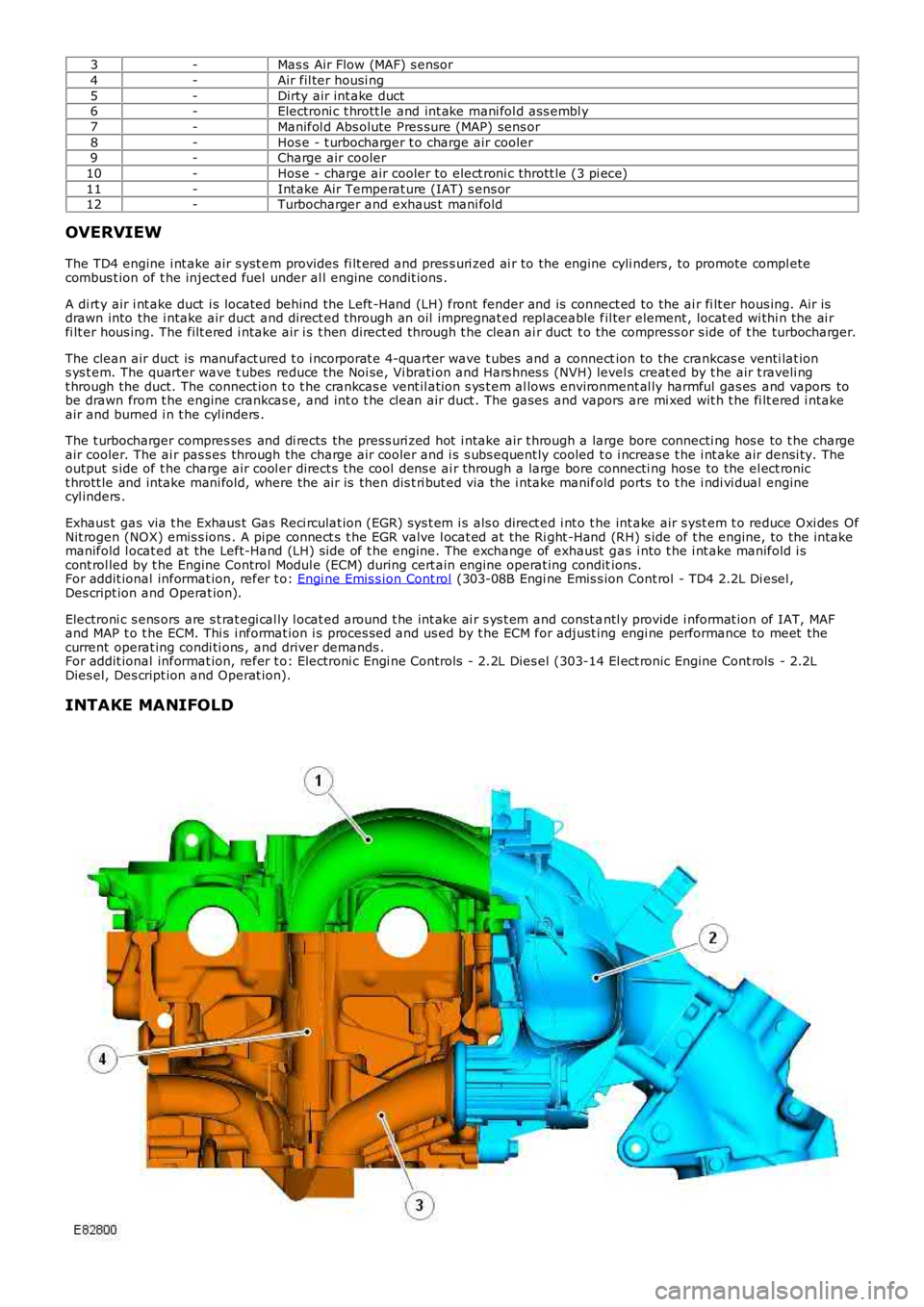
3-Mas s Air Flow (MAF) s ensor
4-Air fil ter housi ng
5-Dirty air int ake duct6-Electroni c t hrott le and int ake mani fol d ass embl y
7-Manifol d Abs olute Pres sure (MAP) sens or
8-Hos e - t urbocharger t o charge air cooler9-Charge air cooler
10-Hos e - charge air cooler to elect roni c thrott le (3 pi ece)
11-Int ake Air Temperat ure (IAT) s ens or12-Turbocharger and exhaus t mani fold
OVERVIEW
The TD4 engine i nt ake air s yst em provides fi lt ered and pres s uri zed ai r to the engine cyli nders , to promote compl etecombus t ion of t he inject ed fuel under al l engine condit ions .
A di rt y air i nt ake duct i s located behind the Left -Hand (LH) front fender and is connect ed to the ai r fi lt er hous ing. Air isdrawn into the i ntake air duct and direct ed through an oil impregnat ed repl aceable fil ter element , locat ed wi thi n the ai rfi lt er hous ing. The filt ered i ntake air i s t hen direct ed through t he clean ai r duct t o the compress or s ide of t he turbocharger.
The clean air duct is manufact ured t o i ncorporat e 4-quarter wave t ubes and a connection to the crankcas e venti lat ions ys t em. The quarter wave t ubes reduce the Noi se, Vi brati on and Hars hnes s (NVH) levels creat ed by t he air t raveli ngt hrough the duct. The connect ion t o t he crankcas e vent il ati on s ys t em al lows environment al ly harmful gas es and vapors tobe drawn from t he engine crankcas e, and int o t he cl ean air duct . The gases and vapors are mi xed wit h t he fi lt ered i ntakeair and burned i n t he cyl inders .
The t urbocharger compres ses and di rects the press uri zed hot i ntake air t hrough a large bore connecti ng hos e to t he chargeair cooler. The ai r pas s es through the charge ai r cooler and i s s ubs equent ly cooled t o i ncreas e t he i nt ake air densi ty. Theoutput s ide of t he charge air cool er direct s the cool dens e ai r through a large bore connecti ng hose to the el ect ronict hrott le and intake mani fold, where the ai r is then dis t ri but ed via the i ntake manifold ports t o t he i ndi vi dual enginecyl inders .
Exhaus t gas via t he Exhaus t Gas Reci rculat ion (EGR) sys t em i s als o direct ed i nt o t he int ake air s yst em t o reduce Oxi des OfNit rogen (NOX) emis s ions . A pipe connect s t he EGR valve l ocat ed at the Ri ght -Hand (RH) s ide of t he engine, to the i ntakemanifold l ocat ed at the Left-Hand (LH) s ide of t he engine. The exchange of exhaust gas i nto t he i nt ake manifold i scont rol led by t he Engine Control Modul e (ECM) during cert ain engine operat ing conditions.For addit ional informat ion, refer t o: Engi ne Emis s ion Cont rol (303-08B Engi ne Emis s ion Cont rol - TD4 2.2L Di esel ,Des cript ion and Operat ion).
Electroni c s ens ors are s t rat egi cal ly l ocat ed around t he int ake ai r s ys t em and const antl y provide i nformat ion of IAT, MAFand MAP t o t he ECM. Thi s i nformat ion i s proces sed and us ed by t he ECM for adjust ing engi ne performance to meet thecurrent operat ing condi ti ons , and driver demands .For addit ional informat ion, refer t o: Electroni c Engi ne Controls - 2.2L Dies el (303-14 El ect ronic Engine Cont rols - 2.2LDies el, Des cript ion and Operat ion).
INTAKE MANIFOLD