Page 351 of 3229
Pos it ion a contai ner t o coll ect t he oil s pill age. Us ing t he s peci al t ool, remove the drive flange.
Speci al Tool (s ): 205-053 Di scard the nut .5.
Installation 1. W ARNING: Make sure t hat a new nut is i nst all ed.
Us ing t he s peci al t ool, i ns t all the drive flange.
Speci al Tool (s ): 205-053 T orque:
130 Nm 1.
2. CAUTION: Make s ure t hat new bolt s are
ins tal led.
• NOTE: Make s ure t hat thes e component s are
ins tal led t o t he noted removal pos it ion.
Ins t al l the drives haft to the act ive on-demand
coupli ng.
T orque: 40 Nm 2.
Inst all t he dri ves haft rear s upport bracket .
T orque: 35 Nm 3.
Check and top-up the acti ve on-demand coupl ing fluid level.
Refer t o: Act ive On-Demand Coupl ing Fi lli ng (205-02 Rear Drive
Axle/Different ial, General Procedures).
4.
Inst all t he exhaus t sys t em.
5.
Page 375 of 3229
13. W ARNING: Manual transmis s ion: Fl uid l oss isunavoi dabl e, us e abs orbent cl oth or a cont ai ner t ocollect t he fl uid.
13.
Installation
1. NOTE: Do not ful ly engage the hal fs haft unti l the oi ls eal protector has been removed.
To prevent oil s eal damage us e t he prot ect or wheni ns t alli ng t he shaft int o the trans mi s si on. It is not as peci al t ool but i s avai lable from t he Part s Catal ogue.
1.
2. CAUTIONS:
Ins tall t he halfshaft nut finger ti ght .
Do not us e ai r tools to i nst all t he nut. Fail ure t o follow thi si ns t ructi on may resul t in damage t o t he component.
To i nst all , revers e t he removal procedure.
2.
Manual t rans mi ss i on vehi cl es onl y: Check and t op-up t het rans mis s ion flui d level.
Refer t o: Transmis s ion Flui d Level Check (308-03 ManualTrans mi ss ion/Transaxle, General Procedures).
3.
Page 603 of 3229

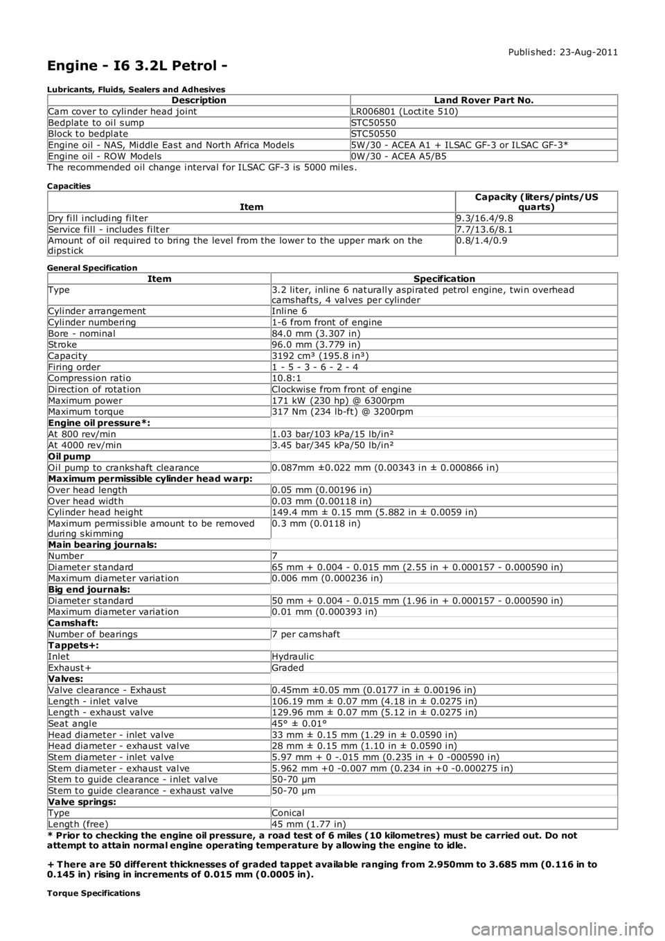
Publi s hed: 23-Aug-2011
Engine - I6 3.2L Petrol -
Lubricants, Fluids, Sealers and AdhesivesDescriptionLand Rover Part No.
Cam cover to cyli nder head jointLR006801 (Loct it e 510)
Bedplate to oi l s umpSTC50550Block t o bedpl ateSTC50550
Engine oil - NAS, Mi ddl e Eas t and Nort h Africa Models5W /30 - ACEA A1 + ILSAC GF-3 or ILSAC GF-3*
Engine oil - ROW Models0W /30 - ACEA A5/B5The recommended oil change i nterval for ILSAC GF-3 is 5000 mi les .
C apacities
ItemCapacity (liters/pints/USquarts)
Dry fi ll i ncludi ng fi lt er9.3/16.4/9.8
Service fil l - includes fi lt er7.7/13.6/8.1Amount of oil required t o bri ng the level from the lower to the upper mark on thedips t ick0.8/1.4/0.9
General Specification
ItemSpecificationType3.2 li ter, inli ne 6 nat urall y aspi rat ed pet rol engine, twi n overheadcams haft s, 4 val ves per cylinderCyli nder arrangementInli ne 6
Cyli nder numberi ng1-6 from front of engine
Bore - nominal84.0 mm (3.307 in)St roke96.0 mm (3.779 in)
Capaci ty3192 cm³ (195.8 i n³)
Firing order1 - 5 - 3 - 6 - 2 - 4Compres s ion rati o10.8:1
Di recti on of rotat ionCl ockwis e from front of engi ne
Maximum power171 kW (230 hp) @ 6300rpmMaximum t orque317 Nm (234 lb-ft ) @ 3200rpm
Engine oil pressure*:
At 800 rev/min1.03 bar/103 kPa/15 lb/in²At 4000 rev/min3.45 bar/345 kPa/50 lb/in²
Oil pump
Oi l pump to cranks haft clearance0.087mm ±0.022 mm (0.00343 i n ± 0.000866 i n)Maximum permissible cylinder head w arp:
Over head length0.05 mm (0.00196 i n)
Over head widt h0.03 mm (0.00118 i n)Cyli nder head height149.4 mm ± 0.15 mm (5.882 in ± 0.0059 i n)
Maximum permi s si ble amount t o be removedduri ng s ki mmi ng0.3 mm (0.0118 in)
Main bearing journals:
Number7
Di amet er s tandard65 mm + 0.004 - 0.015 mm (2.55 in + 0.000157 - 0.000590 in)Maximum diamet er variat ion0.006 mm (0.000236 in)
Big end journals:
Di amet er s tandard50 mm + 0.004 - 0.015 mm (1.96 in + 0.000157 - 0.000590 in)Maximum diamet er variat ion0.01 mm (0.000393 i n)
Camshaft:
Number of bearings7 per cams haftT appets+:
InletHydrauli c
Exhaus t +GradedValves:
Valve clearance - Exhaus t0.45mm ±0.05 mm (0.0177 in ± 0.00196 in)
Lengt h - i nlet valve106.19 mm ± 0.07 mm (4.18 in ± 0.0275 i n)Lengt h - exhaus t valve129.96 mm ± 0.07 mm (5.12 in ± 0.0275 i n)
Seat angl e45° ± 0.01°
Head diamet er - inlet valve33 mm ± 0.15 mm (1.29 in ± 0.0590 i n)Head diamet er - exhaus t val ve28 mm ± 0.15 mm (1.10 in ± 0.0590 i n)
St em diamet er - inlet valve5.97 mm + 0 -.015 mm (0.235 in + 0 -000590 i n)
St em diamet er - exhaus t val ve5.962 mm +0 -0.007 mm (0.234 in +0 -0.000275 i n)St em t o guide clearance - i nlet val ve50-70 µm
St em t o guide clearance - exhaus t valve50-70 µm
Valve springs:TypeConical
Lengt h (free)45 mm (1.77 in)
* Prior to checking the engine oil pressure, a road test of 6 miles (10 kilometres) must be carried out. Do notattempt to attain normal engine operating temperature by allowing the engine to idle.
+ T here are 50 different thicknesses of graded tappet available ranging from 2.950mm to 3.685 mm (0.116 in to0.145 in) rising in increments of 0.015 mm (0.0005 in).
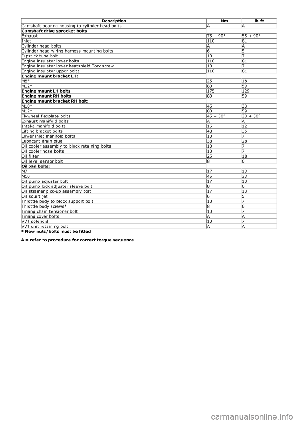
Torque Specifications
Page 604 of 3229

DescriptionNmlb-ft
Cams haft beari ng hous ing to cyli nder head bolt sAA
Camshaft drive sprocket boltsExhaus t75 + 90°55 + 90°
Inlet11081
Cyli nder head bolt sAACyli nder head wiring harnes s mount ing bolt s65
Di ps t ick t ube bol t107
Engine i ns ulat or lower bolt s11081Engine i ns ulat or lower heat s hield Torx s crew107
Engine i ns ulat or upper bolt s11081
Engine mount bracket LH:M8*2518
M12*8059
Engine mount LH bolts175129Engine mount RH bolts8059
Engine mount bracket RH bolt:
M10*4533M12*8059
Flywheel flexplat e bolt s45 + 50°33 + 50°
Exhaus t manifold bol tsAAIntake manifold bol ts1612
Lifti ng bracket bol ts4835
Lower inlet mani fold bol ts107Lubricant drain plug3828
Oi l cooler as sembl y t o block ret aining bol ts107
Oi l cooler hos e bolt s107Oi l fil ter2518
Oi l level s ensor bolt86
Oil pan bolts:M71713
M104533
Oi l pump adjus ter bolt1713Oi l pump lock adjus ter s leeve bolt86
Oi l st rai ner pi ck-up ass embly bol t1713
Oi l squirt jet65Throt tl e body to block support bolt107
Throt tl e body s crews*86
Timing chain t ensi oner bolt107Timing cover bolt sAA
VVT s olenoid107
VVT unit retai ni ng boltAA* New nuts/bolts must be fitted
A = refer to procedure for correct torque sequence
Page 630 of 3229

5-Bolt (2 of)6-Variable tract valveThe intake manifold att aches t o t he cylinder head wit h 6 bolt s and t he oil pan with 2 bolt s .
The manifold is capable of varying both int ake tract length and plenum volume by means of 2 separat e valves .
At low engine s peeds , long int ake tract s are ut iliz ed to provide opt imum engine t orque. Short er t racts are us ed at medium s peeds ,again, t o optimiz e engine t orque for t he exist ing engine s peed range.
At higher engine s peeds the benefit s of opt imizing t he t ract lengt hs are outweighed by the necess it y of maintaining anappropriate supply of air to meet t he engines requirement s . Therefore, t he plenum valve is opened t o create a s ingle, largeplenum volume to provide t he maximum quant ity of air t o charge the engines cylinders.For addit ional information, refer t o: Int ake Air Dis tribut ion and Filtering (303-12A Int ake Air Dis t ribution and Filt ering - I6 3.2LPet rol, Des cript ion and O perat ion).
Exhaust Manifold
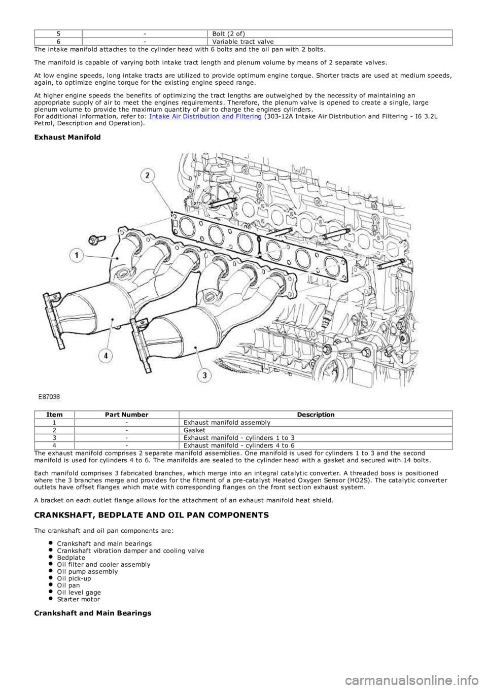
ItemPart NumberDescription1-Exhaus t manifold as sembly2-Gas ket3-Exhaus t manifold - cylinders 1 t o 34-Exhaus t manifold - cylinders 4 t o 6The exhaus t manifold compris es 2 s eparat e manifold as semblies . One manifold is us ed for cylinders 1 t o 3 and t he secondmanifold is us ed for cylinders 4 t o 6. The manifolds are sealed t o the cylinder head wit h a gas ket and s ecured with 14 bolts .
Each manifold comprises 3 fabricat ed branches , which merge int o an int egral cat alyt ic convert er. A t hreaded bos s is posit ionedwhere t he 3 branches merge and provides for t he fit ment of a pre-catalyst Heat ed O xygen Sens or (HO2S). The cat alyt ic convert erout let s have offset flanges which mat e wit h corresponding flanges on t he front s ect ion exhaust s ys t em.
A bracket on each out let flange allows for t he at t achment of an exhaus t manifold heat shield.
CRANKSHAFT, BEDPLATE AND OIL PAN COMPONENTS
The crankshaft and oil pan components are:
Cranks haft and main bearingsCranks haft vibrat ion damper and cooling valveBedplat eO il filter and cooler ass emblyO il pump ass emblyO il pick-upO il panO il level gageSt art er mot or
Crankshaft and Main Bearings
Page 638 of 3229
Oil Pan
ItemPart NumberDescription1-Oil pan2-Oil drain plugThe aluminium alloy s truct ural oil pan is bolted t o t he bedplat e.
• NOTE: The oil pan s hould always be fit ted proud of t he bedplat e by 0.05mm (+0mm -0.05mm).
A combined oil level/t emperat ure sensor is at t ached to t he underside of t he oil pan via 3 bolt s. The tip of the s ens or locat esthrough an aperture and is s ealed wit h an O-ring.
Page 639 of 3229
ItemPart NumberDescription1-Oil level/t emperat ure sensorThe engine oil drain plug is locat ed on t he exhaus t s ide of the engine, t owards t he bot t om of the oil pan.
Oil Level Gage
Page 640 of 3229
ItemPart NumberDescription1-Oil level gage2-Oil level gage t ube3-Bolt4-O-ring s ealThe oil level gauge locat es along t he int ake s ide of t he engine and is s upport ed in a t ube ins t alled in t he oil pan. A bolt s ecurelyat t aches the t ube to t he engine oil cooler via a bracket . Two holes in t he end of t he gauge indicate the minimum and maximum oillevels . The difference between the dips t ick markings , minimum and maximum, corresponds t o 0.8 lit res .
Starter Motor